1995 JEEP YJ fuel pump
[x] Cancel search: fuel pumpPage 1429 of 2158
DATA LINK CONNECTORÐPCM OUTPUT
Refer to the previous paragraphs on Data Link
ConnectorÐPCM Input for information.
EMR LAMPÐPCM OUTPUT
The EMR (SRI) lamp is not used for the 1995
model year.
FUEL PUMP RELAYÐPCM OUTPUT
The PCM energizes the fuel pump and the oxygen
sensor (O2S) heating element through the fuel pump
relay. Battery voltage is applied to the relay from the
ignition switch. The relay is energized when a
ground is provided by the PCM. Refer to Automatic
Shutdown Relay for additional information.
FUEL INJECTORSÐPCM OUTPUT
Six individual fuel injectors are used with the 4.0L
6-cylinder engine. Four individual fuel injectors are
used with the 2.5L 4-cylinder engine. The injectors
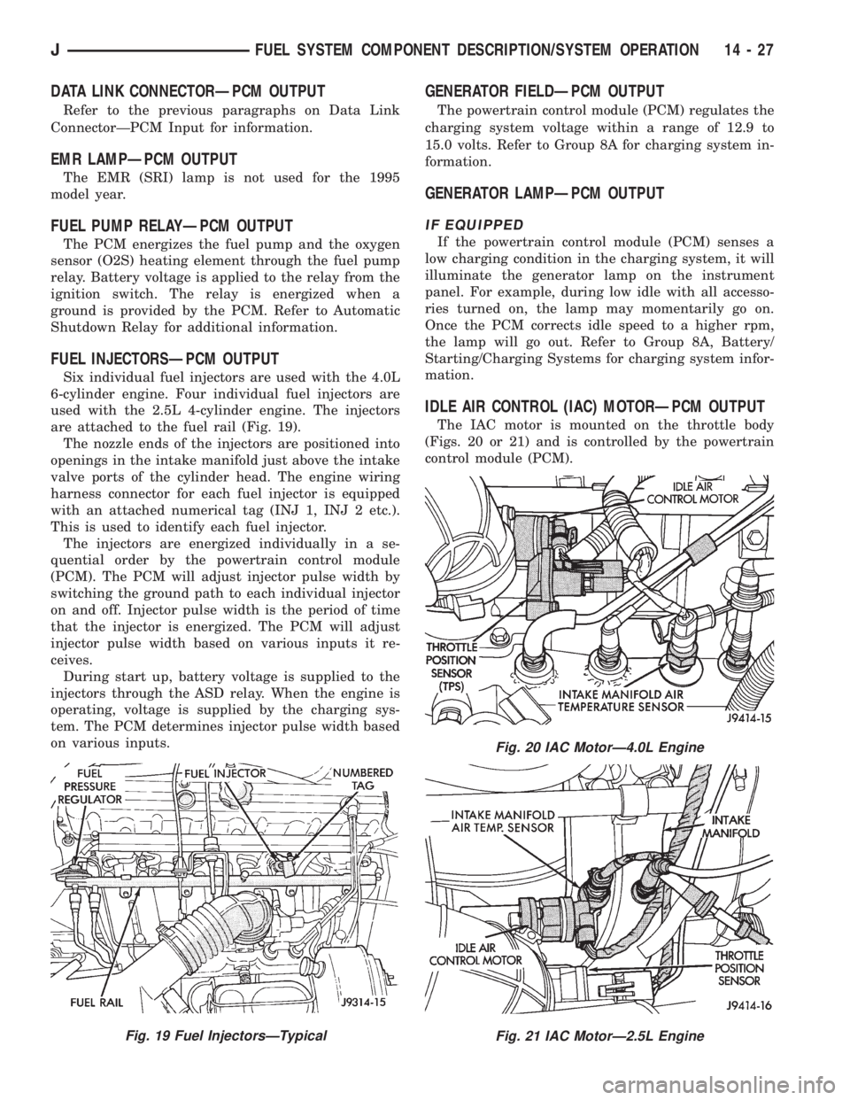
are attached to the fuel rail (Fig. 19).
The nozzle ends of the injectors are positioned into
openings in the intake manifold just above the intake
valve ports of the cylinder head. The engine wiring
harness connector for each fuel injector is equipped
with an attached numerical tag (INJ 1, INJ 2 etc.).
This is used to identify each fuel injector.
The injectors are energized individually in a se-
quential order by the powertrain control module
(PCM). The PCM will adjust injector pulse width by
switching the ground path to each individual injector
on and off. Injector pulse width is the period of time
that the injector is energized. The PCM will adjust
injector pulse width based on various inputs it re-
ceives.
During start up, battery voltage is supplied to the
injectors through the ASD relay. When the engine is
operating, voltage is supplied by the charging sys-
tem. The PCM determines injector pulse width based
on various inputs.
GENERATOR FIELDÐPCM OUTPUT
The powertrain control module (PCM) regulates the
charging system voltage within a range of 12.9 to
15.0 volts. Refer to Group 8A for charging system in-
formation.
GENERATOR LAMPÐPCM OUTPUT
IF EQUIPPED
If the powertrain control module (PCM) senses a
low charging condition in the charging system, it will
illuminate the generator lamp on the instrument
panel. For example, during low idle with all accesso-
ries turned on, the lamp may momentarily go on.
Once the PCM corrects idle speed to a higher rpm,
the lamp will go out. Refer to Group 8A, Battery/
Starting/Charging Systems for charging system infor-
mation.
IDLE AIR CONTROL (IAC) MOTORÐPCM OUTPUT
The IAC motor is mounted on the throttle body
(Figs. 20 or 21) and is controlled by the powertrain
control module (PCM).
Fig. 19 Fuel InjectorsÐTypical
Fig. 20 IAC MotorÐ4.0L Engine
Fig. 21 IAC MotorÐ2.5L Engine
JFUEL SYSTEM COMPONENT DESCRIPTION/SYSTEM OPERATION 14 - 27
Page 1433 of 2158
²The powertrain control module (PCM) pre-posi-
tions the idle air control (IAC) motor.
²The PCM determines atmospheric air pressure
from the MAP sensor input to determine basic fuel
strategy.
²The PCM monitors the engine coolant temperature
sensor input. The PCM modifies fuel strategy based
on this input.
²Intake manifold air temperature sensor input is
monitored
²Throttle position sensor (TPS) is monitored
²The auto shutdown (ASD) relay is energized by the
PCM for approximately three seconds.
²The fuel pump is energized through the fuel pump
relay by the PCM. The fuel pump will operate for ap-
proximately three seconds unless the engine is oper-
ating or the starter motor is engaged
²The O2S sensor heater element is energized
through the fuel pump relay. The O2S sensor input is
not used by the PCM to calibrate air-fuel ratio dur-
ing this mode of operation.
²The up-shift indicator lamp is illuminated (manual
transmission only).
ENGINE START-UP MODE
This is an Open Loop mode. The following actions
occur when the starter motor is engaged.
The powertrain control module (PCM) receives in-
puts from:
²Battery voltage
²Engine coolant temperature sensor
²Crankshaft position sensor
²Intake manifold air temperature sensor
²Manifold absolute pressure (MAP) sensor
²Throttle position sensor (TPS)
²Starter motor relay
²Camshaft position sensor signal
The PCM monitors the crankshaft position sensor.
If the PCM does not receive a crankshaft position
sensor signal within 3 seconds of cranking the en-
gine, it will shut down the fuel injection system.
The fuel pump is activated by the PCM through
the fuel pump relay.
Voltage is applied to the fuel injectors with the
PCM. The PCM will then control the injection se-
quence and injector pulse width by turning the
ground circuit to each individual injector on and off.
The PCM determines the proper ignition timing ac-
cording to input received from the crankshaft posi-
tion sensor.
ENGINE WARM-UP MODE
This is an Open Loop mode. During engine warm-
up, the powertrain control module (PCM) receives in-
puts from:
²Battery voltage
²Crankshaft position sensor
²Engine coolant temperature sensor²Intake manifold air temperature sensor
²Manifold absolute pressure (MAP) sensor
²Throttle position sensor (TPS)
²Camshaft position sensor signal (in the distribu-
tor)
²Park/neutral switch (gear indicator signalÐauto.
trans. only)
²Air conditioning select signal (if equipped)
²Air conditioning request signal (if equipped)
Based on these inputs the following occurs:
²Voltage is applied to the fuel injectors with the
powertrain control module (PCM). The PCM will
then control the injection sequence and injector pulse
width by turning the ground circuit to each individ-
ual injector on and off.
²The PCM adjusts engine idle speed through the
idle air control (IAC) motor and adjusts ignition tim-
ing.
²The PCM operates the A/C compressor clutch
through the clutch relay. This is done if A/C has been
selected by the vehicle operator and requested by the
A/C thermostat.
²If the vehicle has a manual transmission, the up-
shift lamp is operated by the PCM.
²When engine has reached operating temperature,
the PCM will begin monitoring O2S sensor input.
The system will then leave the warm-up mode and go
into closed loop operation.
IDLE MODE
When the engine is at operating temperature, this
is a Closed Loop mode. At idle speed, the powertrain
control module (PCM) receives inputs from:
²Air conditioning select signal (if equipped)
²Air conditioning request signal (if equipped)
²Battery voltage
²Crankshaft position sensor
²Engine coolant temperature sensor
²Intake manifold air temperature sensor
²Manifold absolute pressure (MAP) sensor
²Throttle position sensor (TPS)
²Camshaft position sensor signal (in the distribu-
tor)
²Battery voltage
²Park/neutral switch (gear indicator signalÐauto.
trans. only)
²Oxygen sensor
Based on these inputs, the following occurs:
²Voltage is applied to the fuel injectors with the
powertrain control module (PCM). The PCM will
then control injection sequence and injector pulse
width by turning the ground circuit to each individ-
ual injector on and off.
²The PCM monitors the O2S sensor input and ad-
justs air-fuel ratio by varying injector pulse width. It
also adjusts engine idle speed through the idle air
control (IAC) motor.
JFUEL SYSTEM COMPONENT DESCRIPTION/SYSTEM OPERATION 14 - 31
Page 1435 of 2158
²The PCM opens the ground circuit to the A/C
clutch relay to disengage the A/C compressor clutch.
This will be done for approximately 15 seconds (if the
air conditioning system is operating).
If the vehicle has a manual transmission, the up-
shift lamp is operated by the PCM.
IGNITION SWITCH OFF MODE
When ignition switch is turned to OFF position,
the PCM stops operating the injectors, ignition coil,
ASD relay and fuel pump relay.
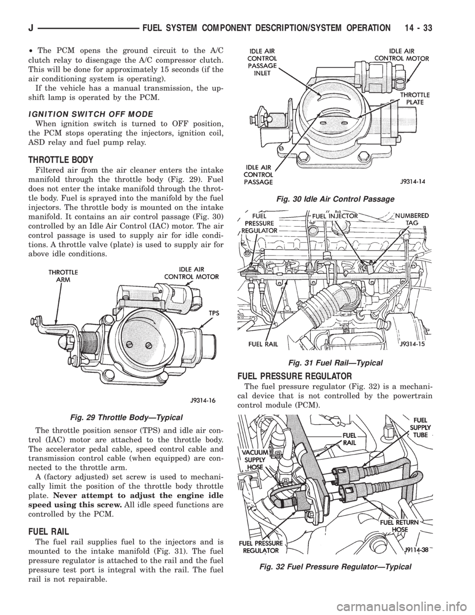
THROTTLE BODY
Filtered air from the air cleaner enters the intake
manifold through the throttle body (Fig. 29). Fuel
does not enter the intake manifold through the throt-
tle body. Fuel is sprayed into the manifold by the fuel
injectors. The throttle body is mounted on the intake
manifold. It contains an air control passage (Fig. 30)
controlled by an Idle Air Control (IAC) motor. The air
control passage is used to supply air for idle condi-
tions. A throttle valve (plate) is used to supply air for
above idle conditions.
The throttle position sensor (TPS) and idle air con-
trol (IAC) motor are attached to the throttle body.
The accelerator pedal cable, speed control cable and
transmission control cable (when equipped) are con-
nected to the throttle arm.
A (factory adjusted) set screw is used to mechani-
cally limit the position of the throttle body throttle
plate.Never attempt to adjust the engine idle
speed using this screw.All idle speed functions are
controlled by the PCM.
FUEL RAIL
The fuel rail supplies fuel to the injectors and is
mounted to the intake manifold (Fig. 31). The fuel
pressure regulator is attached to the rail and the fuel
pressure test port is integral with the rail. The fuel
rail is not repairable.
FUEL PRESSURE REGULATOR
The fuel pressure regulator (Fig. 32) is a mechani-
cal device that is not controlled by the powertrain
control module (PCM).
Fig. 29 Throttle BodyÐTypical
Fig. 30 Idle Air Control Passage
Fig. 31 Fuel RailÐTypical
Fig. 32 Fuel Pressure RegulatorÐTypical
JFUEL SYSTEM COMPONENT DESCRIPTION/SYSTEM OPERATION 14 - 33
Page 1437 of 2158
MULTI-PORT FUEL INJECTION (MFI)ÐGENERAL DIAGNOSIS
INDEX
page page
Automatic Shutdown (ASD) Relay Testing....... 46
Camshaft Position Sensor Test............... 46
Crankshaft Position Sensor Test.............. 47
Diagnostic Trouble Code (DTC)............... 54
DRB Scan Tool........................... 54
Engine Coolant Temperature Sensor Test....... 46
Extended Idle Switch Test................... 48
Fuel Injector Test......................... 51
Fuel Pump Relay Testing................... 47
Fuel System Pressure Test.................. 51
General Information....................... 35
Idle Air Control Motor Test................... 49
Intake Manifold Air Temperature Sensor Test..... 46Manifold Absolute Pressure (Map) Sensor Test . . . 47
On-Board Diagnostics (OBD)................. 51
Oxygen Sensor (O2S) Heating Element Test..... 48
Pcm System Schematics.................... 41
Powertrain Control Module (PCM) 60-Way
Connector............................. 40
RelaysÐOperation/Testing.................. 50
Starter Motor Relay Test.................... 51
Throttle Position Sensor (TPS) Test............ 48
Torque Converter Clutch Relay Test............ 48
Vehicle Speed Sensor Test.................. 48
Visual Inspection.......................... 35
GENERAL INFORMATION
All 2.5L 4-cylinder and 4.0L 6-cylinder engines are
equipped with sequential Multi-Port Fuel Injection
(MFI). The MFI system provides precise air/fuel ra-
tios for all driving conditions.
VISUAL INSPECTION
A visual inspection for loose, disconnected, or incor-
rectly routed wires and hoses should be made. This
should be done before attempting to diagnose or ser-
vice the fuel injection system. A visual check will
help spot these faults and save unnecessary test and
diagnostic time. A thorough visual inspection will in-
clude the following checks:
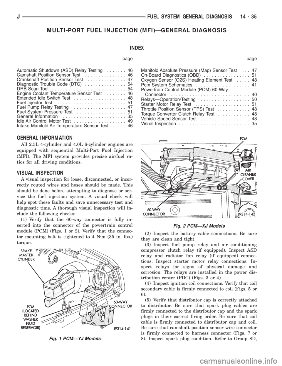
(1) Verify that the 60-way connector is fully in-
serted into the connector of the powertrain control
module (PCM) (Figs. 1 or 2). Verify that the connec-
tor mounting bolt is tightened to 4 Nzm (35 in. lbs.)
torque.(2) Inspect the battery cable connections. Be sure
they are clean and tight.
(3) Inspect fuel pump relay and air conditioning
compressor clutch relay (if equipped). Inspect ASD
relay and radiator fan relay (if equipped) connec-
tions. Inspect starter motor relay connections. In-
spect relays for signs of physical damage and
corrosion. The relays are installed in the power dis-
tribution center (PDC) (Figs. 3 or 4).
(4) Inspect ignition coil connections. Verify that coil
secondary cable is firmly connected to coil (Figs. 5 or
6).
(5) Verify that distributor cap is correctly attached
to distributor. Be sure that spark plug cables are
firmly connected to the distributor cap and the spark
plugs in their correct firing order. Be sure that coil
cable is firmly connected to distributor cap and coil.
Be sure that camshaft position sensor wire connector
is firmly connected to harness connector (Figs. 7 or
8). Inspect spark plug condition. Refer to Group 8D,
Fig. 1 PCMÐYJ Models
Fig. 2 PCMÐXJ Models
JFUEL SYSTEM GENERAL DIAGNOSIS 14 - 35
Page 1442 of 2158
plugged catalytic convertor.
(27) If equipped with automatic transmission, ver-
ify that electrical harness is firmly connected to park/
neutral safety switch. Refer to Automatic
Transmission section of Group 21.
(28) Verify that the harness connector is firmly
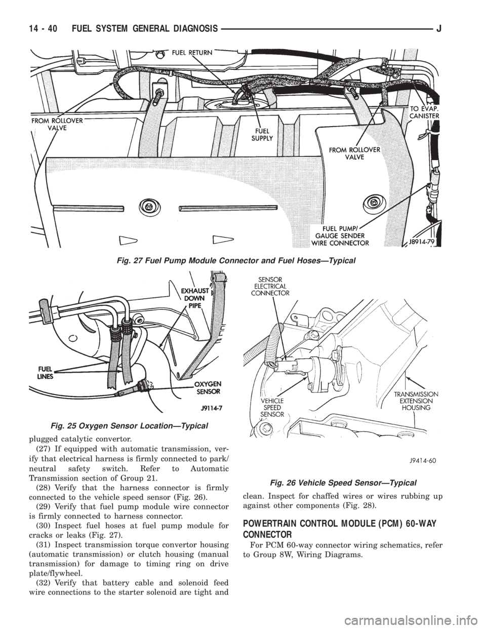
connected to the vehicle speed sensor (Fig. 26).
(29) Verify that fuel pump module wire connector
is firmly connected to harness connector.
(30) Inspect fuel hoses at fuel pump module for
cracks or leaks (Fig. 27).
(31) Inspect transmission torque convertor housing
(automatic transmission) or clutch housing (manual
transmission) for damage to timing ring on drive
plate/flywheel.
(32) Verify that battery cable and solenoid feed
wire connections to the starter solenoid are tight andclean. Inspect for chaffed wires or wires rubbing up
against other components (Fig. 28).
POWERTRAIN CONTROL MODULE (PCM) 60-WAY
CONNECTOR
For PCM 60-way connector wiring schematics, refer
to Group 8W, Wiring Diagrams.
Fig. 27 Fuel Pump Module Connector and Fuel HosesÐTypical
Fig. 25 Oxygen Sensor LocationÐTypical
Fig. 26 Vehicle Speed SensorÐTypical
14 - 40 FUEL SYSTEM GENERAL DIAGNOSISJ
Page 1449 of 2158
Test the resistance of the wire harness. Do this be-
tween the powertrain control module (PCM) wire
harness connector terminal-2 and the sensor connec-
tor terminal. Also test terminal-4 to the sensor con-
nector terminal. Repair the wire harness as
necessary if the resistance is greater than 1 ohm.
FUEL PUMP RELAY TESTING
For testing this relay, refer to RelaysÐOperation/
Testing in this section of the group.
MANIFOLD ABSOLUTE PRESSURE (MAP) SENSOR
TEST
To perform a complete test of the MAP sensor and
its circuitry, refer to DRB scan tool and appropriate
Powertrain Diagnostics Procedures manual. To test
the sensor only, refer to the following:
Inspect the MAP sensor vacuum hose connections
at the throttle body and sensor. Repair as necessary.
CAUTION: When testing, do not remove the electri-
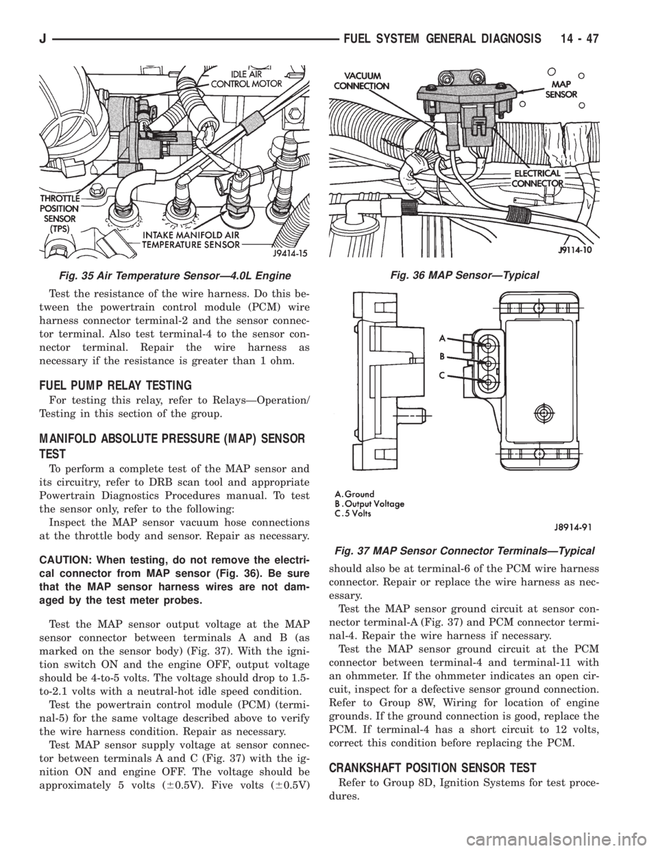
cal connector from MAP sensor (Fig. 36). Be sure
that the MAP sensor harness wires are not dam-
aged by the test meter probes.
Test the MAP sensor output voltage at the MAP
sensor connector between terminals A and B (as
marked on the sensor body) (Fig. 37). With the igni-
tion switch ON and the engine OFF, output voltage
should be 4-to-5 volts. The voltage should drop to 1.5-
to-2.1 volts with a neutral-hot idle speed condition.
Test the powertrain control module (PCM) (termi-
nal-5) for the same voltage described above to verify
the wire harness condition. Repair as necessary.
Test MAP sensor supply voltage at sensor connec-
tor between terminals A and C (Fig. 37) with the ig-
nition ON and engine OFF. The voltage should be
approximately 5 volts (60.5V). Five volts (60.5V)should also be at terminal-6 of the PCM wire harness
connector. Repair or replace the wire harness as nec-
essary.
Test the MAP sensor ground circuit at sensor con-
nector terminal-A (Fig. 37) and PCM connector termi-
nal-4. Repair the wire harness if necessary.
Test the MAP sensor ground circuit at the PCM
connector between terminal-4 and terminal-11 with
an ohmmeter. If the ohmmeter indicates an open cir-
cuit, inspect for a defective sensor ground connection.
Refer to Group 8W, Wiring for location of engine
grounds. If the ground connection is good, replace the
PCM. If terminal-4 has a short circuit to 12 volts,
correct this condition before replacing the PCM.
CRANKSHAFT POSITION SENSOR TEST
Refer to Group 8D, Ignition Systems for test proce-
dures.
Fig. 35 Air Temperature SensorÐ4.0L EngineFig. 36 MAP SensorÐTypical
Fig. 37 MAP Sensor Connector TerminalsÐTypical
JFUEL SYSTEM GENERAL DIAGNOSIS 14 - 47
Page 1452 of 2158
RELAYSÐOPERATION/TESTING
OPERATION
The following operations/tests apply to these
relays only:automatic shutdown (ASD), fuel pump
and torque converter clutch. For operations/tests on
all other relays, refer to the appropriate section of
this service manual.
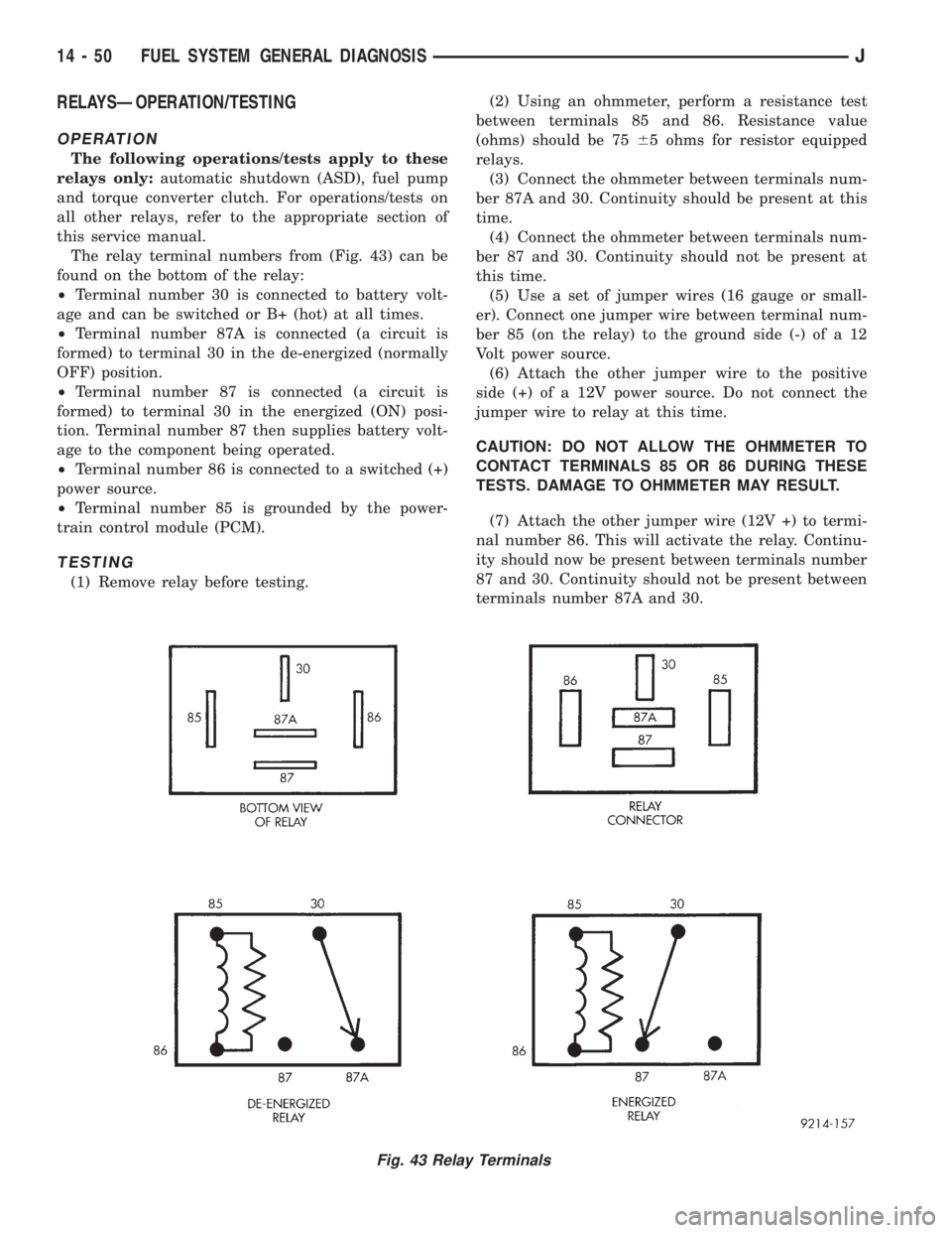
The relay terminal numbers from (Fig. 43) can be
found on the bottom of the relay:
²Terminal number 30 is connected to battery volt-
age and can be switched or B+ (hot) at all times.
²Terminal number 87A is connected (a circuit is
formed) to terminal 30 in the de-energized (normally
OFF) position.
²Terminal number 87 is connected (a circuit is
formed) to terminal 30 in the energized (ON) posi-
tion. Terminal number 87 then supplies battery volt-
age to the component being operated.
²Terminal number 86 is connected to a switched (+)
power source.
²Terminal number 85 is grounded by the power-
train control module (PCM).
TESTING
(1) Remove relay before testing.(2) Using an ohmmeter, perform a resistance test
between terminals 85 and 86. Resistance value
(ohms) should be 7565 ohms for resistor equipped
relays.
(3) Connect the ohmmeter between terminals num-
ber 87A and 30. Continuity should be present at this
time.
(4) Connect the ohmmeter between terminals num-
ber 87 and 30. Continuity should not be present at
this time.
(5) Use a set of jumper wires (16 gauge or small-
er). Connect one jumper wire between terminal num-
ber 85 (on the relay) to the ground side (-) of a 12
Volt power source.
(6) Attach the other jumper wire to the positive
side (+) of a 12V power source. Do not connect the
jumper wire to relay at this time.
CAUTION: DO NOT ALLOW THE OHMMETER TO
CONTACT TERMINALS 85 OR 86 DURING THESE
TESTS. DAMAGE TO OHMMETER MAY RESULT.
(7) Attach the other jumper wire (12V +) to termi-
nal number 86. This will activate the relay. Continu-
ity should now be present between terminals number
87 and 30. Continuity should not be present between
terminals number 87A and 30.
Fig. 43 Relay Terminals
14 - 50 FUEL SYSTEM GENERAL DIAGNOSISJ
Page 1453 of 2158
(8) Disconnect jumper wires from relay and 12 Volt
power source.
If continuity or resistance tests did not pass, re-
place relay. If tests passed, refer to Group 8W, Wiring
Diagrams for additional circuit information. Also re-
fer to the appropriate Powertrain Diagnostic Proce-
dures manual for operation of the DRB scan tool.
STARTER MOTOR RELAY TEST
Refer to Group 8A, Battery/Starting/Charging/Sys-
tem Diagnostics, for starter motor relay testing.
FUEL INJECTOR TEST
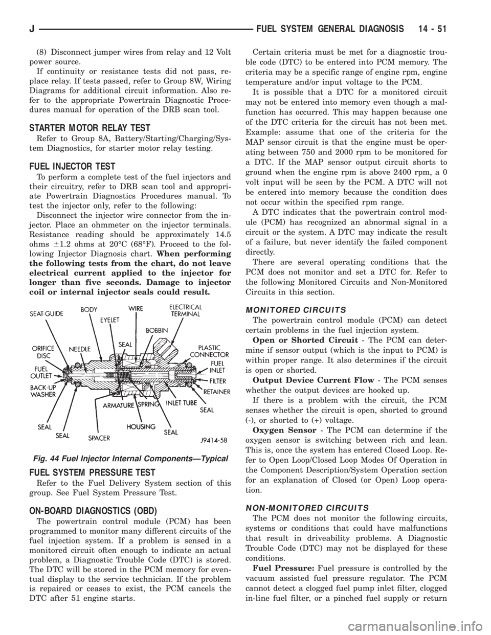
To perform a complete test of the fuel injectors and
their circuitry, refer to DRB scan tool and appropri-
ate Powertrain Diagnostics Procedures manual. To
test the injector only, refer to the following:
Disconnect the injector wire connector from the in-
jector. Place an ohmmeter on the injector terminals.
Resistance reading should be approximately 14.5
ohms61.2 ohms at 20ÉC (68ÉF). Proceed to the fol-
lowing Injector Diagnosis chart.When performing
the following tests from the chart, do not leave
electrical current applied to the injector for
longer than five seconds. Damage to injector
coil or internal injector seals could result.
FUEL SYSTEM PRESSURE TEST
Refer to the Fuel Delivery System section of this
group. See Fuel System Pressure Test.
ON-BOARD DIAGNOSTICS (OBD)
The powertrain control module (PCM) has been
programmed to monitor many different circuits of the
fuel injection system. If a problem is sensed in a
monitored circuit often enough to indicate an actual
problem, a Diagnostic Trouble Code (DTC) is stored.
The DTC will be stored in the PCM memory for even-
tual display to the service technician. If the problem
is repaired or ceases to exist, the PCM cancels the
DTC after 51 engine starts.Certain criteria must be met for a diagnostic trou-
ble code (DTC) to be entered into PCM memory. The
criteria may be a specific range of engine rpm, engine
temperature and/or input voltage to the PCM.
It is possible that a DTC for a monitored circuit
may not be entered into memory even though a mal-
function has occurred. This may happen because one
of the DTC criteria for the circuit has not been met.
Example: assume that one of the criteria for the
MAP sensor circuit is that the engine must be oper-
ating between 750 and 2000 rpm to be monitored for
a DTC. If the MAP sensor output circuit shorts to
ground when the engine rpm is above 2400 rpm, a 0
volt input will be seen by the PCM. A DTC will not
be entered into memory because the condition does
not occur within the specified rpm range.
A DTC indicates that the powertrain control mod-
ule (PCM) has recognized an abnormal signal in a
circuit or the system. A DTC may indicate the result
of a failure, but never identify the failed component
directly.
There are several operating conditions that the
PCM does not monitor and set a DTC for. Refer to
the following Monitored Circuits and Non-Monitored
Circuits in this section.
MONITORED CIRCUITS
The powertrain control module (PCM) can detect
certain problems in the fuel injection system.
Open or Shorted Circuit- The PCM can deter-
mine if sensor output (which is the input to PCM) is
within proper range. It also determines if the circuit
is open or shorted.
Output Device Current Flow- The PCM senses
whether the output devices are hooked up.
If there is a problem with the circuit, the PCM
senses whether the circuit is open, shorted to ground
(-), or shorted to (+) voltage.
Oxygen Sensor- The PCM can determine if the
oxygen sensor is switching between rich and lean.
This is, once the system has entered Closed Loop. Re-
fer to Open Loop/Closed Loop Modes Of Operation in
the Component Description/System Operation section
for an explanation of Closed (or Open) Loop opera-
tion.
NON-MONITORED CIRCUITS
The PCM does not monitor the following circuits,
systems or conditions that could have malfunctions
that result in driveability problems. A Diagnostic
Trouble Code (DTC) may not be displayed for these
conditions.
Fuel Pressure:Fuel pressure is controlled by the
vacuum assisted fuel pressure regulator. The PCM
cannot detect a clogged fuel pump inlet filter, clogged
in-line fuel filter, or a pinched fuel supply or return
Fig. 44 Fuel Injector Internal ComponentsÐTypical
JFUEL SYSTEM GENERAL DIAGNOSIS 14 - 51