Page 1971 of 2158
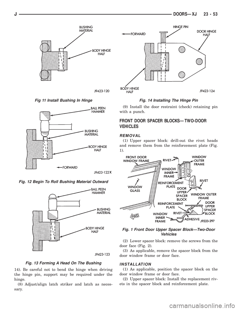
14). Be careful not to bend the hinge when driving
the hinge pin, support may be required under the
hinge.
(8) Adjust/align latch striker and latch as neces-
sary.(9) Install the door restraint (check) retaining pin
with a punch.
FRONT DOOR SPACER BLOCKSÐTWO-DOOR
VEHICLES
REMOVAL
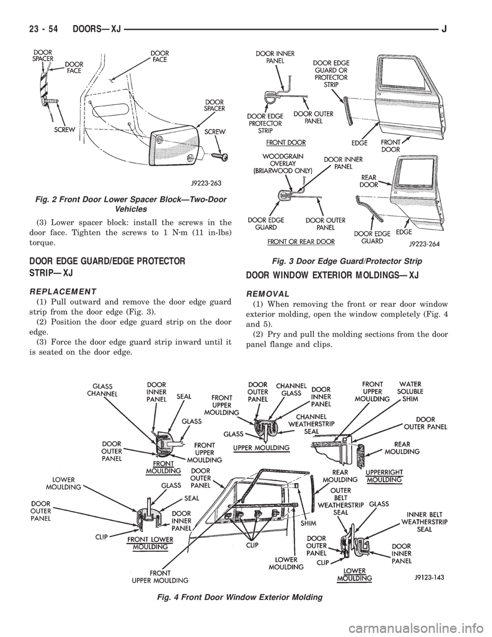
(1) Upper spacer block: drill-out the rivet heads
and remove them from the reinforcement plate (Fig.
1).
(2) Lower spacer block: remove the screws from the
door face (Fig. 2).
(3) As applicable, remove the spacer block from the
door window frame or door face.
INSTALLATION
(1) As applicable, position the spacer block on the
door window frame or door face.
(2) Upper spacer block: Install the replacement riv-
ets in the spacer block and reinforcement plate.
Fig 11 Install Bushing In Hinge
Fig. 12 Begin To Roll Bushing Material Outward
Fig. 13 Forming A Head On The Bushing
Fig. 14 Installing The Hinge Pin
Fig. 1 Front Door Upper Spacer BlockÐTwo-Door
Vehicles
JDOORSÐXJ 23 - 53
Page 1972 of 2158
(3) Lower spacer block: install the screws in the
door face. Tighten the screws to 1 Nzm (11 in-lbs)
torque.
DOOR EDGE GUARD/EDGE PROTECTOR
STRIPÐXJ
REPLACEMENT
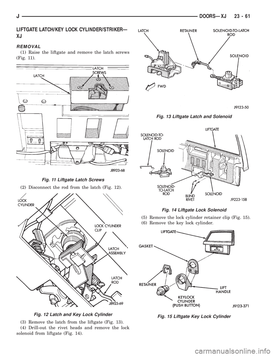
(1) Pull outward and remove the door edge guard
strip from the door edge (Fig. 3).
(2) Position the door edge guard strip on the door
edge.
(3) Force the door edge guard strip inward until it
is seated on the door edge.
DOOR WINDOW EXTERIOR MOLDINGSÐXJ
REMOVAL
(1) When removing the front or rear door window
exterior molding, open the window completely (Fig. 4
and 5).
(2) Pry and pull the molding sections from the door
panel flange and clips.
Fig. 3 Door Edge Guard/Protector Strip
Fig. 4 Front Door Window Exterior Molding
Fig. 2 Front Door Lower Spacer BlockÐTwo-Door
Vehicles
23 - 54 DOORSÐXJJ
Page 1979 of 2158
LIFTGATE LATCH/KEY LOCK CYLINDER/STRIKERÐ
XJ
REMOVAL
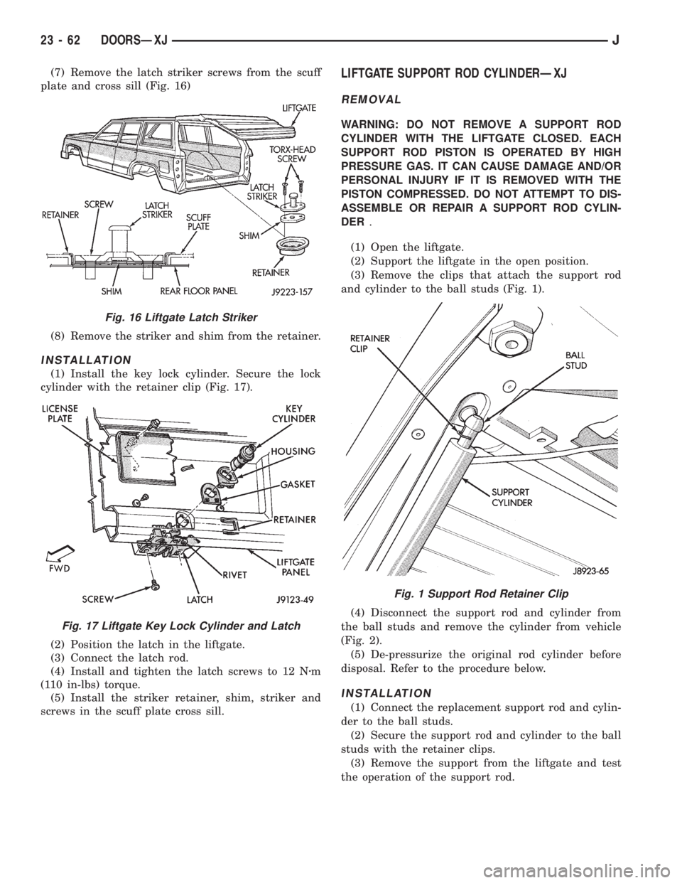
(1) Raise the liftgate and remove the latch screws
(Fig. 11).
(2) Disconnect the rod from the latch (Fig. 12).
(3) Remove the latch from the liftgate (Fig. 13).
(4) Drill-out the rivet heads and remove the lock
solenoid from liftgate (Fig. 14).(5) Remove the lock cylinder retainer clip (Fig. 15).
(6) Remove the key lock cylinder.
Fig. 11 Liftgate Latch Screws
Fig. 12 Latch and Key Lock Cylinder
Fig. 13 Liftgate Latch and Solenoid
Fig. 14 Liftgate Lock Solenoid
Fig. 15 Liftgate Key Lock Cylinder
JDOORSÐXJ 23 - 61
Page 1980 of 2158
(7) Remove the latch striker screws from the scuff
plate and cross sill (Fig. 16)
(8) Remove the striker and shim from the retainer.
INSTALLATION
(1) Install the key lock cylinder. Secure the lock
cylinder with the retainer clip (Fig. 17).
(2) Position the latch in the liftgate.
(3) Connect the latch rod.
(4) Install and tighten the latch screws to 12 Nzm
(110 in-lbs) torque.
(5) Install the striker retainer, shim, striker and
screws in the scuff plate cross sill.
LIFTGATE SUPPORT ROD CYLINDERÐXJ
REMOVAL
WARNING: DO NOT REMOVE A SUPPORT ROD
CYLINDER WITH THE LIFTGATE CLOSED. EACH
SUPPORT ROD PISTON IS OPERATED BY HIGH
PRESSURE GAS. IT CAN CAUSE DAMAGE AND/OR
PERSONAL INJURY IF IT IS REMOVED WITH THE
PISTON COMPRESSED. DO NOT ATTEMPT TO DIS-
ASSEMBLE OR REPAIR A SUPPORT ROD CYLIN-
DER.
(1) Open the liftgate.
(2) Support the liftgate in the open position.
(3) Remove the clips that attach the support rod
and cylinder to the ball studs (Fig. 1).
(4) Disconnect the support rod and cylinder from
the ball studs and remove the cylinder from vehicle
(Fig. 2).
(5) De-pressurize the original rod cylinder before
disposal. Refer to the procedure below.
INSTALLATION
(1) Connect the replacement support rod and cylin-
der to the ball studs.
(2) Secure the support rod and cylinder to the ball
studs with the retainer clips.
(3) Remove the support from the liftgate and test
the operation of the support rod.
Fig. 16 Liftgate Latch Striker
Fig. 17 Liftgate Key Lock Cylinder and Latch
Fig. 1 Support Rod Retainer Clip
23 - 62 DOORSÐXJJ
Page 1982 of 2158
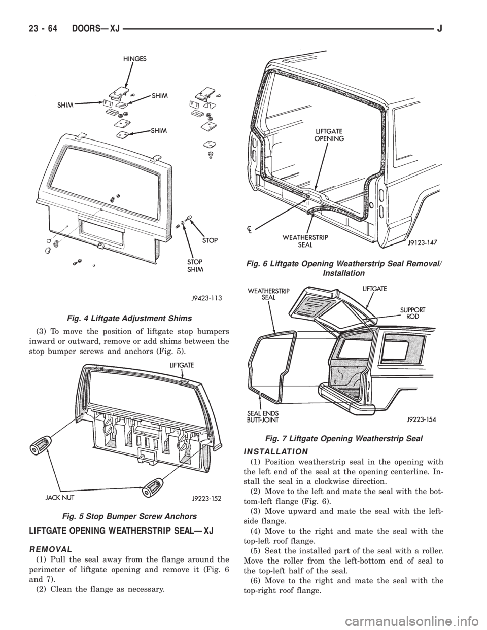
(3) To move the position of liftgate stop bumpers
inward or outward, remove or add shims between the
stop bumper screws and anchors (Fig. 5).
LIFTGATE OPENING WEATHERSTRIP SEALÐXJ
REMOVAL
(1) Pull the seal away from the flange around the
perimeter of liftgate opening and remove it (Fig. 6
and 7).
(2) Clean the flange as necessary.
INSTALLATION
(1) Position weatherstrip seal in the opening with
the left end of the seal at the opening centerline. In-
stall the seal in a clockwise direction.
(2) Move to the left and mate the seal with the bot-
tom-left flange (Fig. 6).
(3) Move upward and mate the seal with the left-
side flange.
(4) Move to the right and mate the seal with the
top-left roof flange.
(5) Seat the installed part of the seal with a roller.
Move the roller from the left-bottom end of seal to
the top-left half of the seal.
(6) Move to the right and mate the seal with the
top-right roof flange.
Fig. 4 Liftgate Adjustment Shims
Fig. 5 Stop Bumper Screw Anchors
Fig. 6 Liftgate Opening Weatherstrip Seal Removal/
Installation
Fig. 7 Liftgate Opening Weatherstrip Seal
23 - 64 DOORSÐXJJ
Page 2022 of 2158
EXTERIOR COMPONENTS
INDEX
page page
Battery TrayÐYJ......................... 110
Body Side Step MoldingÐYJ................ 115
Body Stripes/DecalsÐYJ................... 116
Cowl Grille and ScreenÐYJ................ 109
Cowl Weatherstrip SealÐYJ................ 109
Exterior Nameplates (Adhesive-Backed)ÐYJ.... 120
External Spare/Wheel Tire CarrierÐYJ........ 133
Fender FlareÐYJ........................ 114
Fender Inner Splash ShieldsÐYJ............. 116
Fender Splash ApronsÐYJ................. 115
FendersÐYJ............................ 110
Fuel Filler Protector/NozzleÐYJ............. 121
Half Metal Door Mirror (External)ÐYJ......... 121
Hard Top Liftgate GlassÐYJ................ 124
Hard Top RepairÐYJ..................... 127
Hard Top Roof VentÐYJ................... 127
Hard TopÐYJ........................... 126Hood AlignmentÐYJ...................... 107
Hood Insulator PanelÐYJ.................. 107
Hood Safety LatchÐYJ.................... 109
HoodÐYJ.............................. 107
Liftgate Glass Weatherstrip Seal ReplacementÐYJ. 125
Radiator Grille AppliqueÐYJ................ 104
Soft Top Service InformationÐYJ............. 127
Soft Top ServiceÐYJ..................... 129
Sport BarÐYJ........................... 132
Tailgate AdjustmentÐYJ................... 121
Tailgate HingeÐYJ....................... 121
Tailgate Latch and Release HandleÐYJ........ 122
Tailgate Latch StrikerÐYJ.................. 123
Tailgate Lock CylinderÐYJ................. 122
Tailgate Weatherstrip SealÐYJ.............. 123
TailgateÐYJ............................ 121
Wheelhouse Splash LinersÐYJ.............. 115
RADIATOR GRILLE APPLIQUEÐYJ
REMOVAL
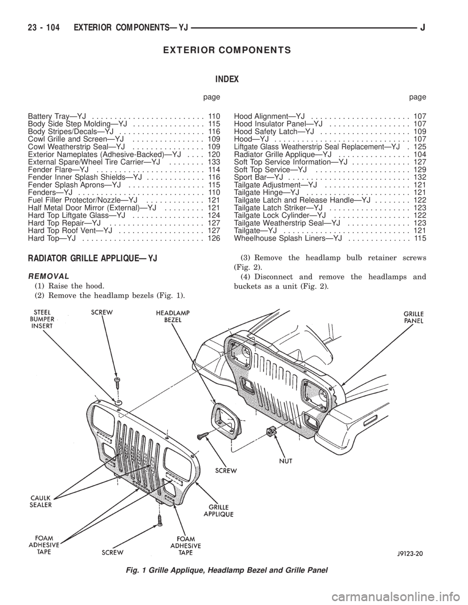
(1) Raise the hood.
(2) Remove the headlamp bezels (Fig. 1).(3) Remove the headlamp bulb retainer screws
(Fig. 2).
(4) Disconnect and remove the headlamps and
buckets as a unit (Fig. 2).
Fig. 1 Grille Applique, Headlamp Bezel and Grille Panel
23 - 104 EXTERIOR COMPONENTSÐYJJ
Page 2047 of 2158
SOFT TOP SERVICEÐYJ
REMOVAL
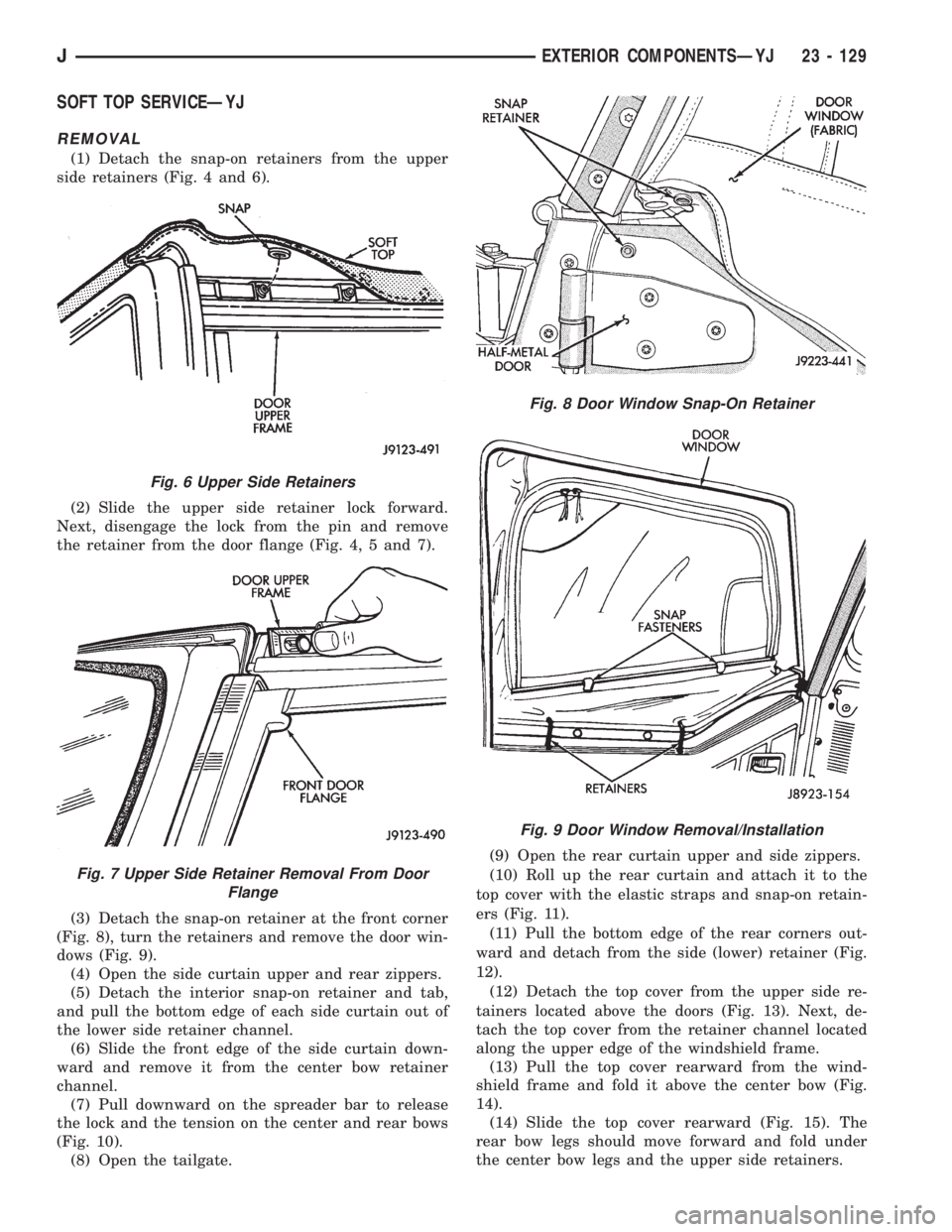
(1) Detach the snap-on retainers from the upper
side retainers (Fig. 4 and 6).
(2) Slide the upper side retainer lock forward.
Next, disengage the lock from the pin and remove
the retainer from the door flange (Fig. 4, 5 and 7).
(3) Detach the snap-on retainer at the front corner
(Fig. 8), turn the retainers and remove the door win-
dows (Fig. 9).
(4) Open the side curtain upper and rear zippers.
(5) Detach the interior snap-on retainer and tab,
and pull the bottom edge of each side curtain out of
the lower side retainer channel.
(6) Slide the front edge of the side curtain down-
ward and remove it from the center bow retainer
channel.
(7) Pull downward on the spreader bar to release
the lock and the tension on the center and rear bows
(Fig. 10).
(8) Open the tailgate.(9) Open the rear curtain upper and side zippers.
(10) Roll up the rear curtain and attach it to the
top cover with the elastic straps and snap-on retain-
ers (Fig. 11).
(11) Pull the bottom edge of the rear corners out-
ward and detach from the side (lower) retainer (Fig.
12).
(12) Detach the top cover from the upper side re-
tainers located above the doors (Fig. 13). Next, de-
tach the top cover from the retainer channel located
along the upper edge of the windshield frame.
(13) Pull the top cover rearward from the wind-
shield frame and fold it above the center bow (Fig.
14).
(14) Slide the top cover rearward (Fig. 15). The
rear bow legs should move forward and fold under
the center bow legs and the upper side retainers.
Fig. 6 Upper Side Retainers
Fig. 7 Upper Side Retainer Removal From Door
Flange
Fig. 8 Door Window Snap-On Retainer
Fig. 9 Door Window Removal/Installation
JEXTERIOR COMPONENTSÐYJ 23 - 129
Page 2049 of 2158
INSTALLATION
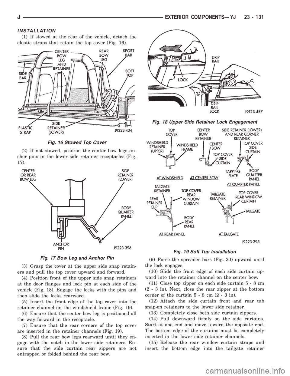
(1) If stowed at the rear of the vehicle, detach the
elastic straps that retain the top cover (Fig. 16).
(2) If not stowed, position the center bow legs an-
chor pins in the lower side retainer receptacles (Fig.
17).
(3) Grasp the cover at the upper side snap retain-
ers and pull the top cover upward and forward.
(4) Position front of the upper side snap retainers
at the door flanges and lock pin at each side of the
vehicle (Fig. 18). Engage the locks with the pins and
then slide the locks rearward.
(5) Insert the front edge of the top cover into the
retainer channel on the windshield frame (Fig. 19).
(6) Ensure that the center bow leg is positioned all
the way forward in the receptacle.
(7) Ensure that the rear corners of the top cover
are inserted in the retainer channels (Fig. 19).
(8) Pull the rear bow legs rearward until they en-
gage with the notch in the lower side retainers. En-
sure that the side curtain rear zippers are not
entrapped or folded behind the rear bow.(9) Force the spreader bars (Fig. 20) upward until
the lock engages.
(10) Slide the front edge of each side curtain up-
ward into the retainer channel on the center bow.
(11) Close top zipper on each side curtain5-8cm
(2 - 3 in). Next, close the rear zipper at the bottom
corner of the curtain5-8cm(2-3in).
(12) Attach the side curtain front and rear tab
snap-on retainers to the lower side retainer.
(13) Completely close both side curtain zippers.
(14) Pull downward firmly on the side curtains.
Start at one end and move toward the opposite end.
The bottom edge of the curtains must be completely
inserted in the lower side retainer channels.
(15) Release the rear window curtain straps and
insert the bottom edge into the tailgate retainer
Fig. 16 Stowed Top Cover
Fig. 17 Bow Leg and Anchor Pin
Fig. 18 Upper Side Retainer Lock Engagement
Fig. 19 Soft Top Installation
JEXTERIOR COMPONENTSÐYJ 23 - 131