1995 JEEP YJ oil filter
[x] Cancel search: oil filterPage 1667 of 2158
(7) Align valve body and seat it on case. Be sure
manual lever shaft and accumulator spring are prop-
erly seated.
(8) Hold valve body in position and install one or
two attaching bolts to hold valve body in place.
(9) Install remaining valve body bolts. Tighten all
bolts evenly in a diagonal pattern to 12 Nzm (105 in-
lbs) torque.
(10) Install new oil filter and tighten filter screws
to4Nzm (35 in. lbs.) torque.
(11) Connect converter solenoid wire to case con-
nector.
(12) Install manual and throttle levers on throttle
lever shaft. Tighten lever clamp screws and check for
free operation. Shaft and levers must operate freely
without any bind.
(13) Install oil pan and new gasket. Tighten pan
bolts to 17 Nzm (13 ft. lbs.) torque.
(14) Install seal on neutral switch, install switch in
case, and connect switch wires.
(15) Lower vehicle.
(16) Fill transmission with Mopar ATF Plus, Type
7176 fluid.
(17) Adjust gearshift linkage and throttle valve
(kickdown) cable if necessary.
GOVERNOR AND PARK GEAR SERVICE
GOVERNOR/PARK GEAR REMOVAL
(1) Raise vehicle.
(2) Mark both propeller shaft yokes for assembly
reference and disconnect propeller shafts at transfer
case.
(3) Disconnect speed sensor wires and remove
speedometer adapter and sensor.
(4) Position support stand under transmission con-
verter housing.
(5) Remove rear crossmember.
(6) Disconnect parking brake cable at equalizer
and disconnect exhaust components as necessary.
(7) Support transfer case with jack.
(8) Remove bolts attaching transfer case to trans-
mission adapter housing and remove transfer case.
(9) Remove bolts attaching adapter, or extension
housing to transmission and remove adapter/housing.
(10) Loosen but do not remove bolts that attach
governor body to park gear.
(11) Rotate transmission output shaft until gover-
nor weight assembly is accessible. Then remove
E-clip at this end of governor shaft.
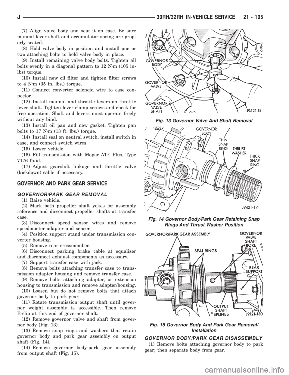
(12) Remove governor valve and shaft from gover-
nor body (Fig. 13).
(13) Remove snap rings and washers that retain
governor body and park gear assembly on output
shaft (Fig. 14).
(14) Remove governor body-park gear assembly
from output shaft (Fig. 15).
GOVERNOR BODY/PARK GEAR DISASSEMBLY
(1) Remove bolts attaching governor body to park
gear; then separate body from gear.
Fig. 13 Governor Valve And Shaft Removal
Fig. 14 Governor Body/Park Gear Retaining Snap
Rings And Thrust Washer Position
Fig. 15 Governor Body And Park Gear Removal/
Installation
J30RH/32RH IN-VEHICLE SERVICE 21 - 105
Page 1692 of 2158
if damaged. Inspect the park gear for chipped or
worn gear teeth or damaged ring grooves. Replace
the gear, if damaged.
Check the teeth on the park gear for wear or dam-
age. Replace the gear if necessary. Inspect the metal
seal rings on the park gear hub. Replace the rings
only if severely worn, or broken.
Minor scratches, or burrs on governor components
can be cleaned up with oil-soaked crocus cloth. How-
ever, do not attempt to salvage components that are
severely worn or scored.
The governor valve is made of aluminum and
the output shaft has been spotfaced to accept
the valve. The aluminum valve must not be
used in prior transmissions. The valve can only
be used with an output shaft that has been
spotfaced for valve end clearance. In addition,
the governor body and output shaft must be
properly indexed during reassembly. Be sure to
index these components as described in the
Transmission Assembly and Adjustment proce-
dures.
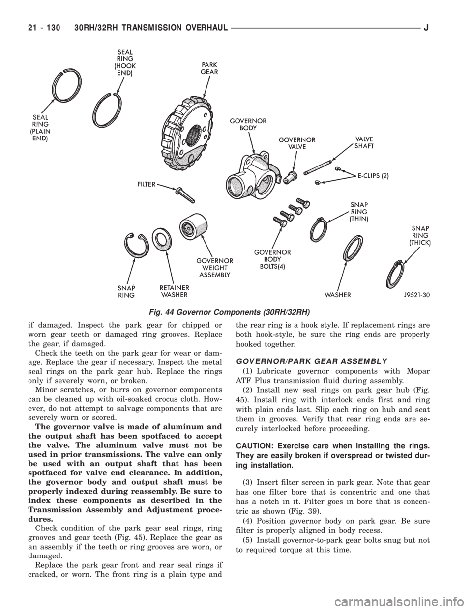
Check condition of the park gear seal rings, ring
grooves and gear teeth (Fig. 45). Replace the gear as
an assembly if the teeth or ring grooves are worn, or
damaged.
Replace the park gear front and rear seal rings if
cracked, or worn. The front ring is a plain type andthe rear ring is a hook style. If replacement rings are
both hook-style, be sure the ring ends are properly
hooked together.
GOVERNOR/PARK GEAR ASSEMBLY
(1) Lubricate governor components with Mopar
ATF Plus transmission fluid during assembly.
(2) Install new seal rings on park gear hub (Fig.
45). Install ring with interlock ends first and ring
with plain ends last. Slip each ring on hub and seat
them in grooves. Verify that rear ring ends are se-
curely interlocked before proceeding.
CAUTION: Exercise care when installing the rings.
They are easily broken if overspread or twisted dur-
ing installation.
(3) Insert filter screen in park gear. Note that gear
has one filter bore that is concentric and one that
has a notch in it. Filter goes in bore that is concen-
tric as shown (Fig. 39).
(4) Position governor body on park gear. Be sure
filter is properly aligned in body recess.
(5) Install governor-to-park gear bolts snug but not
to required torque at this time.
Fig. 44 Governor Components (30RH/32RH)
21 - 130 30RH/32RH TRANSMISSION OVERHAULJ
Page 1725 of 2158
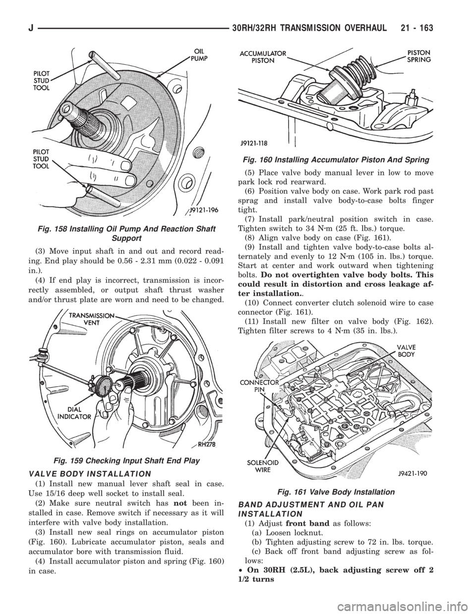
(3) Move input shaft in and out and record read-
ing. End play should be 0.56 - 2.31 mm (0.022 - 0.091
in.).
(4) If end play is incorrect, transmission is incor-
rectly assembled, or output shaft thrust washer
and/or thrust plate are worn and need to be changed.
VALVE BODY INSTALLATION
(1) Install new manual lever shaft seal in case.
Use 15/16 deep well socket to install seal.
(2) Make sure neutral switch hasnotbeen in-
stalled in case. Remove switch if necessary as it will
interfere with valve body installation.
(3) Install new seal rings on accumulator piston
(Fig. 160). Lubricate accumulator piston, seals and
accumulator bore with transmission fluid.
(4) Install accumulator piston and spring (Fig. 160)
in case.(5) Place valve body manual lever in low to move
park lock rod rearward.
(6) Position valve body on case. Work park rod past
sprag and install valve body-to-case bolts finger
tight.
(7) Install park/neutral position switch in case.
Tighten switch to 34 Nzm (25 ft. lbs.) torque.
(8) Align valve body on case (Fig. 161).
(9) Install and tighten valve body-to-case bolts al-
ternately and evenly to 12 Nzm (105 in. lbs.) torque.
Start at center and work outward when tightening
bolts.Do not overtighten valve body bolts. This
could result in distortion and cross leakage af-
ter installation..
(10) Connect converter clutch solenoid wire to case
connector (Fig. 161).
(11) Install new filter on valve body (Fig. 162).
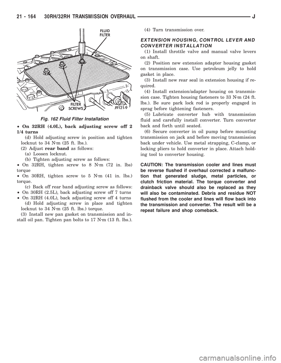
Tighten filter screws to 4 Nzm (35 in. lbs.).
BAND ADJUSTMENT AND OIL PAN
INSTALLATION
(1) Adjustfront bandas follows:
(a) Loosen locknut.
(b) Tighten adjusting screw to 72 in. lbs. torque.
(c) Back off front band adjusting screw as fol-
lows:
²On 30RH (2.5L), back adjusting screw off 2
1/2 turns
Fig. 158 Installing Oil Pump And Reaction Shaft
Support
Fig. 159 Checking Input Shaft End Play
Fig. 160 Installing Accumulator Piston And Spring
Fig. 161 Valve Body Installation
J30RH/32RH TRANSMISSION OVERHAUL 21 - 163
Page 1726 of 2158
²On 32RH (4.0L), back adjusting screw off 2
1/4 turns
(d) Hold adjusting screw in position and tighten
locknut to 34 Nzm (25 ft. lbs.).
(2) Adjustrear bandas follows:
(a) Loosen locknut.
(b) Tighten adjusting screw as follows:
²On 32RH, tighten screw to 8 Nzm (72 in. lbs)
torque
²On 30RH, tighten screw to 5 Nzm (41 in. lbs.)
torque.
(c) Back off rear band adjusting screw as follows:
²On 30RH (2.5L), back adjusting screw off 7 turns
²On 32RH (4.0L), back adjusting screw off 4 turns
(d) Hold adjusting screw in place and tighten
locknut to 34 Nzm (25 ft. lbs.) torque.
(3) Install new pan gasket on transmission and in-
stall oil pan. Tighten pan bolts to 17 Nzm (13 ft. lbs.).(4) Turn transmission over.
EXTENSION HOUSING, CONTROL LEVER AND
CONVERTER INSTALLATION
(1) Install throttle valve and manual valve levers
on shaft.
(2) Position new extension adapter housing gasket
on transmission case. Use petroleum jelly to hold
gasket in place.
(3) Install new rear seal in extension housing if re-
quired.
(4) Install extension/adapter housing on transmis-
sion case. Tighten housing fasteners to 33 Nzm (24 ft.
lbs.). Be sure park lock rod is properly engaged in
sprag before tightening fasteners.
(5) Lubricate converter hub with transmission
fluid and carefully install converter. Turn converter
back and forth until seated.
(6) Secure converter in oil pump before mounting
transmission on jack and before moving transmission
back under vehicle. Use metal strapping, C-clamp, or
locking pliers to hold converter in place. Attach hold-
ing tool to converter housing.
CAUTION: The transmission cooler and lines must
be reverse flushed if overhaul corrected a malfunc-
tion that generated sludge, metal particles, or
clutch friction material. The torque converter and
drainback valve should also be replaced as they
will also be contaminated. Debris and residue NOT
flushed from the cooler and lines will flow back into
the transmission and converter. The result will be a
repeat failure and shop comeback.
Fig. 162 Fluid Filter Installation
21 - 164 30RH/32RH TRANSMISSION OVERHAULJ
Page 1744 of 2158
AW-4 IN-VEHICLE SERVICE
INDEX
page page
Accumulator Pistons and Springs............. 189
Adapter Housing Seal Replacement........... 191
Checking Fluid Level and Condition........... 182
Manual Valve Shaft Seal Replacement......... 187
Park Interlock Cable Adjustment............. 195
Park Rod and Pawl Service................. 190
Park/Neutral Position Switch................ 183
Refilling After Overhaul or Fluid/Filter Change . . . 182
Second Coast Brake Servo................. 190
Shift Cable Adjustment.................... 195
Speed Sensor........................... 192Speed Sensor RotorÐSpeedometer Drive Gear . . 193
Throttle Position Sensor (TPS) Service........ 193
Transmission Control Module (TCM) Service.... 183
Transmission Cooler Line Fittings............ 197
Transmission Cooler Service................ 196
Transmission Throttle Cable Adjustment........ 194
Transmission Throttle Cable Replacement...... 193
Transmission Valve Body Installation.......... 187
Transmission Valve Body Removal........... 186
Transmission Valve Body Solenoids........... 184
CHECKING FLUID LEVEL AND CONDITION
Recommended fluid for AW-4 transmissions is Mo-
par Dexron IIE/Mercon.
Mopar Dexron II can also be used but only when
Mercon fluid is not available.
CHECKING FLUID LEVEL
(1) Be sure transmission fluid is at normal operat-
ing temperature. Normal operating temperature is
reached after approximately 15 miles (25 km) of op-
eration.
(2) Position vehicle on level surface. This is impor-
tant for an accurate fluid level check.
(3) Shift transmission through all gear ranges and
back to Park.
(4) Apply parking brakes.
(5) Verify that transmission is in Park.
(6) Wipe off dipstick handle to prevent dirt from
entering fill tube. Then remove dipstick and check
fluid level and condition.
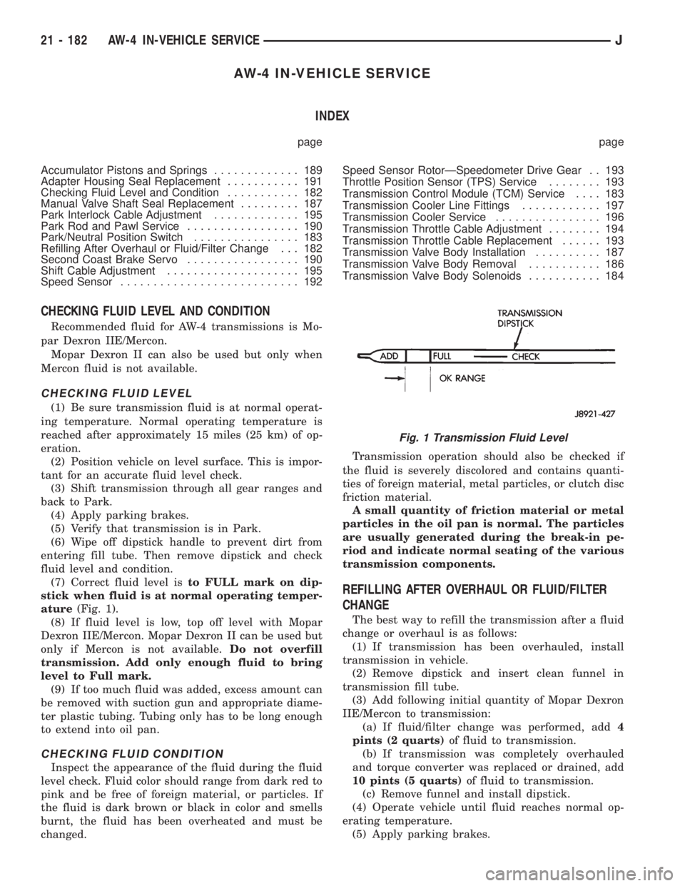
(7) Correct fluid level isto FULL mark on dip-
stick when fluid is at normal operating temper-
ature(Fig. 1).
(8) If fluid level is low, top off level with Mopar
Dexron IIE/Mercon. Mopar Dexron II can be used but
only if Mercon is not available.Do not overfill
transmission. Add only enough fluid to bring
level to Full mark.
(9) If too much fluid was added, excess amount can
be removed with suction gun and appropriate diame-
ter plastic tubing. Tubing only has to be long enough
to extend into oil pan.
CHECKING FLUID CONDITION
Inspect the appearance of the fluid during the fluid
level check. Fluid color should range from dark red to
pink and be free of foreign material, or particles. If
the fluid is dark brown or black in color and smells
burnt, the fluid has been overheated and must be
changed.Transmission operation should also be checked if
the fluid is severely discolored and contains quanti-
ties of foreign material, metal particles, or clutch disc
friction material.
A small quantity of friction material or metal
particles in the oil pan is normal. The particles
are usually generated during the break-in pe-
riod and indicate normal seating of the various
transmission components.
REFILLING AFTER OVERHAUL OR FLUID/FILTER
CHANGE
The best way to refill the transmission after a fluid
change or overhaul is as follows:
(1) If transmission has been overhauled, install
transmission in vehicle.
(2) Remove dipstick and insert clean funnel in
transmission fill tube.
(3) Add following initial quantity of Mopar Dexron
IIE/Mercon to transmission:
(a) If fluid/filter change was performed, add4
pints (2 quarts)of fluid to transmission.
(b) If transmission was completely overhauled
and torque converter was replaced or drained, add
10 pints (5 quarts)of fluid to transmission.
(c) Remove funnel and install dipstick.
(4) Operate vehicle until fluid reaches normal op-
erating temperature.
(5) Apply parking brakes.
Fig. 1 Transmission Fluid Level
21 - 182 AW-4 IN-VEHICLE SERVICEJ
Page 1746 of 2158
(2) Rotate manual shift lever all the way rearward.
Then rotate lever forward two detent positions to
Neutral.
(3) Install switch on manual valve shaft and in-
stall switch adjusting bolt finger tight. Do not tighten
bolt at this time.
(4) Install tabbed washer on manual valve shaft
and install switch attaching nut. Tighten nut to 6.9
Nzm (61 in. lbs.) torque but do not bend washer lock
tabs over nut at this time.
(5) Verify that transmission is in Neutral.
(6) Rotate switch to align neutral standard line
with vertical groove on manual valve shaft (Fig. 6).
(7) Align switch standard line with groove or flat
on manual valve shaft.
(8) Tighten switch adjusting bolt to 13 Nzm(9ft.
lbs.) torque.
(9) Bend at least two washer lock tabs over switch
attaching nut to secure it.
(10) Connect shift linkage rod to shift lever on left
side of case.
(11) Connect switch wires to harness and lower ve-
hicle.
(12) Check switch operation. Engine should start
in Park and Neutral only.
TRANSMISSION VALVE BODY SOLENOIDS
SOLENOID REMOVAL
(1) Remove transmission oil pan drain plug and
drain fluid.
(2) Remove pan bolts and remove oil pan.(3) Remove oil screen bolts and remove screen (Fig.
7) and gasket. Discard the gasket.
(4) Disconnect solenoid wire connector (Fig. 8).
(5) If all solenoids are being removed, mark or tag
wires for assembly reference before disconnecting
them.
(6) Remove bolt attaching solenoids to valve body
and remove solenoids (Fig. 9). Do not allow any valve
body components to fall out when solenoids are re-
moved.
(7) Clean oil filter and pan with solvent and dry
with compressed air.
(8) Remove old sealer material from oil pan and
transmission case.
Fig. 5 Park/Neutral Position Switch Removal/
Installation
Fig. 6 Park/Neutral Position Switch Adjustment
Fig. 7 Oil Screen Removal/Installation
21 - 184 AW-4 IN-VEHICLE SERVICEJ
Page 2087 of 2158
EVAPORATOR COIL:The coil is located in the
A/C housing. Its function is to remove heat and de-
humidify the air before it enters the vehicle.
FIN SENSING CYCLING CLUTCH SWITCH:
The switch is attached to the evaporator coil with the
temperature sensing probe inserted into the coil fins.
This switch controls evaporator temperature and pre-
vents condensate water on the evaporator coil from
freezing. It does this by sending signals to the Pow-
ertrain Control Module (PCM) to cycling the com-
pressor clutch on and off. This switch is used onXJ
only.
FILTER-DRIER:The drier is used to remove any
traces of moisture from the refrigerant system. A
sight glass is located on top of the filter drier. It is
used as a diagnostic tool to observe refrigerant flow.
HIGH PRESSURE RELIEF VALVE:The valve is
located on the filter drier. The valve is used to pre-
vent excessive high pressure build of 3445 to 4135
kPa (500 to 600 psi) and above. This prevents dam-
age to the compressor and other system components.
LOW-PRESSURE HIGH-PRESSURE CUT-OFF
SWITCH:The switch is located on the filter drier
and is wired in series with compressor clutch. When
the pressure drops down to 193 kPa (28 psi) the
switch interrupts the power to the compressor clutch.
When the pressure increases above 3100 to 3375 kPa
(450 to 490 psi) the switch interrupts the power to
the compressor clutch.
THERMOSTAT:The thermostat is located in the
evaporator housing. The thermostat temperature
sensing probe is inserted into the evaporator coil. Its
function is to cycles the compressor clutch on and off.
This switch controls temperature and prevents con-
densate water on the evaporator coil from freezing.
The thermostat is used on theYJonly.
REFRIGERANT LINES:The lines are used to
carry the refrigerant between the various system
components.
SERVICE PORTS:The high pressure service port
is located on the discharge line near the compressor.
The low pressure service port is located on the suc-
tion line near the compressor. These ports are used
to attach A/C gauges. After servicing the refrigerant
system, always install service port caps.
REFRIGERANT
XJ and YJ vehicles use a new type of refrigerant
called R-134a. It is a non-toxic, non-flammable, clear
color-less liquified gas.
R-134a refrigerant is not compatible with R-12 re-
frigerant. A small amount of R-12 in a R-134a system
will cause compressor failure, oil sludge or poor air
conditioning performance.R-134a refrigerant requires a special type of com-
pressor oil (SP20 PAG). When adding oil, make sure
that it is designed to be used in a R-134a system and
the SD7H15 compressor.
Service ports have been designed to ensure that
the system is not accidentally filled with R-12 refrig-
erant.
REFRIGERANT EQUIPMENT
WARNING: EYE PROTECTION MUST BE USED
WHEN SERVICING AN AIR CONDITIONING REFRIG-
ERANT SYSTEM. TURN OFF (ROTATE CLOCKWISE)
ALL VALVES ON THE EQUIPMENT BEING USED
BEFORE PROCEEDING WITH THIS OPERATION.
PERSONNEL INJURY CAN RESULT.
Chrysler Corporation recommends a (R-134a) recy-
cling device that meets SAE standard J2210 be used
when servicing the refrigerant system. Contact an
automotive service equipment supplier for refrigerant
recycling equipment that is available in your area.
Refer to the operating instructions provided with the
recycling equipment for proper operation.
MANIFOLD GAUGE SET
CAUTION: DO NOT use an R-12 manifold gauge set
on an R-134a system. The refrigerants are not com-
patible and system damage will result.
A manifold gauge set (Fig. 1) may be needed in
conjunction with the charging and or recovery/recy-
cling device. The service hoses on the gauge set being
used should have manual (turn wheel) or automatic
back flow valves at the service port connector ends.
This will prevent refrigerant from being release into
the atmosphere.
LOW PRESSURE GAUGE HOSE
The low pressure hose (BLUE with BLACK STRIP)
should be attached to the charging/service port. This
port is located at the right front of the engine com-
partment in the condenser-to-evaporator line.
HIGH PRESSURE GAUGE HOSE
The high pressure hose (RED with BLACK STRIP)
should be attached to the discharge/service port. This
port is located on the compressor plumbing or mani-
fold.
RECOVERY/RECYCLING/EVACUATION/
CHARGING HOSE
The center manifold hose (YELLOW or WHITE
with BLACK STRIP) is used to recover, evacuate and
charge the refrigerant system. When the low or high
pressure valves on the manifold gauge set are
opened, the refrigerant in the system will escape
through this hose.
JHEATING AND AIR CONDITIONING 24 - 7
Page 2095 of 2158
HEATING AND AIR CONDITIONING TEST PROCEDURES
INDEX
page page
A/C Compressor Clutch..................... 15
A/C Compressor Clutch Relay................ 15
A/C Compressor Clutch Relay................ 16
Air Conditioning ControlsÐXJ Vehicles......... 15
Air Conditioning ControlsÐYJ Vehicles......... 16
Blower Motor............................ 17
Blower Motor Switch....................... 16Compressor Clutch........................ 16
Fin Sensing Cycling Clutch Switch............. 15
Heater Diagnosis......................... 17
Low-Pressure High-Pressure Cut-Off Switch..... 15
Low-Pressure High-Pressure Cut-Off Switch..... 16
Thermostatic Control....................... 16
AIR CONDITIONING CONTROLSÐXJ VEHICLES
The A/C Compressor Clutch is controlled by several
components: the Pressure Cut-Off Switch, Cycling
Clutch Switch, Clutch Relay and Powertrain Control
Module (PCM).
Powertrain Control Module may delay A/C clutch
engagement up to 30 seconds.
Refer to Group 8W Wiring Diagrams for wiring and
terminals. Use volt ohmmeter to test switches.
A/C COMPRESSOR CLUTCH
The clutch assembly consists of a stationary elec-
tromagnetic coil, hub bearing pulley assembly, and
clutch plate. When the coil is energized the plate is
magnetically engaged with the pulley and turns the
compressor shaft.
A/C COMPRESSOR CLUTCH TEST
(1) Unplug clutch coil connector.
(2) Connect a jumper wire from the battery posi-
tive post to the clutch coil terminal. The clutch
should engage, if not leave jumper wire connected
and go to next step.
(3) Connect a jumper wire from clutch coil frame to
chassis ground. The clutch should engage if not re-
pair clutch coil ground or replace coil.
A/C COMPRESSOR CLUTCH RELAY
The A/C compressor clutch relay controls the 12-
volt source to the A/C clutch. The relay is activated
when the PCM receives a A/C request signal from the
fin-sensed cycling clutch switch. The PCM then sends
a ground signal to the relay. The relay is activated
and sends 12-volts to the clutch coil which energizes
the clutch. The relay is located in the power distribu-
tion center.
COMPRESSOR CLUTCH RELAY TEST
For test procedure refer to Powertrain Diagnostic
Service Manual for A/C clutch relay circuit test.
LOW-PRESSURE HIGH-PRESSURE CUT-OFF
SWITCH
The pressure cut-off switch is located on the filter
drier and is wired in series with compressor clutch.
The switch interrupts the power to the compressor
clutch circuit when the pressure drops to 193 kPa (28
psi) or increases above 3100 to 3375 kPa (450 to 490
psi).
PRESSURE CUT-OFF SWITCH TEST
(1) Verify system has correct refrigerant charge.
(2) Turn ignition switch to RUN, A/C blower switch
to ON and control set to MAX.
(3) Unplug pressure cut-off switch and test feed
circuit from select switch. It should be battery volt-
age if not, repair open to select switch.
(4) Test for continuity between the switch termi-
nals. If continuity is not present recover refrigerant
from the system. Replace switch, evacuate and re-
charge system.
FIN SENSING CYCLING CLUTCH SWITCH
The switch is attached to the evaporator coil with
the temperature sensing probe inserted into the coil
fins. This switch prevents condensate water on the
evaporator coil from freezing. It does this by sending
signals to the PCM to cycling the compressor clutch
on and off.
FIN-SENSED CYCLING CLUTCH SWITCH TEST
Test area ambient temperature should be around
21ÉC (70ÉF) for test.
(1) Verify system has correct refrigerant charge.
(2) Start Engine and turn on A/C.
(3) If the compressor clutch cycles ON and OFF 2
to 3 times per minute the cycling clutch switch is
normal. The ambient temperature should be between
20ÉC-30ÉC (68ÉF-90ÉF). Above 32ÉC (90ÉF) the com-
pressor clutch may stay engaged (non cycling) due to
the high heat load, this condition is normal. If the
compressor clutch fails to engage go to next step.
(4) Disconnect wiring harness connector from
switch. With a volt meter test feed circuit from cut-
JHEATING AND AIR CONDITIONING 24 - 15