1995 JEEP YJ automatic transmission fluid
[x] Cancel search: automatic transmission fluidPage 1676 of 2158
(3) If vehicle is equipped withauxiliary cooler,
test cooler flow as described in step (2).
TRANSMISSION COOLER REVERSE FLUSHING
The flushing procedure applies to standard and
auxiliary coolers alike. Although pressure equipment
is preferred, reverse flushing can be performed with
hand operated equipment as follows.
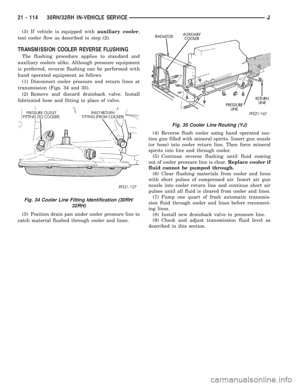
(1) Disconnect cooler pressure and return lines at
transmission (Figs. 34 and 35).
(2) Remove and discard drainback valve. Install
fabricated hose and fitting in place of valve.
(3) Position drain pan under cooler pressure line to
catch material flushed through cooler and lines.(4) Reverse flush cooler using hand operated suc-
tion gun filled with mineral spirits. Insert gun nozzle
(or hose) into cooler return line. Then force mineral
spirits into line and through cooler.
(5) Continue reverse flushing until fluid coming
out of cooler pressure line is clear.Replace cooler if
fluid cannot be pumped through.
(6) Clear flushing materials from cooler and lines
with short pulses of compressed air. Insert air gun
nozzle into cooler return line and continue short air
pulses until all fluid is cleared from cooler and lines.
(7) Pump one quart of fresh automatic transmis-
sion fluid through cooler and lines before reconnect-
ing lines.
(8) Install new drainback valve in pressure line.
(9) Check and adjust transmission fluid level as
described in this section.
Fig. 34 Cooler Line Fitting Identification (30RH/
32RH)
Fig. 35 Cooler Line Routing (YJ)
21 - 114 30RH/32RH IN-VEHICLE SERVICEJ
Page 1727 of 2158
AW-4 AUTOMATIC TRANSMISSION
CONTENTS
page page
AW-4 AUTOMATIC TRANSMISSION........ 165
AW-4 IN-VEHICLE SERVICE.............. 182
AW-4 TRANSMISSION DIAGNOSIS......... 176
AW-4 TRANSMISSION OVERHAUL......... 201AW-4 TRANSMISSION REMOVAL AND
INSTALLATION....................... 198
GENERAL INFORMATION................ 165
GENERAL INFORMATION
INDEX
page page
Components and Operation................. 166
Description............................. 165
First/Second/Third/Reverse Components....... 168
Fourth Gear Overdrive Components.......... 167
Geartrain Operation and Application Charts..... 169Hydraulic System........................ 169
Recommended Fluid and Capacity........... 166
Torque Converter........................ 167
Transmission Identification.................. 166
Transmission Ranges and Shift Lever Positions . . 166
DESCRIPTION
AW-4 Transmission Overhaul
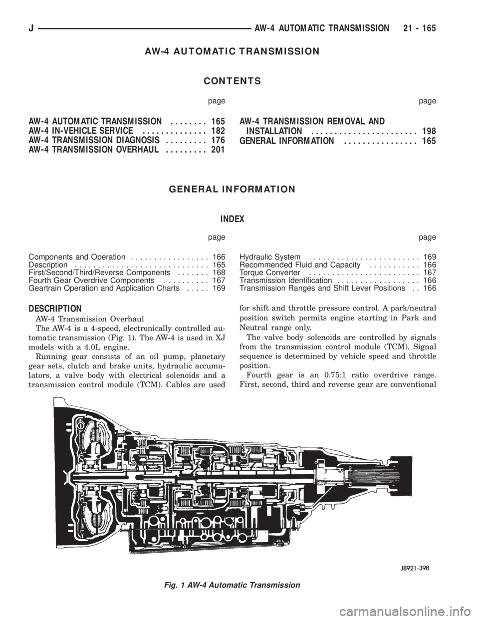
The AW-4 is a 4-speed, electronically controlled au-
tomatic transmission (Fig. 1). The AW-4 is used in XJ
models with a 4.0L engine.
Running gear consists of an oil pump, planetary
gear sets, clutch and brake units, hydraulic accumu-
lators, a valve body with electrical solenoids and a
transmission control module (TCM). Cables are usedfor shift and throttle pressure control. A park/neutral
position switch permits engine starting in Park and
Neutral range only.
The valve body solenoids are controlled by signals
from the transmission control module (TCM). Signal
sequence is determined by vehicle speed and throttle
position.
Fourth gear is an 0.75:1 ratio overdrive range.
First, second, third and reverse gear are conventional
Fig. 1 AW-4 Automatic Transmission
JAW-4 AUTOMATIC TRANSMISSION 21 - 165
Page 1728 of 2158
ranges. Third gear ratio is 1:1. A separate planetary
gear set provides overdrive operation in fourth gear.
TRANSMISSION RANGES AND SHIFT LEVER
POSITIONS
The AW-4 transmission has six ranges and shift le-
ver positions. Park, Reverse and Neutral are conven-
tional and mechanically operated. The 1-2, 3 and D
ranges provide electronically controlled shifting.
The 1-2 position provides first and second gear
only. The 3 position provides first, second and third
gear.
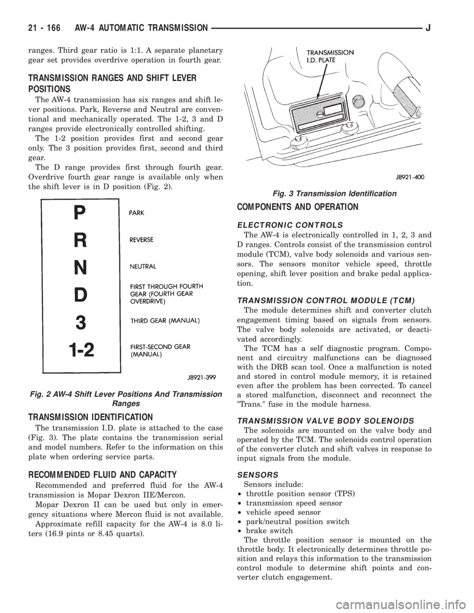
The D range provides first through fourth gear.
Overdrive fourth gear range is available only when
the shift lever is in D position (Fig. 2).
TRANSMISSION IDENTIFICATION
The transmission I.D. plate is attached to the case
(Fig. 3). The plate contains the transmission serial
and model numbers. Refer to the information on this
plate when ordering service parts.
RECOMMENDED FLUID AND CAPACITY
Recommended and preferred fluid for the AW-4
transmission is Mopar Dexron IIE/Mercon.
Mopar Dexron II can be used but only in emer-
gency situations where Mercon fluid is not available.
Approximate refill capacity for the AW-4 is 8.0 li-
ters (16.9 pints or 8.45 quarts).
COMPONENTS AND OPERATION
ELECTRONIC CONTROLS
The AW-4 is electronically controlled in 1, 2, 3 and
D ranges. Controls consist of the transmission control
module (TCM), valve body solenoids and various sen-
sors. The sensors monitor vehicle speed, throttle
opening, shift lever position and brake pedal applica-
tion.
TRANSMISSION CONTROL MODULE (TCM)
The module determines shift and converter clutch
engagement timing based on signals from sensors.
The valve body solenoids are activated, or deacti-
vated accordingly.
The TCM has a self diagnostic program. Compo-
nent and circuitry malfunctions can be diagnosed
with the DRB scan tool. Once a malfunction is noted
and stored in control module memory, it is retained
even after the problem has been corrected. To cancel
a stored malfunction, disconnect and reconnect the
9Trans.9fuse in the module harness.
TRANSMISSION VALVE BODY SOLENOIDS
The solenoids are mounted on the valve body and
operated by the TCM. The solenoids control operation
of the converter clutch and shift valves in response to
input signals from the module.
SENSORS
Sensors include:
²throttle position sensor (TPS)
²transmission speed sensor
²vehicle speed sensor
²park/neutral position switch
²brake switch
The throttle position sensor is mounted on the
throttle body. It electronically determines throttle po-
sition and relays this information to the transmission
control module to determine shift points and con-
verter clutch engagement.
Fig. 2 AW-4 Shift Lever Positions And Transmission
Ranges
Fig. 3 Transmission Identification
21 - 166 AW-4 AUTOMATIC TRANSMISSIONJ
Page 1732 of 2158

The manual valve, 1-2 shift valve, primary regula-
tor valve, accumulator control valve, check balls, so-
lenoids and oil strainers are located in the lower
body section (Fig. 10). The remaining control and
shift valves plus check balls and one additional oil
strainer are located in the upper body section (Fig.
11).
Manual Valve
The manual valve is operated by the gearshift link-
age. The valve diverts fluid to the apply circuits ac-
cording to shift lever position.Primary Regulator Valve
The primary regulator valve (Fig. 13) modulates
line pressure to the clutches and brakes according to
engine load. The valve is actuated by throttle valve
pressure.
During high load operation, the valve increases line
pressure to maintain positive clutch and brake en-
gagement. At light load, the valve decreases line
pressure just enough to maintain smooth engage-
ment.
Fig. 10 Upper Body Components
Fig. 11 Lower Body Components
21 - 170 AW-4 AUTOMATIC TRANSMISSIONJ
Page 1734 of 2158
Secondary Regulator Valve
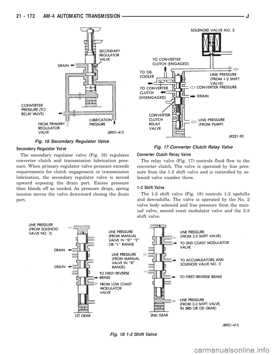
The secondary regulator valve (Fig. 16) regulates
converter clutch and transmission lubrication pres-
sure. When primary regulator valve pressure exceeds
requirements for clutch engagement or transmission
lubrication, the secondary regulator valve is moved
upward exposing the drain port. Excess pressure
then bleeds off as needed. As pressure drops, spring
tension moves the valve downward closing the drain
port.Converter Clutch Relay Valve
The relay valve (Fig. 17) controls fluid flow to the
converter clutch. The valve is operated by line pres-
sure from the 1-2 shift valve and is controlled by so-
lenoid valve number three.
1-2 Shift Valve
The 1-2 shift valve (Fig. 18) controls 1-2 upshifts
and downshifts. The valve is operated by the No. 2
valve body solenoid and line pressure from the man-
ual valve, second coast modulator valve and the 2-3
shift valve.
Fig. 16 Secondary Regulator Valve
Fig. 17 Converter Clutch Relay Valve
Fig. 18 1-2 Shift Valve
21 - 172 AW-4 AUTOMATIC TRANSMISSIONJ
Page 1759 of 2158
the front bumper and radiator support be removed
for access to the cooler lines and attaching bracket.
REVERSE FLUSHING MAIN AND AUXILIARY
COOLERS AND COOLER LINES
Reverse flushing the cooler and lines will prevent
sludge and particles from flowing back into the
transmission after repair. The flushing procedure ap-
plies to standard (in-radiator) coolers and auxiliary
coolers equally.
Pressure equipment is preferred for reverse flush-
ing. However, reverse flushing can be performed us-
ing hand operated equipment as described in the
following procedure.
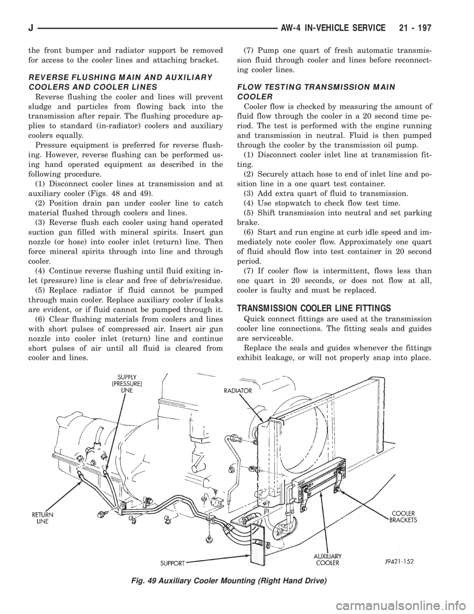
(1) Disconnect cooler lines at transmission and at
auxiliary cooler (Figs. 48 and 49).
(2) Position drain pan under cooler line to catch
material flushed through coolers and lines.
(3) Reverse flush each cooler using hand operated
suction gun filled with mineral spirits. Insert gun
nozzle (or hose) into cooler inlet (return) line. Then
force mineral spirits through into line and through
cooler.
(4) Continue reverse flushing until fluid exiting in-
let (pressure) line is clear and free of debris/residue.
(5) Replace radiator if fluid cannot be pumped
through main cooler. Replace auxiliary cooler if leaks
are evident, or if fluid cannot be pumped through it.
(6) Clear flushing materials from coolers and lines
with short pulses of compressed air. Insert air gun
nozzle into cooler inlet (return) line and continue
short pulses of air until all fluid is cleared from
cooler and lines.(7) Pump one quart of fresh automatic transmis-
sion fluid through cooler and lines before reconnect-
ing cooler lines.
FLOW TESTING TRANSMISSION MAIN
COOLER
Cooler flow is checked by measuring the amount of
fluid flow through the cooler in a 20 second time pe-
riod. The test is performed with the engine running
and transmission in neutral. Fluid is then pumped
through the cooler by the transmission oil pump.
(1) Disconnect cooler inlet line at transmission fit-
ting.
(2) Securely attach hose to end of inlet line and po-
sition line in a one quart test container.
(3) Add extra quart of fluid to transmission.
(4) Use stopwatch to check flow test time.
(5) Shift transmission into neutral and set parking
brake.
(6) Start and run engine at curb idle speed and im-
mediately note cooler flow. Approximately one quart
of fluid should flow into test container in 20 second
period.
(7) If cooler flow is intermittent, flows less than
one quart in 20 seconds, or does not flow at all,
cooler is faulty and must be replaced.
TRANSMISSION COOLER LINE FITTINGS
Quick connect fittings are used at the transmission
cooler line connections. The fitting seals and guides
are serviceable.
Replace the seals and guides whenever the fittings
exhibit leakage, or will not properly snap into place.
Fig. 49 Auxiliary Cooler Mounting (Right Hand Drive)
JAW-4 IN-VEHICLE SERVICE 21 - 197
Page 1762 of 2158
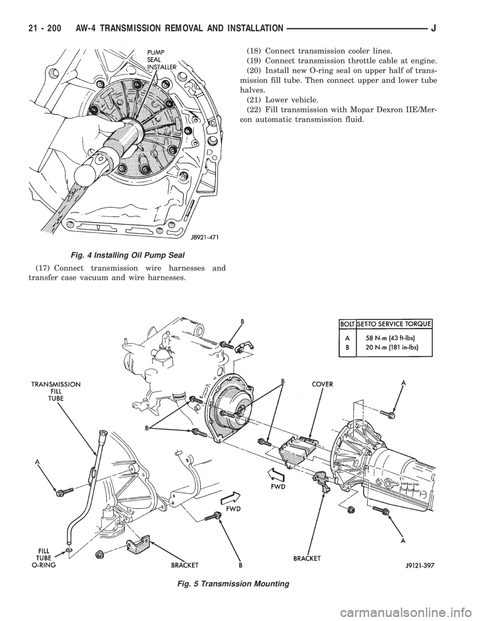
(17) Connect transmission wire harnesses and
transfer case vacuum and wire harnesses.(18) Connect transmission cooler lines.
(19) Connect transmission throttle cable at engine.
(20) Install new O-ring seal on upper half of trans-
mission fill tube. Then connect upper and lower tube
halves.
(21) Lower vehicle.
(22) Fill transmission with Mopar Dexron IIE/Mer-
con automatic transmission fluid.
Fig. 5 Transmission Mounting
Fig. 4 Installing Oil Pump Seal
21 - 200 AW-4 TRANSMISSION REMOVAL AND INSTALLATIONJ
Page 1776 of 2158
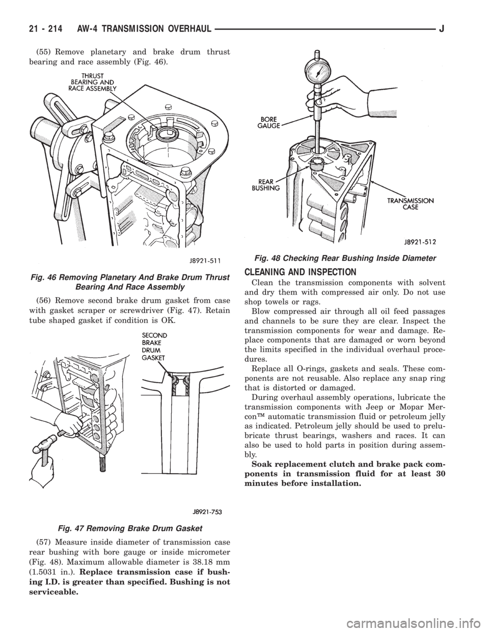
(55) Remove planetary and brake drum thrust
bearing and race assembly (Fig. 46).
(56) Remove second brake drum gasket from case
with gasket scraper or screwdriver (Fig. 47). Retain
tube shaped gasket if condition is OK.
(57) Measure inside diameter of transmission case
rear bushing with bore gauge or inside micrometer
(Fig. 48). Maximum allowable diameter is 38.18 mm
(1.5031 in.).Replace transmission case if bush-
ing I.D. is greater than specified. Bushing is not
serviceable.
CLEANING AND INSPECTION
Clean the transmission components with solvent
and dry them with compressed air only. Do not use
shop towels or rags.
Blow compressed air through all oil feed passages
and channels to be sure they are clear. Inspect the
transmission components for wear and damage. Re-
place components that are damaged or worn beyond
the limits specified in the individual overhaul proce-
dures.
Replace all O-rings, gaskets and seals. These com-
ponents are not reusable. Also replace any snap ring
that is distorted or damaged.
During overhaul assembly operations, lubricate the
transmission components with Jeep or Mopar Mer-
conŸ automatic transmission fluid or petroleum jelly
as indicated. Petroleum jelly should be used to prelu-
bricate thrust bearings, washers and races. It can
also be used to hold parts in position during assem-
bly.
Soak replacement clutch and brake pack com-
ponents in transmission fluid for at least 30
minutes before installation.Fig. 46 Removing Planetary And Brake Drum Thrust
Bearing And Race Assembly
Fig. 47 Removing Brake Drum Gasket
Fig. 48 Checking Rear Bushing Inside Diameter
21 - 214 AW-4 TRANSMISSION OVERHAULJ