1995 JEEP YJ 4 wheel drive
[x] Cancel search: 4 wheel drivePage 191 of 2158

original sensor bolt. Use new bolt if original is worn
or damaged.
(4) Install sensor bolt finger tight only at this time.
(5) Iforiginalrear sensor was installed, adjust
sensor air gap to 0.92-1.45 mm (0.036-0.057 in.). Use
feeler gauge to measure air gap (Fig. 10). Tighten
sensor bolt to 11 Nzm (11 ft. lbs.) torque.
(6) Ifnewsensor was installed, push cardboard
spacer on sensor face against tone ring (Fig. 11).
Then tighten sensor bolt to 8 Nzm (6 ft. lbs.) torque.
Correct air gap will be established as tone ring ro-
tates and peels spacer off sensor face.
(7) On YJ, connect rear sensor wires to connectors
at axle. On XJ, route sensor wires to rear seat area.
(8) Feed sensor wires through floorpan access hole
and seat sensor grommets in floorpan.
(9) Verify that rear sensor wires are secured to
rear brake hose and axle with clips. Verify that wire
is clear of rotating components.
(10) Install brake drum and wheel.
(11) Lower vehicle.
(12) On XJ, connect sensor wire to harness connec-
tor. Then reposition carpet and fold rear seat down.
ACCELERATION SWITCH REMOVAL
(1) On XJ models, tilt rear seat assembly forward
for access to sensor (Fig. 12).(2) On YJ models, move driver seat forward or
rearward for access to sensor and mounting bracket
(Fig. 12).
(3) Disconnect switch harness.
(4) On XJ models, remove screws attaching switch
to bracket. Then remove switch.
(5) On YJ models, remove screws attaching switch
bracket to floorpan. Then remove switch from
bracket.
ACCELERATION SWITCH INSTALLATION
(1) Note position of locating arrow on switch.
Switch must be positioned so arrow faces forward.
Fig. 10 Setting Air Gap On Original Rear Sensor
Fig. 11 Location Of Spacer On New Rear Sensor
Fig. 12 Acceleration Switch Mounting (XJ/YJ)
JABS OPERATION AND SERVICE 5 - 39
Page 204 of 2158

(4) Install new spring nuts on wheel studs.
(5) Install wheel and lower vehicle.
DISC BRAKE ROTOR THICKNESS
Rotor minimum usable thickness is 22.7 mm (0.89
in.). This dimension is either cast, or stamped on the
rotor hub, or outer edge.
Measure rotor thickness at the center of the brake-
shoe contact surface.
Replace the rotor if worn below minimum thick-
ness. Also replace the rotor if refinishing would re-
duce thickness below the allowable minimum.
DISC BRAKE ROTOR RUNOUT
Check rotor lateral runout whenever pedal pulsa-
tion, or rapid, uneven brakelining wear has occurred.
On 4-wheel drive models, the rotor must be se-
curely clamped to the hub to ensure an accurate
runout measurement. Secure the rotor with the
wheel nuts and 4 or 5 large diameter flat washers on
each stud as shown (Fig. 27).
Use a dial indicator to check lateral runout (Fig.
27).
Maximum allowable rotor lateral runout is 0.13
mm (0.005 in.).
Check lateral runout with a dial indicator (Fig. 28).
Excessive lateral runout will cause brake pedal pul-
sation and rapid, uneven wear of the brakeshoes.
Maximum allowable rotor runout for all models is
0.12 mm (0.005 in.).
DISC BRAKE ROTOR THICKNESS VARIATION
Variations in rotor thickness will cause pedal pul-
sation, noise and shudder.
Measure rotor thickness at four to six points
around the rotor face. Position the micrometer ap-
proximately 2 cm (3/4 in.) from the rotor outer cir-
cumference for each measurement (Fig. 29).
Thickness should notvaryby more than 0.013 mm
(0.0005 in.) from point-to-point on the rotor. Refinish
or replace the rotor if necessary.
Fig. 26 Rotor And HubFig. 27 Securing4x4Rotor For Lateral Runout Check
Fig. 28 Typical Method Of Checking Rotor Lateral
Runout
Fig. 29 Measuring Rotor Thickness Variation
5 - 52 DISC BRAKESJ
Page 207 of 2158

DRUM BRAKES
INDEX
page page
Brake Drum Refinishing.................... 58
Drum Brake Adjustment.................... 57
Drum Brakeshoe Installation................. 55
Drum Brakeshoe Removal................... 55
Support Plate Replacement.................. 58Wheel Cylinder Installation.................. 58
Wheel Cylinder Overhaul.................... 57
Wheel Cylinder Removal.................... 57
Wheel Nut Tightening...................... 59
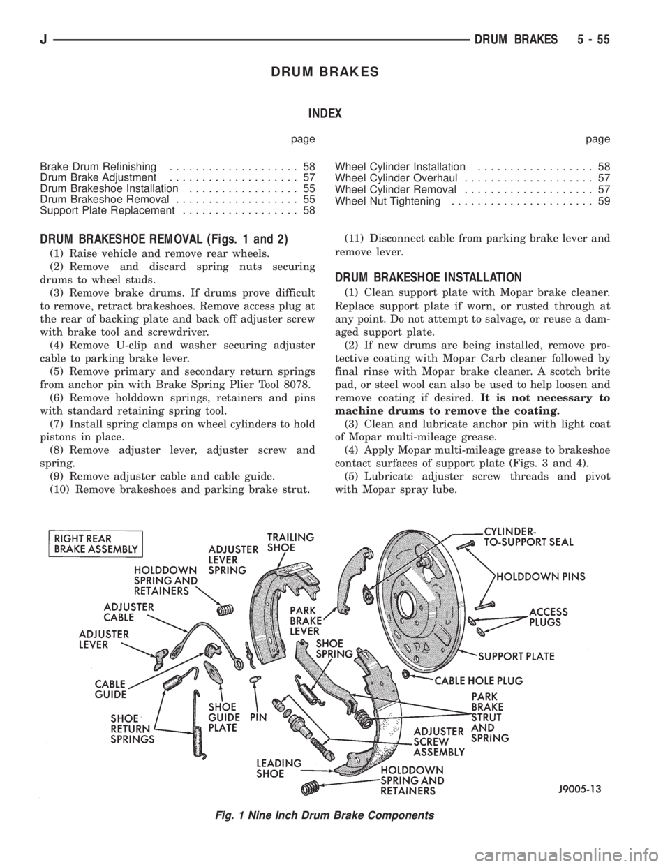
DRUM BRAKESHOE REMOVAL (Figs. 1 and 2)
(1) Raise vehicle and remove rear wheels.
(2) Remove and discard spring nuts securing
drums to wheel studs.
(3) Remove brake drums. If drums prove difficult
to remove, retract brakeshoes. Remove access plug at
the rear of backing plate and back off adjuster screw
with brake tool and screwdriver.
(4) Remove U-clip and washer securing adjuster
cable to parking brake lever.
(5) Remove primary and secondary return springs
from anchor pin with Brake Spring Plier Tool 8078.
(6) Remove holddown springs, retainers and pins
with standard retaining spring tool.
(7) Install spring clamps on wheel cylinders to hold
pistons in place.
(8) Remove adjuster lever, adjuster screw and
spring.
(9) Remove adjuster cable and cable guide.
(10) Remove brakeshoes and parking brake strut.(11) Disconnect cable from parking brake lever and
remove lever.
DRUM BRAKESHOE INSTALLATION
(1) Clean support plate with Mopar brake cleaner.
Replace support plate if worn, or rusted through at
any point. Do not attempt to salvage, or reuse a dam-
aged support plate.
(2) If new drums are being installed, remove pro-
tective coating with Mopar Carb cleaner followed by
final rinse with Mopar brake cleaner. A scotch brite
pad, or steel wool can also be used to help loosen and
remove coating if desired.It is not necessary to
machine drums to remove the coating.
(3) Clean and lubricate anchor pin with light coat
of Mopar multi-mileage grease.
(4) Apply Mopar multi-mileage grease to brakeshoe
contact surfaces of support plate (Figs. 3 and 4).
(5) Lubricate adjuster screw threads and pivot
with Mopar spray lube.
Fig. 1 Nine Inch Drum Brake Components
JDRUM BRAKES 5 - 55
Page 209 of 2158

DRUM BRAKE ADJUSTMENT
Rear drum brakes are equipped with a self adjust-
ing mechanism. Under normal circumstances, the
only time adjustment is required is when the shoes
are replaced, removed for access to other parts, or
when one or both drums are replaced.
The only tool needed for adjustment is a standard
brake gauge.
Adjustment is performed with the brakeshoes in-
stalled on the support plate. Procedure is as follows:
ADJUSTMENT PROCEDURE
(1) Raise and support vehicle rear end and remove
wheels and brake drums.
(2) Verify that left/right automatic adjuster lever
and cable are properly connected.
(3) Insert brake gauge in drum. Expand gauge un-
til gauge inner legs contact drum braking surface.
Then lock gauge in position (Fig. 6).
(4) Reverse gauge and install it on brakeshoes
(Fig. 6). Position gauge legs at shoe centers as
shown. If gauge does not fit (too loose or tight), ad-
just shoes.
(5) Pull shoe adjuster star wheel away from ad-
juster lever.(6) Turn adjuster star wheel (by hand) to expand
or retract brakeshoes. Continue adjustment until
gauge outside legs are light drag-fit on shoes (Fig. 7).
(7) Repeat adjustment at opposite brakeshoe as-
sembly.
(8) Install brake drums and wheels and lower ve-
hicle.
(9) Make final adjustment as follows:
(a) Drive vehicle and make one forward stop fol-
lowed by one reverse stop.
(b) Repeat procedure 8-10 times to actuate self
adjuster components and equalize adjustment.
(c)Bring vehicle to complete standstill at
each stop. Incomplete, rolling stops will NOT
activate adjuster mechanism.
WHEEL CYLINDER REMOVAL
(1) Raise vehicle and remove wheel.
(2) Disconnect brakeline at wheel cylinder.If cyl-
inder brakeline fitting is hard to break loose,
spray generous amount of Mopar Rust Pene-
trant between fitting and line and around fit-
ting threads in wheel cylinder. Note that it may
require a few minutes for penetrant to work.
(3) Remove brakeshoes.
(4) Remove bolts attaching wheel cylinder to sup-
port plate and remove cylinder.
WHEEL CYLINDER OVERHAUL (Figs. 8 and 9)
(1) Remove links.
(2) Remove dust boots.
(3) Remove cups and pistons. Discard cups.
(4) Remove and discard spring and expander.
(5) Remove bleed screw.
(6) Clean cylinder, pistons and links with Mopar
brake cleaner.
(7) Inspect cylinder bore and pistons. Light discol-
oration of bore is acceptable. However, replace cylin-
der if bore and pistons are scored, pitted, or corroded.
Fig. 5 Adjuster Screw Components (9-Inch Brake)
Fig. 6 Adjusting Gauge To Brake Drum
Fig. 7 Adjusting Brakeshoes To Gauge
JDRUM BRAKES 5 - 57
Page 219 of 2158

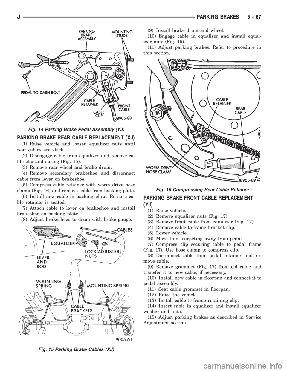
PARKING BRAKE REAR CABLE REPLACEMENT (XJ)
(1) Raise vehicle and loosen equalizer nuts until
rear cables are slack.
(2) Disengage cable from equalizer and remove ca-
ble clip and spring (Fig. 15).
(3) Remove rear wheel and brake drum.
(4) Remove secondary brakeshoe and disconnect
cable from lever on brakeshoe.
(5) Compress cable retainer with worm drive hose
clamp (Fig. 16) and remove cable from backing plate.
(6) Install new cable in backing plate. Be sure ca-
ble retainer is seated.
(7) Attach cable to lever on brakeshoe and install
brakeshoe on backing plate.
(8) Adjust brakeshoes to drum with brake gauge.(9) Install brake drum and wheel.
(10) Engage cable in equalizer and install equal-
izer nuts (Fig. 15).
(11) Adjust parking brakes. Refer to procedure in
this section.
PARKING BRAKE FRONT CABLE REPLACEMENT
(YJ)
(1) Raise vehicle.
(2) Remove equalizer nuts (Fig. 17).
(3) Remove front cable from equalizer (Fig. 17).
(4) Remove cable-to-frame bracket clip.
(5) Lower vehicle.
(6) Move front carpeting away from pedal.
(7) Compress clip securing cable to pedal frame
(Fig. 17). Use hose clamp to compress clip.
(8) Disconnect cable from pedal retainer and re-
move cable.
(9) Remove grommet (Fig. 17) from old cable and
transfer it to new cable, if necessary.
(10) Install new cable in floorpan and connect it to
pedal assembly.
(11) Seat cable grommet in floorpan.
(12) Raise the vehicle.
(13) Install cable-to-frame retaining clip.
(14) Insert cable in equalizer and install equalizer
washer and nuts.
(15) Adjust parking brakes as described in Service
Adjustment section.
Fig. 14 Parking Brake Pedal Assembly (YJ)
Fig. 15 Parking Brake Cables (XJ)
Fig. 16 Compressing Rear Cable Retainer
JPARKING BRAKES 5 - 67
Page 225 of 2158

CLUTCH DIAGNOSIS
INDEX
page page
Clutch Contamination....................... 3
Clutch Cover and Disc Runout................ 3
Clutch Housing Misalignment................. 4
Clutch Misalignment........................ 3Flywheel Runout........................... 3
General Diagnosis Information................ 3
Inspection and Diagnosis Charts............... 4
Installation Methods and Parts Usage........... 4
GENERAL DIAGNOSIS INFORMATION
Unless the cause of a clutch problem is obvious, ac-
curate problem diagnosis will usually require a road
test to confirm a problem. Component inspection will
then be required to determine the actual problem
cause.
During a road test, drive the vehicle at normal
speeds. Shift the transmission through all gear
ranges and observe clutch action. If chatter, grab,
slip, or improper release is experienced, remove and
inspect the clutch components. However, if the prob-
lem is noise or hard shifting, further diagnosis may
be needed as the transmission or another driveline
component may be at fault. Careful observation dur-
ing the test will help narrow the problem area.
CLUTCH CONTAMINATION
Fluid contamination is a frequent cause of clutch
malfunctions. Oil, water, or clutch fluid on the clutch
disc and pressure plate surfaces will cause chatter,
slip and grab.
During inspection, note if any components are con-
taminated with oil, hydraulic fluid, or water/road
splash.
Oil contamination indicates a leak at either the
rear main seal or transmission input shaft. Oil leak-
age produces a residue of oil on the housing interior
and on the clutch cover and flywheel. Heat buildup
caused by slippage between the cover, disc and fly-
wheel, can sometimes bake the oil residue onto the
components. The glaze-like residue ranges in color
from amber to black.
Road splash contamination means dirt/water is en-
tering the clutch housing due to loose bolts, housing
cracks, or through hydraulic line openings. Driving
through deep water puddles can force water/road
splash into the housing through such openings.
Clutch fluid leaks are usually from damaged slave
cylinder push rod seals. This type of leak can only be
confirmed by visual inspection.
CLUTCH MISALIGNMENT
Clutch components must be in proper alignment
with the crankshaft and transmission input shaft.Misalignment caused by excessive runout or warpage
of any clutch component will cause grab, chatter and
improper clutch release.
FLYWHEEL RUNOUT
Check flywheel runout whenever misalignment is
suspected. Flywheel runout should not exceed 0.08
mm (0.003 in.). Measure runout at the outer edge of
the flywheel face with a dial indicator. Mount the in-
dicator on a stud installed in place of one of the fly-
wheel bolts.
Common causes of runout are:
²heat warpage
²improper machining
²incorrect bolt tightening
²improper seating on crankshaft flange shoulder
²foreign material on crankshaft flange
Flywheel machining is not recommended. The fly-
wheel clutch surface is machined to a unique contour
and machining will negate this feature. However, mi-
nor flywheel scoring can be cleaned up by hand with
180 grit emery, or with surface grinding equipment.
Remove only enough material to reduce scoring (ap-
proximately 0.001 - 0.003 in.). Heavy stock removal
isnot recommended.Replace the flywheel if scor-
ing is severe and deeper than 0.076 mm (0.003 in.).
Excessive stock removal can result in flywheel crack-
ing or warpage after installation; it can also weaken
the flywheel and interfere with proper clutch release.
Clean the crankshaft flange before mounting the
flywheel. Dirt and grease on the flange surface may
cock the flywheel causing excessive runout. Use new
bolts when remounting a flywheel and secure the
bolts with Mopar Lock And Seal. Tighten flywheel
bolts to specified torque only. Overtightening can dis-
tort the flywheel hub causing runout.
CLUTCH COVER AND DISC RUNOUT
Check the clutch disc before installation. Axial
(face) runout of anewdisc should not exceed 0.50
mm (0.020 in.). Measure runout about 6 mm (1/4 in.)
from the outer edge of the disc facing. Obtain an-
other disc if runout is excessive.
Check condition of the clutch before installation. A
warped cover or diaphragm spring will cause grab
and incomplete release or engagement. Be careful
JCLUTCH DIAGNOSIS 6 - 3
Page 234 of 2158

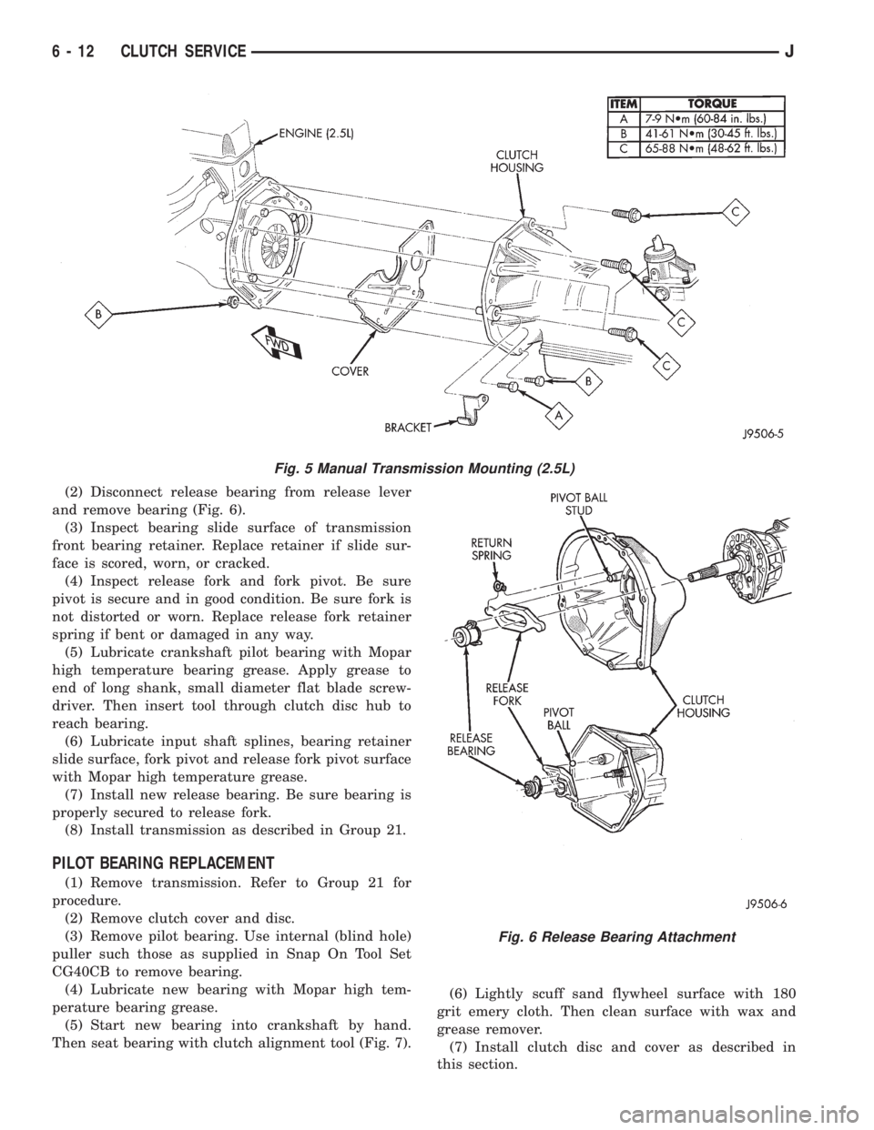
(2) Disconnect release bearing from release lever
and remove bearing (Fig. 6).
(3) Inspect bearing slide surface of transmission
front bearing retainer. Replace retainer if slide sur-
face is scored, worn, or cracked.
(4) Inspect release fork and fork pivot. Be sure
pivot is secure and in good condition. Be sure fork is
not distorted or worn. Replace release fork retainer
spring if bent or damaged in any way.
(5) Lubricate crankshaft pilot bearing with Mopar
high temperature bearing grease. Apply grease to
end of long shank, small diameter flat blade screw-
driver. Then insert tool through clutch disc hub to
reach bearing.
(6) Lubricate input shaft splines, bearing retainer
slide surface, fork pivot and release fork pivot surface
with Mopar high temperature grease.
(7) Install new release bearing. Be sure bearing is
properly secured to release fork.
(8) Install transmission as described in Group 21.
PILOT BEARING REPLACEMENT
(1) Remove transmission. Refer to Group 21 for
procedure.
(2) Remove clutch cover and disc.
(3) Remove pilot bearing. Use internal (blind hole)
puller such those as supplied in Snap On Tool Set
CG40CB to remove bearing.
(4) Lubricate new bearing with Mopar high tem-
perature bearing grease.
(5) Start new bearing into crankshaft by hand.
Then seat bearing with clutch alignment tool (Fig. 7).(6) Lightly scuff sand flywheel surface with 180
grit emery cloth. Then clean surface with wax and
grease remover.
(7) Install clutch disc and cover as described in
this section.
Fig. 5 Manual Transmission Mounting (2.5L)
Fig. 6 Release Bearing Attachment
6 - 12 CLUTCH SERVICEJ
Page 273 of 2158

VISCOUS FAN DRIVE
DESCRIPTION AND OPERATION
Also refer to the previous section on Cooling Sys-
tem Fans.
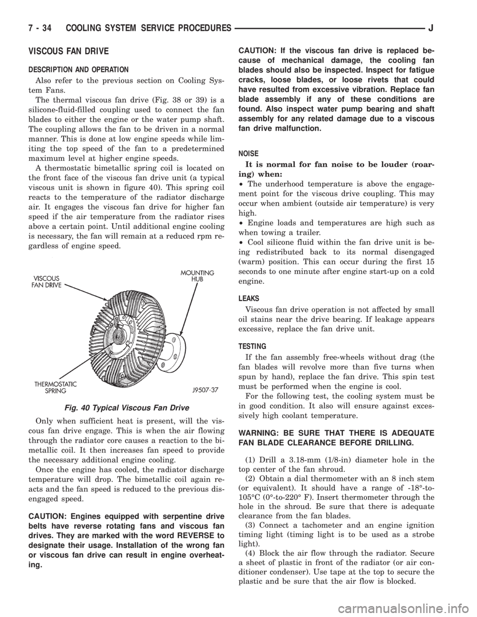
The thermal viscous fan drive (Fig. 38 or 39) is a
silicone-fluid-filled coupling used to connect the fan
blades to either the engine or the water pump shaft.
The coupling allows the fan to be driven in a normal
manner. This is done at low engine speeds while lim-
iting the top speed of the fan to a predetermined
maximum level at higher engine speeds.
A thermostatic bimetallic spring coil is located on
the front face of the viscous fan drive unit (a typical
viscous unit is shown in figure 40). This spring coil
reacts to the temperature of the radiator discharge
air. It engages the viscous fan drive for higher fan
speed if the air temperature from the radiator rises
above a certain point. Until additional engine cooling
is necessary, the fan will remain at a reduced rpm re-
gardless of engine speed.
Only when sufficient heat is present, will the vis-
cous fan drive engage. This is when the air flowing
through the radiator core causes a reaction to the bi-
metallic coil. It then increases fan speed to provide
the necessary additional engine cooling.
Once the engine has cooled, the radiator discharge
temperature will drop. The bimetallic coil again re-
acts and the fan speed is reduced to the previous dis-
engaged speed.
CAUTION: Engines equipped with serpentine drive
belts have reverse rotating fans and viscous fan
drives. They are marked with the word REVERSE to
designate their usage. Installation of the wrong fan
or viscous fan drive can result in engine overheat-
ing.CAUTION: If the viscous fan drive is replaced be-
cause of mechanical damage, the cooling fan
blades should also be inspected. Inspect for fatigue
cracks, loose blades, or loose rivets that could
have resulted from excessive vibration. Replace fan
blade assembly if any of these conditions are
found. Also inspect water pump bearing and shaft
assembly for any related damage due to a viscous
fan drive malfunction.
NOISE
It is normal for fan noise to be louder (roar-
ing) when:
²The underhood temperature is above the engage-
ment point for the viscous drive coupling. This may
occur when ambient (outside air temperature) is very
high.
²Engine loads and temperatures are high such as
when towing a trailer.
²Cool silicone fluid within the fan drive unit is be-
ing redistributed back to its normal disengaged
(warm) position. This can occur during the first 15
seconds to one minute after engine start-up on a cold
engine.
LEAKS
Viscous fan drive operation is not affected by small
oil stains near the drive bearing. If leakage appears
excessive, replace the fan drive unit.
TESTING
If the fan assembly free-wheels without drag (the
fan blades will revolve more than five turns when
spun by hand), replace the fan drive. This spin test
must be performed when the engine is cool.
For the following test, the cooling system must be
in good condition. It also will ensure against exces-
sively high coolant temperature.
WARNING: BE SURE THAT THERE IS ADEQUATE
FAN BLADE CLEARANCE BEFORE DRILLING.
(1) Drill a 3.18-mm (1/8-in) diameter hole in the
top center of the fan shroud.
(2) Obtain a dial thermometer with an 8 inch stem
(or equivalent). It should have a range of -18É-to-
105ÉC (0É-to-220É F). Insert thermometer through the
hole in the shroud. Be sure that there is adequate
clearance from the fan blades.
(3) Connect a tachometer and an engine ignition
timing light (timing light is to be used as a strobe
light).
(4) Block the air flow through the radiator. Secure
a sheet of plastic in front of the radiator (or air con-
ditioner condenser). Use tape at the top to secure the
plastic and be sure that the air flow is blocked.
Fig. 40 Typical Viscous Fan Drive
7 - 34 COOLING SYSTEM SERVICE PROCEDURESJ