1995 JEEP YJ brake
[x] Cancel search: brakePage 1848 of 2158
SHIFT LINKAGE ADJUSTMENT
(1) Shift transfer case into 4L position.
(2) Raise vehicle.
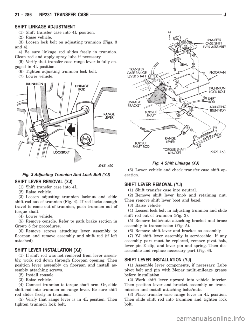
(3) Loosen lock bolt on adjusting trunnion (Figs. 3
and 4).
4) Be sure linkage rod slides freely in trunnion.
Clean rod and apply spray lube if necessary.
(5) Verify that transfer case range lever is fully en-
gaged in 4L position.
(6) Tighten adjusting trunnion lock bolt.
(7) Lower vehicle.
SHIFT LEVER REMOVAL (XJ)
(1) Shift transfer case into 4L.
(2) Raise vehicle.
(3) Loosen adjusting trunnion locknut and slide
shift rod out of trunnion (Fig. 4). If rod lacks enough
travel to come out of trunnion, push trunnion out of
torque shaft.
(4) Lower vehicle.
(5) Remove console. Refer to park brake section in
Group 5 for procedures.
(6) Remove screws attaching lever assembly to
floorpan and remove assembly and shift rod (if left
attached).
SHIFT LEVER INSTALLATION (XJ)
(1) If shift rod was not removed from lever assem-
bly, work rod down through floorpan opening. Then
position lever assembly on floorpan and install as-
sembly attaching screws.
(2) Install console.
(3) Raise vehicle.
(4) Connect trunnion to torque shaft arm. Or, slide
shift rod into trunnion on range lever. Be sure shift
rod slides freely in trunnion.
(5) Verify that range lever is in 4L position. Then
tighten trunnion lock bolt.(6) Lower vehicle and check transfer case shift op-
eration.
SHIFT LEVER REMOVAL (YJ)
(1) Shift transfer case into neutral.
(2) Remove shift lever knob and retaining nut.
Then remove shift lever boot and bezel.
(3) Raise vehicle
(4) Loosen lock bolt in adjusting trunnion and slide
shift rod out of trunnion (Fig. 3).
(5) Remove bolts/nuts attaching bracket and brace
assembly to transmission (Fig. 5).
(6) Remove shift lever and bracket as assembly.
(7) YJ shift lever assembly is serviceable. If any
assembly part must be replaced, remove pivot bolt,
lever pin E-clip, and lever pin and spring. Then dis-
assemble and replace necessary part (Fig. 6).
SHIFT LEVER INSTALLATION (YJ)
(1) Assemble lever components, if necessary. Lube
pivot bolt and pin with Mopar multi-mileage grease
before installation.
(2) Work shift lever upward into vehicle interior.
Then position lever and bracket assembly on trans-
mission and install attaching bolts/nuts.
(3) Place transfer case range lever in 4L position.
Then slide shift rod into trunnion and tighten lock
bolt.
Fig. 3 Adjusting Trunnion And Lock Bolt (YJ)
Fig. 4 Shift Linkage (XJ)
21 - 286 NP231 TRANSFER CASEJ
Page 1871 of 2158
SHIFT LINKAGE ADJUSTMENT
(1) Shift transfer case into 4L position.
(2) Raise vehicle.
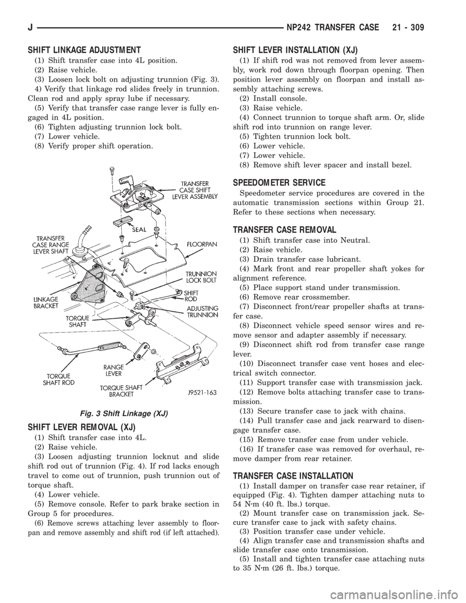
(3) Loosen lock bolt on adjusting trunnion (Fig. 3).
4) Verify that linkage rod slides freely in trunnion.
Clean rod and apply spray lube if necessary.
(5) Verify that transfer case range lever is fully en-
gaged in 4L position.
(6) Tighten adjusting trunnion lock bolt.
(7) Lower vehicle.
(8) Verify proper shift operation.
SHIFT LEVER REMOVAL (XJ)
(1) Shift transfer case into 4L.
(2) Raise vehicle.
(3) Loosen adjusting trunnion locknut and slide
shift rod out of trunnion (Fig. 4). If rod lacks enough
travel to come out of trunnion, push trunnion out of
torque shaft.
(4) Lower vehicle.
(5) Remove console. Refer to park brake section in
Group 5 for procedures.
(6) Remove screws attaching lever assembly to floor-
pan and remove assembly and shift rod (if left attached).
SHIFT LEVER INSTALLATION (XJ)
(1) If shift rod was not removed from lever assem-
bly, work rod down through floorpan opening. Then
position lever assembly on floorpan and install as-
sembly attaching screws.
(2) Install console.
(3) Raise vehicle.
(4) Connect trunnion to torque shaft arm. Or, slide
shift rod into trunnion on range lever.
(5) Tighten trunnion lock bolt.
(6) Lower vehicle.
(7) Lower vehicle.
(8) Remove shift lever spacer and install bezel.
SPEEDOMETER SERVICE
Speedometer service procedures are covered in the
automatic transmission sections within Group 21.
Refer to these sections when necessary.
TRANSFER CASE REMOVAL
(1) Shift transfer case into Neutral.
(2) Raise vehicle.
(3) Drain transfer case lubricant.
(4) Mark front and rear propeller shaft yokes for
alignment reference.
(5) Place support stand under transmission.
(6) Remove rear crossmember.
(7) Disconnect front/rear propeller shafts at trans-
fer case.
(8) Disconnect vehicle speed sensor wires and re-
move sensor and adapter assembly if necessary.
(9) Disconnect shift rod from transfer case range
lever.
(10) Disconnect transfer case vent hoses and elec-
trical switch connector.
(11) Support transfer case with transmission jack.
(12) Remove bolts attaching transfer case to trans-
mission.
(13) Secure transfer case to jack with chains.
(14) Pull transfer case and jack rearward to disen-
gage transfer case.
(15) Remove transfer case from under vehicle.
(16) If transfer case was removed for overhaul, re-
move damper from rear retainer.
TRANSFER CASE INSTALLATION
(1) Install damper on transfer case rear retainer, if
equipped (Fig. 4). Tighten damper attaching nuts to
54 Nzm (40 ft. lbs.) torque.
(2) Mount transfer case on transmission jack. Se-
cure transfer case to jack with safety chains.
(3) Position transfer case under vehicle.
(4) Align transfer case and transmission shafts and
slide transfer case onto transmission.
(5) Install and tighten transfer case attaching nuts
to 35 Nzm (26 ft. lbs.) torque.
Fig. 3 Shift Linkage (XJ)
JNP242 TRANSFER CASE 21 - 309
Page 1903 of 2158
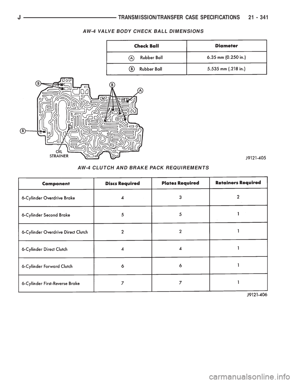
AW-4 VALVE BODY CHECK BALL DIMENSIONS
AW-4 CLUTCH AND BRAKE PACK REQUIREMENTS
JTRANSMISSION/TRANSFER CASE SPECIFICATIONS 21 - 341
Page 1907 of 2158
WHEELS AND TIRES
CONTENTS
page page
SPECIFICATIONS........................ 12
TIRES.................................. 1VEHICLE VIBRATION..................... 10
WHEELS................................ 6
TIRES
INDEX
page page
Cleaning of Tires.......................... 2
General Information........................ 1
Pressure Gauges.......................... 2
Repairing Leaks........................... 3
Replacement Tires......................... 2Rotation................................. 3
Tire Inflation Pressures...................... 2
Tire Noise or Vibration...................... 4
Tire Wear Patterns......................... 4
Tread Wear Indicators....................... 3
GENERAL INFORMATION
Tires are designed for each specific vehicle. They
provide the best overall performance for normal oper-
ation. The ride and handling characteristics match
the vehicle's requirements. With proper care they
will give excellent reliability, traction, skid resis-
tance, and tread life. These tires have specific load
carrying capacities. When correctly inflated, they will
operate properly.
Tires used in cool climates, and with light loads
will have a longer life than tires used in hot climates
with heavy loads. Abrasive road surfaces will acceler-
ate tire wear.
Driving habits have more effect on tire life than
any other factor. Careful drivers will obtain much
greater mileage than careless drivers.
Driving habits that shorten the life of any tire;
²Rapid acceleration and deceleration
²Severe application of brakes
²High-speed driving
²Taking turns at excessive speeds
²Striking curbs and other obstacles
It is very important to follow the tire rotation in-
terval
IDENTIFICATION
Tire type, size, aspect ratio and speed rating are
encoded in the letters and numbers imprinted on the
side wall of the tire. Refer to the chart to decipher
the tire identification code (Fig. 1).Performance tires will have a speed rating letter
after the aspect ratio number. The speed rating is not
always printed on the tire sidewall. The letterSin-
dicates that the tire is speed rated up to 112 mph.
²Qup to 100 mph
²Tup to 118 mph
²Uup to 124 mph
²Hup to 130 mph
²Vup to 149 mph
²Zmore than 149 mph (consult the tire manufac-
turer for the specific speed rating)
An All Season type tire will have eitherM+S,M
&SorMÐS(indicating mud and snow traction) im-
printed on the side wall.
RADIAL-PLY TIRES
Radial-ply tires improve handling, tread life, ride
quality and decrease rolling resistance.
Radial-ply tires must always be used in sets of
four. Under no circumstances should they be used on
the front only. They may be mixed with temporary
spare tires when necessary, but reduced speeds are
recommended.
Radial-ply tires have the same load-carrying capac-
ity as other types of tires of the same size. They use
the same recommended inflation pressures.
SPARE TIRE (TEMPORARY)
The compact spare tire is designed for emergency
use only. The original tire should be repaired and re-
installed at the first opportunity. Refer to Owner's
Manual for complete details.
JWHEELS AND TIRES 22 - 1
Page 1915 of 2158
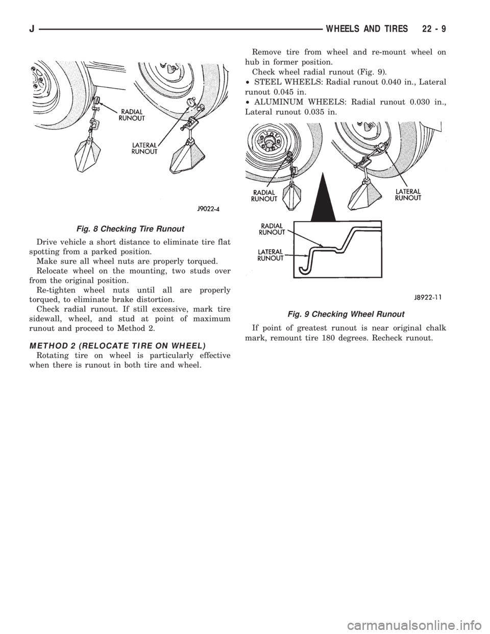
Drive vehicle a short distance to eliminate tire flat
spotting from a parked position.
Make sure all wheel nuts are properly torqued.
Relocate wheel on the mounting, two studs over
from the original position.
Re-tighten wheel nuts until all are properly
torqued, to eliminate brake distortion.
Check radial runout. If still excessive, mark tire
sidewall, wheel, and stud at point of maximum
runout and proceed to Method 2.
METHOD 2 (RELOCATE TIRE ON WHEEL)
Rotating tire on wheel is particularly effective
when there is runout in both tire and wheel.Remove tire from wheel and re-mount wheel on
hub in former position.
Check wheel radial runout (Fig. 9).
²STEEL WHEELS: Radial runout 0.040 in., Lateral
runout 0.045 in.
²ALUMINUM WHEELS: Radial runout 0.030 in.,
Lateral runout 0.035 in.
If point of greatest runout is near original chalk
mark, remount tire 180 degrees. Recheck runout.
Fig. 8 Checking Tire Runout
Fig. 9 Checking Wheel Runout
JWHEELS AND TIRES 22 - 9
Page 1916 of 2158
VEHICLE VIBRATION
Vehicle vibration can be caused by:
²Tire/wheel unbalance or excessive runout
²Defective tires with extreme tread wear
²Nylon overlay flat spots (performance tires only)
²Incorrect wheel bearing adjustment (if applicable)
²Loose or worn suspension/steering components
²Certain tire tread patterns
²Incorrect drive shaft angles or excessive drive
shaft/yoke runout
²Defective or worn U-joints
²Excessive brake rotor or drum runout
²Loose engine or transmission supports/mounts
²And by engine operated accessories
Refer to the appropriate Groups in this man-
ual for additional information.
VIBRATION TYPES
There are two types of vehicle vibration:
²Mechanical
²Audible.
Mechanical vehicle vibration can be felt through
the seats, floor pan and/or steering wheel.
Audible vehicle vibration is heard above normal
background noise. The sound can be a droning or
drumming noise.
Vibrations are sensitive to change in engine torque,
vehicle speed or engine speed.
ENGINE TORQUE SENSITIVE VIBRATION
This vibration can be increased or decreased by:
²Accelerating
²Decelerating
²Coasting
²Maintaining a constant vehicle speed
VEHICLE SPEED SENSITIVE VIBRATION
This vibration condition always occurs at the same
vehicle speed regardless of the engine torque or en-
gine speed.
ENGINE SPEED (RPM) SENSITIVE VIBRATION
This vibration occurs at varying engine speeds. It
can be isolated by increasing or decreasing the en-
gine speed with the transmission in NEUTRAL posi-
tion.
VIBRATION DIAGNOSIS
A vibration diagnosis should always begin with a
10 mile (16 km) trip (to warm the vehicle and tires).
Then a road test to identify the vibration. Corrective
action should not be attempted until the vibration
type has been identified via a road test.
During the road test, drive the vehicle on a smooth
surface. If vibration exists, note and record the fol-
lowing information:²Identify the vehicle speed range when the vibra-
tion occurs
²Identify the type of vibration
²Identify the vibration sensitivity
²Determine if the vibration is affected by changes
in vehicle speed, engine speed and engine torque.
When the vibration has been identified, refer to the
Vibration Diagnosis chart for causes. Consider cor-
recting only those causes coded in the chart that are
related to the vibration condition.
Refer to the following cause codes and descriptions
for explanations when referring to the chart.
TRRÐTire and Wheel Radial Runout:Vehicle
speed sensitive, mechanical vibration. The runout
will not cause vibration below 20 mph (32 km/h).
WHÐWheel Hop:Vehicle speed sensitive, me-
chanical vibration. The wheel hop generates rapid
up-down movement in the steering wheel. The vibra-
tion is most noticeable in the 20 - 40 mph (32 - 64
km/h) range. The wheel hop will not cause vibration
below 20 mph (32 km/h). Wheel hop is caused by a
tire/wheel that has a radial runout of more than
0.045 of-an-inch (1.14 mm). If wheel runout is accept-
able and combined runout cannot be reduced by re-
positioning the tire on wheel, replace tire.
TBÐTire/Wheel Balance:Vehicle speed sensitive,
mechanical vibration. Static tire/wheel unbalance
will not cause vibration below 30 mph (46 km/h). Dy-
namic tire/wheel unbalance will not cause vibration
below 40 mph (64 km/h).
TLRÐTire/Wheel Lateral runout:Vehicle speed
sensitive, mechanical vibration. The runout will not
cause vibration below 50 - 55 mph (80 - 88 km/h). Ex-
cessive lateral runout will also cause front-end
shimmy.
TWÐTire Wear:Vehicle speed sensitive, audible
vibration. Abnormal tire wear causes small vibration
in the 30 - 55 mph (88 km/h) range. This will pro-
duce a whine noise at high speed. The whine will
change to a growl noise when the speed is reduced.
WÐTire Waddle:Vehicle speed sensitive, mechan-
ical vibration. Irregular tire uniformity can cause
side-to-side motion during speeds up to 15 mph (24
km/h). If the motion is excessive, identify the defec-
tive tire and replace it.
UAJÐUniversal Joint (Drive Shaft) Angles:
Torque/vehicle speed sensitive, mechanical/audible vi-
bration. Incorrect drive shaft angles cause mechani-
cal vibration below 20 mph (32 km/h) and in the 70
mph (112 km/h) range. The incorrect angles can also
produce an audible vibration in the 20 - 50 mph (32 -
80 km/h) range. Caster adjustment could be required
to correct the angles.
UJÐUniversal Joints:Engine torque/vehicle
speed sensitive, mechanical/audible vibration. If the
22 - 10 WHEELS AND TIRESJ
Page 1995 of 2158
TRAILER HITCH
TRAILER HITCHÐXJ
CLASS III HITCH
A class III weight-distributing/equalizer type hitch
can be used to tow a trailer:
²Having a maximum gross weight of 5,000 lbs/2250
kg.
²Having a maximum tongue weight of 750 lbs/332
kg).
The following vehicle basic equipment is required
for class III trailer towing:
²P205/75R15 or larger tires.
²Full size spare tire.
²Trailer sway control.
²Trailer tow wire harness and connector.
²Heavy duty turn signal flasher element.
²Heavy duty axle (with synthetic lubricant).
²Heavy duty cooling system.
²Heavy duty generator/battery.
²Auxiliary automatic transmission fluid cooler.
²I-6, 4.0L engine.
Wide-angle type door mirrors are recommended but
not required.
WIRE HARNESS CONNECTORS
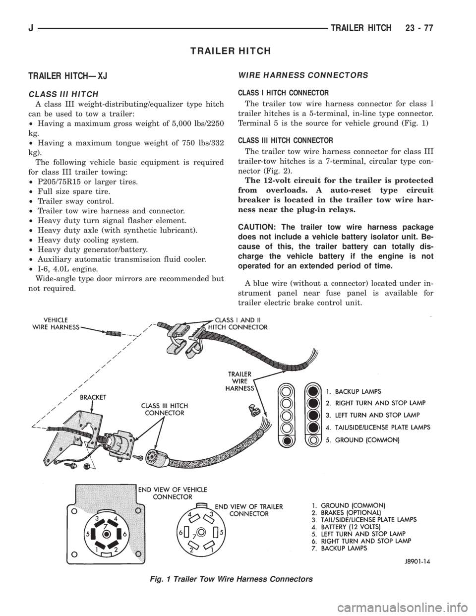
CLASS I HITCH CONNECTOR
The trailer tow wire harness connector for class I
trailer hitches is a 5-terminal, in-line type connector.
Terminal 5 is the source for vehicle ground (Fig. 1)
CLASS III HITCH CONNECTOR
The trailer tow wire harness connector for class III
trailer-tow hitches is a 7-terminal, circular type con-
nector (Fig. 2).
The 12-volt circuit for the trailer is protected
from overloads. A auto-reset type circuit
breaker is located in the trailer tow wire har-
ness near the plug-in relays.
CAUTION: The trailer tow wire harness package
does not include a vehicle battery isolator unit. Be-
cause of this, the trailer battery can totally dis-
charge the vehicle battery if the engine is not
operated for an extended period of time.
A blue wire (without a connector) located under in-
strument panel near fuse panel is available for
trailer electric brake control unit.
Fig. 1 Trailer Tow Wire Harness Connectors
JTRAILER HITCH 23 - 77
Page 1998 of 2158
INTERIOR COMPONENTS
INDEX
page page
Assist HandleÐXJ........................ 89
B/C-Pillar and Liftgate Pillar Trim CoversÐXJ.... 88
Bucket Seat Cushion and CoverÐXJ........... 81
Bucket Seat PlatformÐXJ................... 82
Bucket Seatback Cover and FrameÐXJ........ 81
Cargo BarrierÐXJ........................ 101
Cargo LampÐXJ......................... 94
Carpets and Floor MatsÐXJ................. 99
Dome LampÐXJ......................... 93
Front Bucket SeatsÐXJ.................... 81
Front Carpet/MatÐXJ...................... 99
Front Inner Scuff Plate/Cowl Side Trim PanelÐXJ . 86
Front Shoulder Belt/BuckleÐXJ............... 90
Full Floor ConsoleÐXJ..................... 95
HeadlinerÐXJ............................ 92
I/P Ash Receiver Tray LampÐXJ.............. 80
Instrument Cluster BezelÐXJ................ 80
Interior Trim Panels and Scuff PlatesÐXJ....... 84
Jack StorageÐXJ......................... 97
Keyless Entry ReceiverÐXJ................. 93Mini-Console with Floor ShiftÐXJ............. 94
Mini-Floor ConsoleÐXJ..................... 94
Outer Scuff PlatesÐXJ..................... 89
Overhead ConsoleÐXJ..................... 93
Parking Brake Handle CoverÐXJ............. 94
Quarter and Wheelhouse Trim PanelsÐXJ...... 87
Quarter Trim Panel ExtensionÐXJ............. 87
Rear Carpet/MatÐXJ..................... 100
Rear Seat Cushion CoverÐXJ............... 82
Rear Seat CushionÐXJ.................... 82
Rear Seatback CoverÐXJ................... 84
Rear Seatback Latch Striker and BumperÐXJ.... 84
Rear SeatbackÐXJ........................ 83
Rear Shoulder/Lap Belt/BuckleÐXJ............ 91
Sound BarÐXJ........................... 94
Spare Tire/Wheel Holddown and Floor
BracketsÐXJ........................... 98
SunvisorsÐXJ........................... 93
Windshield Side MoldingÐXJ................ 86
INSTRUMENT CLUSTER BEZELÐXJ
REMOVAL
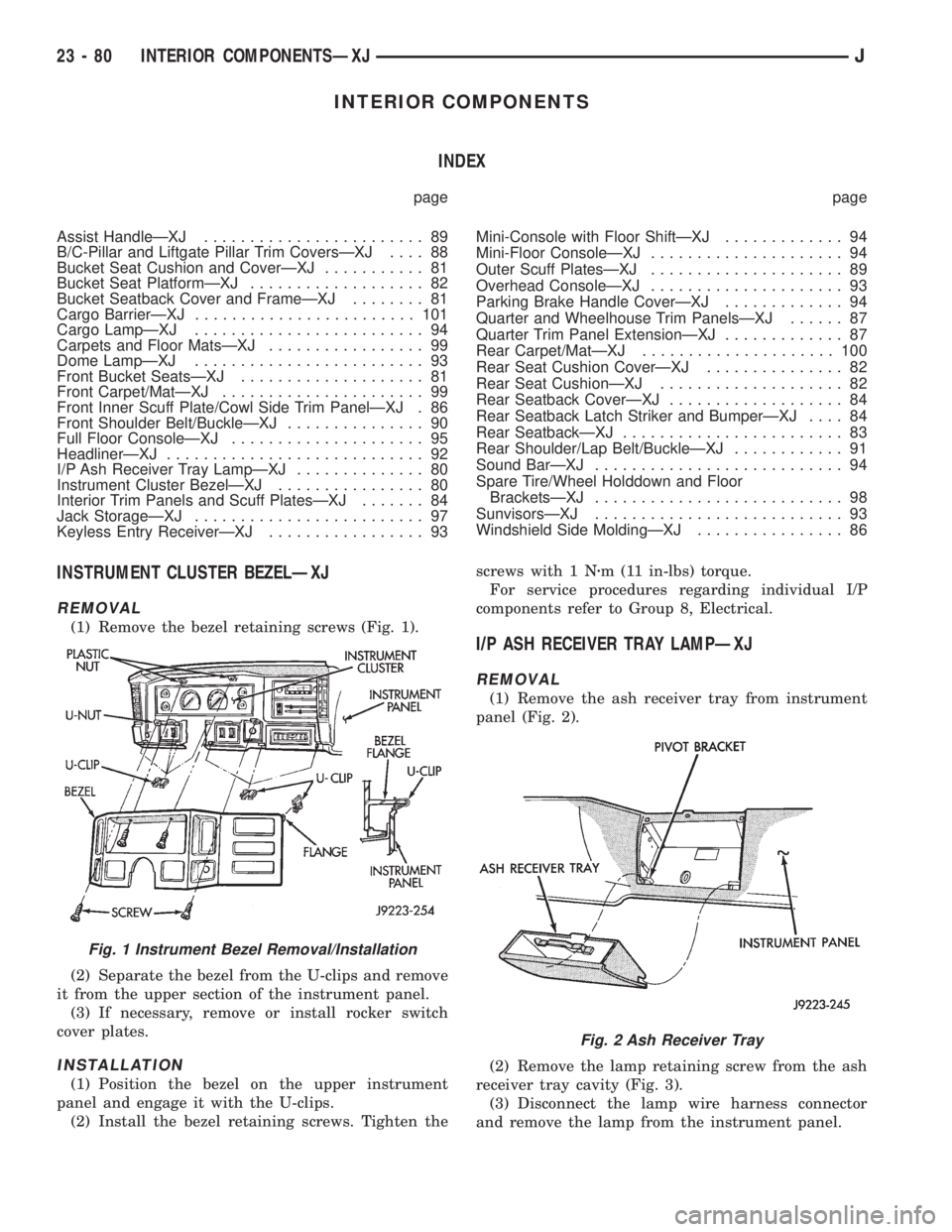
(1) Remove the bezel retaining screws (Fig. 1).
(2) Separate the bezel from the U-clips and remove
it from the upper section of the instrument panel.
(3) If necessary, remove or install rocker switch
cover plates.
INSTALLATION
(1) Position the bezel on the upper instrument
panel and engage it with the U-clips.
(2) Install the bezel retaining screws. Tighten thescrews with 1 Nzm (11 in-lbs) torque.
For service procedures regarding individual I/P
components refer to Group 8, Electrical.
I/P ASH RECEIVER TRAY LAMPÐXJ
REMOVAL
(1) Remove the ash receiver tray from instrument
panel (Fig. 2).
(2) Remove the lamp retaining screw from the ash
receiver tray cavity (Fig. 3).
(3) Disconnect the lamp wire harness connector
and remove the lamp from the instrument panel.
Fig. 1 Instrument Bezel Removal/Installation
Fig. 2 Ash Receiver Tray
23 - 80 INTERIOR COMPONENTSÐXJJ