1995 JEEP YJ trailer
[x] Cancel search: trailerPage 809 of 2158

SPLICE LOCATIONS
GENERAL INFORMATION
This section provides illustrations identifying the
general location of the splices in this vehicle. A splice
index is provided. Use the wiring diagrams in each
section for splice number identification. Refer to the
index for the proper splice number.
SPLICE LOCATIONS
Splice
NumberLocations Fig.
S101 Near Generator T/O..................4
S102 Near Bulkhead T/O...................2
S103 Near Bulkhead T/O...................2
S104 Near Bulkhead T/O...................2
S105 Near Bulkhead T/O...................2
S106 Near Bulkhead T/O...................1
S107 Near Wiper Motor T/O................1
S108 Near Wiper Motor T/O................1
S109 Near Wiper Motor T/O................1
S110 Center of Dash Panel Near Grommet.......1
S111 Near T/O for ABS Diode...............7
S112 Near T/O for Map Sensor..............1
S113 Near T/O for Injector #5 and #6..........4
S114 Near T/O for Injector #5 and #6..........4
S115 Near T/O for Injector #5 and #6..........4
S116 Near T/O for Injector #5 and #6..........4
S117 Near T/O for Map Sensor..............1
S118 Near T/O for Map Sensor..............1
S119 Near Distributor T/O..................1
S120 Between Distributor T/O and Underhood
Lamp T/O.......................1
S121 Between Distributor T/O and Underhood
Lamp T/O.......................1
S122 Between Distributor T/O and Underhood
Lamp T/O.......................1
S123 RT Side of Cowl Panel................1
S124 RT Side of Cowl Panel................1
S125 Near T/O for PDC...................1
S126 Near T/O for Oil Pressure Switch..........5
S127 Near Generator T/O..................5
S128 LT Side of Grille Panel................3
S129 LT Side of Grille Panel................3
S130 Center of Grille Panel.................3
S201 Near Body Harness Connector T/O.........6
S202 Near Body Harness Connector T/O.........6
S203 Near Body Harness Connector T/O.........6
S204 Near Relay Center...................6
S205 Near T/O for Headlamp Switch...........6Splice
NumberLocations Fig.
S206 Near T/O for Telltale..................6
S207 Near T/O for Cluster..................6
S208 Near T/O for Cluster..................6
S209 Right Side of Cluster.................6
S210 Right Side of Cluster.................6
S211 Near Instrument Panel Ground T/O........6
S212 Near Wiper Switch T/O................6
S213 Near Antenna T/O...................7
S214 Near Blower Resistor T/O..............7
S215 Right Side of Instrument Panel...........7
S301 In Left Rear Door T/O.................8
S302 Near Left C-Pillar....................8
S303 Near Left C-Pillar....................8
S304 Near Left C-Pillar....................8
S305 Near Left C-Pillar....................8
S306 Near Left C-Pillar....................8
S307 Left Rear Wheel Well................10
S308 Left Rear Wheel Well................10
S309 Near Left Rear Door T/O...............8
S310 Near Left Rear Door T/O...............8
S311 Left Side of Floor Tunnel...............9
S312 Top of Floor Tunnel..................9
S313 In Power Mirror Switch T/O.............9
S314 Right A- Pillar.....................11
S315 Near RT Vanity Mirror T/O.............11
S316 Near RT Vanity Mirror T/O.............11
S317 In Trailer Tow Harness Near Grommet......14
S318 In Trailer Tow Harness Near Grommet......14
S319 In Liftgate.......................13
S320 Right A-Pillar.....................11
S321 In Left Front Door..................12
S401 In Left Rear Tail Lamp..........Not Shown
S402 In Right Rear Tail Lamp.........Not Shown
S403 In Left Rear Tail Lamp..........Not Shown
S404 In Right Rear Tail Lamp.........Not Shown
J8W-95 SPLICE LOCATIONSÐXJ VEHICLES 8W - 95 - 1
Page 818 of 2158
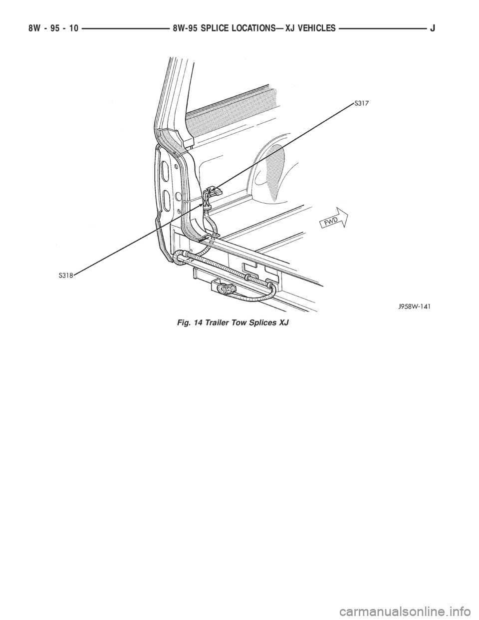
Fig. 14 Trailer Tow Splices XJ
8W - 95 - 10 8W-95 SPLICE LOCATIONSÐXJ VEHICLESJ
Page 819 of 2158

WIRING DIAGRAMS
CONTENTS
page page
8W-01 GENERAL INFORMATIONÐWIRING
DIAGRAMS...................... 8W-01-1
8W-10 FUSE/FUSE BLOCK........... 8W-10-1
8W-11 POWER DISTRIBUTION........ 8W-11-1
8W-15 GROUND DISTRIBUTION....... 8W-15-1
8W-20 CHARGING SYSTEM.......... 8W-20-1
8W-21 STARTING SYSTEM........... 8W-21-1
8W-30 FUEL/IGNITION.............. 8W-30-1
8W-31 TRANSMISSION CONTROLS.... 8W-31-1
8W-32 ANTI-LOCK BRAKES........... 8W-32-1
8W-33 VEHICLE SPEED CONTROL..... 8W-33-1
8W-40 INSTRUMENT CLUSTER....... 8W-40-1
8W-41 HORN/CIGAR LIGHTER........ 8W-41-1
8W-42 AIR CONDITIONING/HEATER.... 8W-42-1
8W-44 INTERIOR LIGHTING.......... 8W-44-1
8W-47 AUDIO SYSTEM.............. 8W-47-18W-48 HEATED REAR WINDOW....... 8W-48-1
8W-49 OVERHEAD CONSOLE.......... 8W-49-1
8W-50 FRONT LIGHTING............ 8W-50-1
8W-51 REAR LIGHTING............. 8W-51-1
8W-52 TURN SIGNALS.............. 8W-52-1
8W-53 WIPERS.................... 8W-53-1
8W-54 TRAILER TOW................ 8W-54-1
8W-60 POWER WINDOWS............ 8W-60-1
8W-61 POWER DOOR LOCKS......... 8W-61-1
8W-62 POWER MIRRORS............ 8W-62-1
8W-63 POWER SEAT................ 8W-63-1
8W-70 SPLICE INFORMATION........ 8W-70-1
8W-80 CONNECTOR PIN OUTS....... 8W-80-1
8W-90 CONNECTOR LOCATIONS...... 8W-90-1
8W-95 SPLICE LOCATIONS........... 8W-95-1
HOW TO USE THIS GROUP
The purpose of this group is to show the electrical
circuits in a clear, simple fashion and to make trou-
bleshooting easier. Components that work together
are shown together. All electrical components used in
a specific system are shown on one diagram. The feed
for a system is shown at the top of the page. All
wires, connectors, splices, and components are shown
in the flow of current to the bottom of the page. Wir-
ing which is not part of the circuit represented is ref-
erenced to another page/section, where the complete
circuit is shown. In addition, all switches, compo-
nents, and modules are shown in theat rest posi-
tion with the doors closed and the key removed
from the ignition.
If a component is part of several different circuits,
it is shown in the diagram for each. For example, the
headlamp switch is the main part of the exterior
lighting, but it also affects the interior lighting and
the chime warning system.
It is important to realize that no attempt is
made on the diagrams to represent components
and wiring as they appear on the vehicle. For
example, a short piece of wire is treated the
same as a long one. In addition, switches and
other components are shown as simply as pos-
sible, with regard to function only.
The wiring diagram show circuits for all wheel-
bases. If there is a difference in systems or compo-
nents between wheel-bases, an identifier is placed
next to the component.
SECTION IDENTIFICATION
Sections in Group 8W are organized by sub-sys-
tems. The sections contain circuit operation descrip-
tions, helpful information, and system diagrams. The
intention is to organize information by system, con-
sistently from year to year.
CONNECTOR LOCATIONS
Section 8W-90 contains Connector Location illus-
trations. The illustrations contain the connector
number and component identification. Connector Lo-
cation charts in Section 8W-90 reference the illustra-
tion number for components and connectors.
Section 8W-80 shows each connector and the cir-
cuits involved with that connector. The connectors
are identified using the number on the Diagram
pages.
SPLICE LOCATIONS
Splice Location charts in Section 8W-70 show the
entire splice, and provide references to other sections
the splice serves.
Section 8W-95 contains illustrations that show the
general location of the splices in each harness. The
illustrations show the splice by number, and provide
a written location.
JWIRING DIAGRAMSÐXJ-RHD 8W - 1 - 1
Page 965 of 2158
TRAILER TOW
TRAILER TOW
The factory installed trailer tow system in this ve-
hicle uses three relays and a circuit breaker along
with the trailer tow wiring connector located below
the rear bumper.
Battery voltage for the trailer tow circuit breaker
and relays is supplied on circuit A11. This circuit is
HOT at all times and connects to the power accessory
tap in the fuse block. An in line 10 amp circuit pro-
tected breaker protects circuit A11 and the trailer
tow circuits. The trailer tow circuit breaker is located
in the left rear quarter panel.
STOP LAMP RELAY
Power for the coil side of the stop lamp relay is
supplied by circuit L50. This circuit connects to the
stop lamps. Ground for the coil side is supplied on
circuit Z1.
When the operator depresses the brake pedal, volt-
age flows through the coil of the relay to ground
causing the contacts in the relay to close connecting
circuits A11 and 95.
Circuit 95 connects to the left and right turn signal
relays. Voltage flows through the closed contacts in
the relays to the trailer tow connector.
RIGHT TURN RELAY
Power for the coil side of the right turn relay is
supplied by circuit L60. This circuit connects to the
right side turn signal lamps. Ground for the coil side
of the relay is supplied on circuit Z1.
When the operator turns the right turn signal ON,
power flows through the coil in the relay to ground
causing the contacts in the relay to switch from there
normally CLOSED position to connect circuits 94 and
L60.
Circuit 94 is the feed for the contact side of the re-
lay. Circuit L60 connects from the relay to the trailer
tow connector.
Circuit 94 is fed power through the normally
CLOSED side of the stop lamp relay and circuit A11.
The A11 circuit is HOT at all times and protected by
a 10 amp circuit breaker located in the left rear
quarter panel.
LEFT TURN RELAY
Power for the coil side of the left turn relay is sup-
plied by circuit L61. This circuit connects to the left
side turn signal lamps. Ground for the coil side of the
relay is supplied on circuit Z1.
When the operator turns the left turn signal ON,
power flows through the coil in the relay to ground
causing the contacts in the relay to switch from there
normally CLOSED position to connect circuits 94 and
L61.
Circuit 94 is the feed for the contact side of the re-
lay. Circuit L61 connects from the relay to the trailer
tow connector.
Circuit 94 is fed power through the normally
CLOSED side of the stop lamp relay and circuit A11.
The A11 circuit is HOT at all times and protected by
a 10 amp circuit breaker located in the right rear
quarter panel.
HELPFUL INFORMATION
²Check the In-Line circuit breaker
DIAGRAM INDEX
Component Page
Circuit Breaker (In-Line)....................8W-54-4
Electric Brake Provision....................8W-54-2
Fuse 1 (Fuse Block).......................8W-54-4
Fuse 3 (PDC)...........................8W-54-4
Left Turn Signal Relay.....................8W-54-3
Left Back-Up Lamp.......................8W-54-2
Left Side Marker Lamp.....................8W-54-2
Left Tail/Stop Lamp.......................8W-54-2
Left Turn Signal Lamp.....................8W-54-2
Right Turn Signal Relay....................8W-54-3
Stop Lamp Relay.........................8W-54-3
Trailer Tow Connector......................8W-54-2
J8W-54 TRAILER TOWÐXJ-RHD 8W - 54 - 1
Page 1082 of 2158
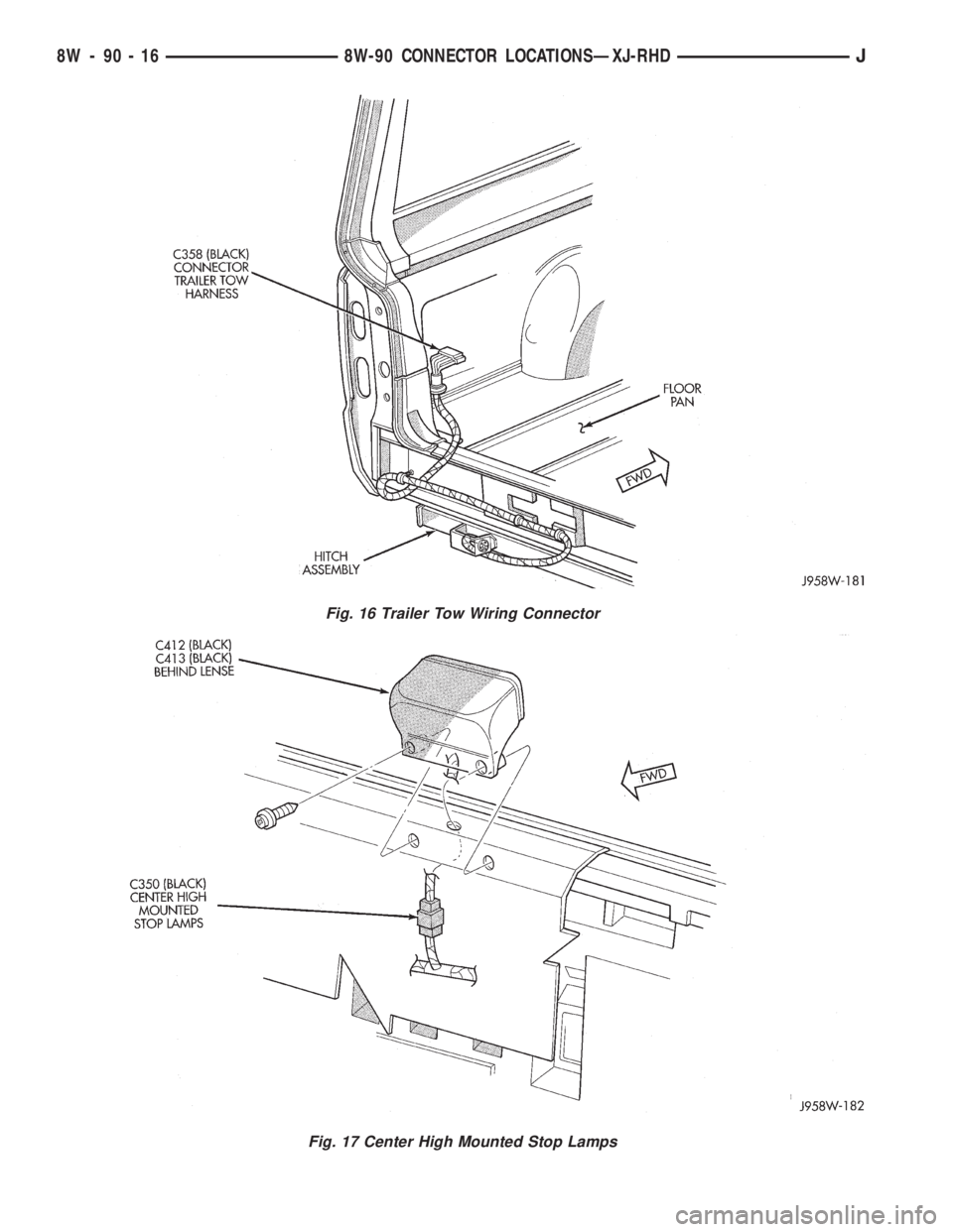
Fig. 16 Trailer Tow Wiring Connector
Fig. 17 Center High Mounted Stop Lamps
8W - 90 - 16 8W-90 CONNECTOR LOCATIONSÐXJ-RHDJ
Page 1086 of 2158
Splice
NumberLocations Fig.
S305......InT/OforFuel Tank Module............9
S306......OnLeft Rear Wheel Well..............9
S307......Before T/O for Right Rear Door Switch.....9
S308......After T/O for Left Front Door Harness
Connectors......................7
S309......After T/O for Left Front Door Harness
Connectors......................7
S310......After T/O for Left Front Door Harness
Connectors......................7
S311......InT/OforElectric Mirror Switch.........7
S312......After Right Front Door Grommet, Before
Power Mirror T/O.................8Splice
NumberLocations Fig.
S313......InLiftgate.......................12
S314......Left Rear Quarter Panel, Near Trailer
Tow Harness Connector.............11
S315......Left Rear Quarter Panel, Near Trailer
Tow Harness Connector.............11
S316......Behind Left Front of Roof Liner.........10
S401......InLeft Tail Lamp Harness.......Not Shown
S402......InRight Tail Lamp Harness......Not Shown
S403......InLeft Tail Lamp Harness.......Not Shown
S404......InRight Tail Lamp Harness......Not Shown
8W - 95 - 2 8W-95 SPLICE LOCATIONSÐXJ-RHDJ
Page 1093 of 2158
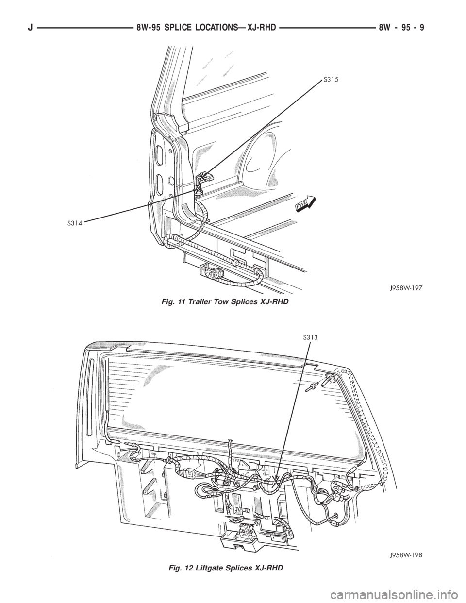
Fig. 11 Trailer Tow Splices XJ-RHD
Fig. 12 Liftgate Splices XJ-RHD
J8W-95 SPLICE LOCATIONSÐXJ-RHD 8W - 95 - 9
Page 1388 of 2158
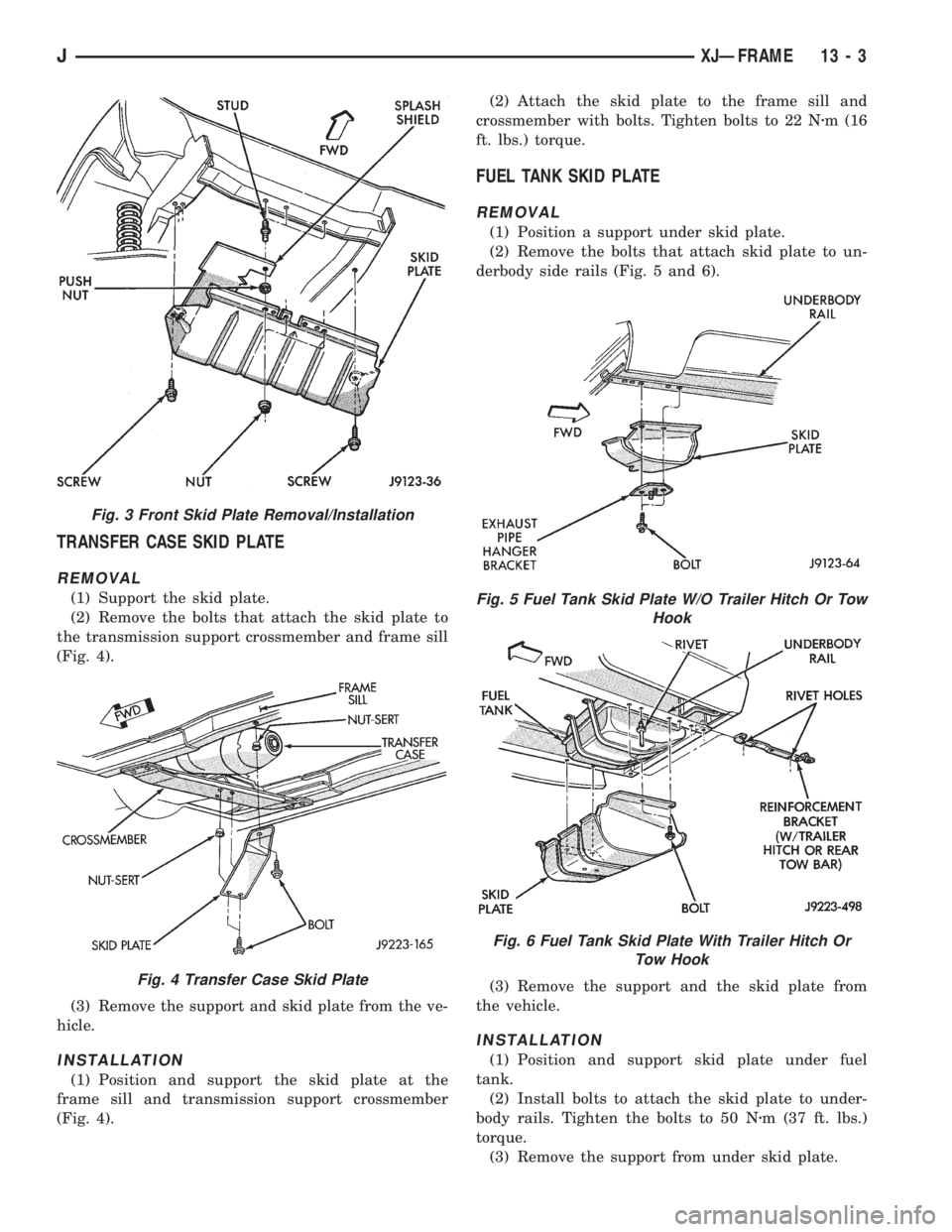
TRANSFER CASE SKID PLATE
REMOVAL
(1) Support the skid plate.
(2) Remove the bolts that attach the skid plate to
the transmission support crossmember and frame sill
(Fig. 4).
(3) Remove the support and skid plate from the ve-
hicle.
INSTALLATION
(1) Position and support the skid plate at the
frame sill and transmission support crossmember
(Fig. 4).(2) Attach the skid plate to the frame sill and
crossmember with bolts. Tighten bolts to 22 Nzm (16
ft. lbs.) torque.
FUEL TANK SKID PLATE
REMOVAL
(1) Position a support under skid plate.
(2) Remove the bolts that attach skid plate to un-
derbody side rails (Fig. 5 and 6).
(3) Remove the support and the skid plate from
the vehicle.
INSTALLATION
(1) Position and support skid plate under fuel
tank.
(2) Install bolts to attach the skid plate to under-
body rails. Tighten the bolts to 50 Nzm (37 ft. lbs.)
torque.
(3) Remove the support from under skid plate.
Fig. 3 Front Skid Plate Removal/Installation
Fig. 4 Transfer Case Skid Plate
Fig. 5 Fuel Tank Skid Plate W/O Trailer Hitch Or Tow
Hook
Fig. 6 Fuel Tank Skid Plate With Trailer Hitch Or
Tow Hook
JXJÐFRAME 13 - 3