1995 JEEP YJ stop start
[x] Cancel search: stop startPage 609 of 2158

TRANSMISSION CONTROLS
UPSHIFT LAMP
On vehicles equipped with a manual transmission,
the PCM grounds the up-shift lamp on circuit K54.
Circuit K54 connects to cavity 54 of the PCM.
FOUR-WHEEL DRIVE (4WD) SWITCH
When the 4WD switch closes, circuit Z1 provides
ground for the 4WD indicator lamp in the instrument
cluster. Circuit F87 connects to the instrument clus-
ter and supplies battery voltage to the 4WD indicator
lamp. Circuit 107 connects the indicator lamp to the
4WD switch. Circuit 106 connects the lamp to the in-
strument cluster and circuit F87.
TRANSMISSION CONTROL MODULEÐ4.0L
ENGINE ONLY
Vehicles equipped with the 4.0L engine have elec-
tronically controlled solenoids in the automatic trans-
mission valve body.
The Transmission Control Module (TCM) receives
inputs from the Throttle Position Sensor (TPS) on
circuit K22 and the stop lamp switch on circuit K29.
Circuit K4 connects to the TCM to provide ground for
the TPS signal. The TCM receives the transmission
output speed sensor signal on circuit T505. Circuit
A14 from fuse 2 in the Power Distribution Center
supplies battery voltage to the TCM. Circuit Z12 pro-
vides ground for the TCM.
The TCM powers the S1 solenoid on circuit T510,
the S2 solenoid on circuit T509, and the S3 solenoid
on circuit T508. Circuit Z12 provides ground for the
S1, S2, and S3 solenoids.
TORQUE CONVERTER CLUTCH (TCC) SOLENOID
AND RELAYÐ2.5L ENGINE ONLY
The TCC solenoid is only used on 2.5L engines
with the three-speed automatic transmissions. The
Powertrain Control Module (PCM) operates the TCC
solenoid by energizing the TCC relay.
Circuit T17 from fuse 12 in the Power Distribution
Center (PDC) supplies voltage to the coil and contact
sides of the TCC relay. When the PCM provides a
ground path on circuit K54 for the coil side of the re-
lay, the relay contacts close.
When the relay contacts close, they connect circuit
T17 with circuit T22. Circuit T22 supplies battery
voltage to the case grounded TCC solenoid. Circuit
K54 connects to PCM cavity 54.
HELPFUL INFORMATION
²In the RUN or START position, the ignition switch
connects circuit A1 from fuse 6 in the PDC to circuit
A21.
DIAGRAM INDEX
Component Page
4-WD Indicator Lamp......................8W-31-4
4-WD Indicator Switch.....................8W-31-4
Back-Up Lamp Switch.....................8W-31-3
Fuse 2 (PDC)...........................8W-31-4
Fuse 6 (PDC).........................8W-31-2, 3
Fuse 11 (PDC)..........................8W-31-3
Fuse 12 (PDC)..........................8W-31-2
Ignition Switch........................8W-31-2, 3
Powertrain Control Module..................8W-31-2
Park/Neutral Position Switch.................8W-31-3
TCC Relay.............................8W-31-2
TCC Solenoid...........................8W-31-2
Transmission Control Module.................8W-31-2
J8W-31 TRANSMISSION CONTROLSÐXJ VEHICLES 8W - 31 - 1
Page 621 of 2158

VEHICLE SPEED CONTROL
VEHICLE SPEED CONTROL
The vehicle speed control system is operated by the
Powertrain Control Module (PCM). Circuit F12 from
fuse 11 in the Power Distribution Center (PDC) sup-
plies battery voltage to the vehicle speed control ON/
OFF switch. Circuit A21 supplies voltage to fuse 11
when the ignition switch is in the START or RUN po-
sitions. In the START or RUN position the ignition
switch connects circuit A21 with circuit A1. Fuse 6 in
the PDC protects circuit A1.
The vehicle speed control ON/OFF switch supplies
voltage to the SET/COAST and RESUME/ACCEL
switches. Both switches send signals to the PCM
(which supplies the ground path for the switches).
The PCM controls the vent and vacuum functions
of the speed control servo on circuits V35 and V36.
Depending on the signal it receives from the vehicle
speed control switches, the PCM either applies vac-
uum to, or vents vacuum from, the servo. Circuit V36
from cavity 33 of the PCM sends the vacuum signal
to the servo. Circuit V35 from cavity 53 sends the
vent signal.
Circuit V32 signals to the PCM that the speed con-
trol switch is in the ON position. The V32 circuit con-
nects to cavity 49 of the PCM. Circuit V32 also
connects to the stop lamp switch.
In the CLOSED position, the stop lamp switch con-
nects circuit V32 with circuit V30 to power the speed
control servo. Circuit Z1 provides ground for the
speed control servo.
Circuit V31 provides the SET/COAST signal to cav-
ity 48 of the PCM. Circuit V33 sends the RESUME/
ACCEL signal to cavity 50 of the PCM.
Circuit K29 connects to cavity 29 of the PCM and
to ground through the stop lamp switch. The stop
lamp switch OPENS when the operator depresses the
brake pedal. The PCM disables speed control when
the stop lamp switch opens. From the stop lamp
switch, circuit Z1 provides ground for circuit K29.
HELPFUL INFORMATION
²Circuit K29 also connects to the ABS control mod-
ule on vehicles with all wheel anti-lock brakes.
²On vehicles with the 4.0L Engine and Automatic
Transmission, Circuit K29 connects to the Transmis-
sion Control Module (TCM).
DIAGRAM INDEX
Component Page
ABS Control Module..................8W-32-4 thru 8
ABS Hydraulic Unit.......................8W-32-6
ABS Power Relay........................8W-32-4
ABS Pump Motor........................8W-32-5
ABS Pump Motor Relay....................8W-32-4
Data Link Connector......................8W-32-8
Diode................................8W-32-6
Fuse 6 (PDC)...........................8W-32-5
Fuse 7 (Fuse Block).......................8W-32-5
Fuse 7 (PDC)...........................8W-32-8
Fuse 8 (PDC)...........................8W-32-5
Fuse 10 (PDC)..........................8W-32-4
Fuse 13 (PDC)..........................8W-32-8
G-Sensor..............................8W-32-8
Ignition Switch..........................8W-32-5
Powertrain Control Module..................8W-32-8
Telltale Connector (Instrument Cluster)...........8W-32-6
Transmission Control Module.................8W-32-8
Wheel Speed Sensors......................8W-32-7
J8W-33 VEHICLE SPEED CONTROLÐXJ VEHICLES 8W - 33 - 1
Page 677 of 2158
REAR LIGHTING
TAIL LAMPS AND REAR LICENSE PLATE LAMPS
Circuit A3 from fuse 5 in the Power Distribution
Center (PDC) connects to a bus bar in the fuse block
which feeds circuit L7. Fuse 15 in the fuse block pro-
tects circuit L7.
The headlamp switch has three positions: ON,
PARK (parking lamps) and OFF, plus a dimmer
switch. When the headlamp switch is in the PARK or
ON position, the switch connects circuit L7 to circuit
L90. From the headlamp switch, circuit L90 branches
to power the front parking lamps and rear tail
lamps, side marker lamps, and rear license plate
lamps.
GROUND CIRCUIT
Circuit Z1 provides a ground for the parking lamps,
tail lamps, and rear license plate lamps.
HELPFUL INFORMATION
²If the vehicle is equipped with factory installed
trailer tow, circuit L90 splices to the trailer tow har-
ness.
²Check fuse 5 in PDC.
²Check fuse 15 in the fuse block.
²When the headlamp switch is in the PARK or ON
position, circuit L7 also connects to circuit E2. Cir-
cuit E2 continues through fuse 19 in the fuse block.
Circuit E2 powers the illumination lamps.
STOP LAMPS AND CHMSL LAMPS
Circuit L9 from fuse 4 in the Power Distribution
Center (PDC) connects to the stop lamp switch.
When the operator depresses the brake pedal, the
stop lamp switch closes and connects circuit L9 to
circuit L50. Circuit L50 connects to the stop lamps
and Center High Mounted Stop Lamps (CHMSL).
Circuit Z1 provides a ground for the stop lamps and
CHMSL lamps.
HELPFUL INFORMATION
²Check fuse 4 in the PDC.
²Check for continuity across the stop lamp switch
when it is closed.
BACK-UP LAMPS
In the START or RUN position, the ignition switch
connects circuit A1 from fuse 6 in the Power Distri-
bution Center (PDC) to circuit A21. Circuit A21 feeds
a bus bar in the PDC that powers circuit F12
through fuse 11.
Circuit F20 supplies power to the back-up lamp
switch. On automatic transmission equipped vehicles,
the back-up lamp switch is part of an assembly that
includes the PARK/NEUTRAL position switch. When
the operator puts the transmission in REVERSE, the
back-up lamp switch connects circuit F20 to circuit
L10. Circuit L10 feeds the back-up lamps. Circuit Z1
provides ground for the back-up lamps.
HELPFUL INFORMATION
²Check fuses 6 and 11 in the PDC.
²Check for continuity across the back-up lamp
switch when it is closed.
DIAGRAM INDEX
Component Page
Back-Up Lamps........................8W-51-4, 5
Back-Up Lamp Switch.....................8W-51-2
Center High Mounted Stop Lamps (CHMSL).......8W-51-3
Fuse 15 (Fuse Block)......................8W-51-2
Fuse 4 (PDC)...........................8W-51-3
Fuse 6 (PDC)...........................8W-51-2
Fuse 7 (PDC)...........................8W-51-2
Fuse 11 (PDC)..........................8W-51-2
Headlamp Switch.........................8W-51-2
Ignition Switch..........................8W-51-2
License Plate Lamp.......................8W-51-3
Park/Neutral Position Switch.................8W-51-2
Side Marker Lamps.....................8W-51-4, 5
Stop Lamp Switch........................8W-51-3
Tail/Stop Lamps........................8W-51-4, 5
Turn Signal Lamps......................8W-51-4, 5
J8W-51 REAR LIGHTINGÐXJ VEHICLES 8W - 51 - 1
Page 833 of 2158
POWER DISTRIBUTION
GENERAL INFORMATION
This section covers the Power Distribution Center
(PDC) and all circuits involved with it. For additional
information on system operation, refer to the appro-
priate section of the wiring diagrams.
DIAGRAM INDEX
Component Page
A/C Compressor Clutch Relay..............8W-11-3, 11
ABS Control Module.....................8W-11-6, 7
ABS Power Relay......................8W-11-3, 6
ABS Pump Motor Relay..................8W-11-3, 7
Automatic Shut Down Relay................8W-11-3, 9
Chime/Buzzer Module...................8W-11-5, 10
Dimming Relay.........................8W-11-16
Engine Starter Motor Relay................8W-11-3, 4
Fuel Pump Relay.......................8W-11-3, 8
Fuse 1 (Fuse Block)......................8W-11-13
Fuse 1 (PDC)..........................8W-11-13
Fuse 2 (Fuse Block).......................8W-11-4
Fuse 2 (PDC)...........................8W-11-8
Fuse 3 (PDC)..........................8W-11-12
Fuse 4 (PDC)..........................8W-11-14
Fuse 5 (PDC)...........................8W-11-5
Fuse 6 (PDC)....................8W-11-4, 7, 10, 14
Fuse 7 (PDC)...........................8W-11-4
Fuse 8 (Fuse Block).......................8W-11-7
Fuse 8 (PDC)...........................8W-11-7
Fuse 9 (Fuse Block).......................8W-11-5
Fuse 9 (PDC)..........................8W-11-13
Fuse 10 (Fuse Block)......................8W-11-5
Fuse 11 (PDC).........................8W-11-10
Fuse 12 (PDC).........................8W-11-14Component Page
Fuse 13 (PDC)..........................8W-11-4
Fuse 14 (PDC)..........................8W-11-8
Fuse 15 (PDC)..........................8W-11-8
Fuse 16 (PDC).........................8W-11-12
Fuse 26 (Fuse Block).....................8W-11-10
Headlamp Delay Module...................8W-11-10
Headlamp Delay Relay.....................8W-11-5
Headlamp Relay.........................8W-11-16
Headlamp Switch.........................8W-11-5
Heated Rear Window Relay.................8W-11-17
Horn Relay............................8W-11-16
Ignition Switch......................8W-11-4, 7, 14
In-Line Circuit Breaker (Stop Lamp Relay)........8W-11-13
LCD Illumination Relay....................8W-11-16
Overhead Console.....................8W-11-5, 10
Power Antenna Relay.....................8W-11-17
Power Distribution Center...................8W-11-2
Power Door Unlock Relay..................8W-11-15
Power Door Lock Relay...................8W-11-15
Powertrain Control Module............8W-11-4, 8, 9, 11
Radiator Fan Control Relay................8W-11-3, 11
Relay Center...........................8W-11-15
Telltale Connector (Instrument Cluster)........8W-11-6, 10
Transmission Control Module..............8W-11-8, 14
Turn Signal Relay.......................8W-11-17
J8W-11 POWER DISTRIBUTIONÐXJ-RHD 8W - 11 - 1
Page 885 of 2158
VEHICLE SPEED CONTROL
VEHICLE SPEED CONTROL
The vehicle speed control system is operated by the
Powertrain Control Module (PCM).
Circuit F12 from fuse 11 in the Power Distribution
Center (PDC) supplies battery voltage to the vehicle
speed control ON/OFF switch. Circuit A21 supplies
voltage to fuse 11 when the ignition switch is in the
START or RUN positions. In the START or RUN po-
sition the ignition switch connects circuit A21 with
circuit A1. Fuse 6 in the PDC protects circuit A1.
The vehicle speed control ON/OFF switch supplies
voltage to the SET/COAST and RESUME/ACCEL
switches. Both switches send signals to the PCM
(which supplies the ground path for the switches).
The PCM controls the vent and vacuum functions
of the speed control servo on circuits V35 and V36.
Depending on the signal it receives from the vehicle
speed control switches, the PCM either applies vac-
uum to, or vents vacuum from, the servo. Circuit V36
from cavity 33 of the PCM sends the vacuum signal
to the servo. Circuit V35 from cavity 53 sends the
vent signal.
Circuit V32 signals to the PCM that the speed con-
trol switch is in the ON position. The V32 circuit con-
nects to cavity 49 of the PCM.Circuit V31 provides the SET/COAST signal to cav-
ity 48 of the PCM. Circuit V33 sends the RESUME/
ACCEL signal to cavity 50 of the PCM.
Circuit K29 connects to cavity 29 of the PCM and
to ground through the stop lamp switch. The stop
lamp switch OPENS when the operator depresses the
brake pedal. The PCM disables speed control when
the stop lamp switch opens. From the stop lamp
switch, circuit Z1 provides ground for circuit K29.
DIAGRAM INDEX
Component Page
ABS Control Module......................8W-33-2
Fuse 4 (PDC)...........................8W-33-2
Fuse 6 (PDC)...........................8W-33-2
Fuse 11 (PDC)..........................8W-33-2
Ignition Switch..........................8W-33-2
Powertrain Control Module.................8W-33-2, 3
Stop Lamp Switch........................8W-33-2
Transmission Control Module.................8W-33-2
Vehicle Speed Control Servo.................8W-33-3
Vehicle Speed Control Switch.................8W-33-3
J8W-33 VEHICLE SPEED CONTROLÐXJ-RHD 8W - 33 - 1
Page 949 of 2158
REAR LIGHTING
TAIL LAMPS AND REAR LICENSE PLATE LAMPS
Circuit A3 from fuse 5 in the Power Distribution
Center (PDC) connects to a bus bar in the fuse block
which feeds circuit L7. Fuse 9 in the fuse block pro-
tects circuit L7.
The headlamp switch has three positions: ON,
PARK (parking lamps) and OFF, plus a dimmer
switch. When the headlamp switch is in the PARK or
ON position, the switch connects circuit L7 to circuit
L90. From the headlamp switch, circuit L90 branches
to power the front parking lamps and rear tail
lamps, side marker lamps, and rear license plate
lamps.
GROUND CIRCUIT
Circuit Z1 provides a ground for the parking lamps,
tail lamps, and rear license plate lamps.
HELPFUL INFORMATION
²Check fuse 5 in PDC.
²Check fuse 9 in the fuse block.
²When the headlamp switch is in the PARK or ON
position, circuit L7 also connects to circuit E2. Cir-
cuit E2 continues through fuse 25 in the fuse block.
Circuit E2 powers the illumination lamps.
STOP LAMPS AND CHMSL LAMPS
Circuit L9 from fuse 4 in the Power Distribution
Center (PDC) connects to the stop lamp switch.
When the operator depresses the brake pedal, the
stop lamp switch closes and connects circuit L9 to
circuit L50. Circuit L50 connects to the stop lamps
and center high mounted stop lamps (CHMSL). Cir-
cuit Z1 provides a ground for the stop lamps.
HELPFUL INFORMATION
²Check fuses 13 in the PDC.
²Check for continuity across the stop lamp switch
when it is closed.
BACK-UP LAMPS
In the START or RUN position, the ignition switch
connects circuit A1 from fuse 6 in the Power Distri-
bution Center (PDC) to circuit A21. Circuit A21 feeds
a bus bar in the PDC that powers circuit F12
through fuse 11.
Circuit F12 supplies power to the back-up lamp
switch. On automatic transmission equipped vehicles,
the back-up lamp switch is part of an assembly that
includes the PARK/NEUTRAL position switch. When
the operator puts the transmission in REVERSE, the
back-up lamp switch connects circuit F12 to circuit
L10. Circuit L10 feeds the back-up lamps. Circuit Z1
provides ground for the back-up lamps.
HELPFUL INFORMATION
²Check fuses 6 and 11 in the PDC.
²Check for continuity across the back-up lamp
switch when it is closed.
DIAGRAM INDEX
Component Page
Center High Mounted Stop Lamps (CHMSL).......8W-51-3
Fuse 4 (PDC)...........................8W-51-3
Fuse 5 (PDC)...........................8W-51-2
Fuse 6 (Fuse Block).......................8W-51-2
Fuse 6 (PDC)...........................8W-51-2
Fuse 9 (Fuse Block).......................8W-51-2
Headlamp Switch.........................8W-51-2
Ignition Switch..........................8W-51-2
Left Back-Up Lamp.......................8W-51-4
Left Side Marker Lamp.....................8W-51-4
Left Tail/Stop Lamp.......................8W-51-4
Left Turn Signal Lamp.....................8W-51-4
License Plate Lamp.......................8W-51-3
Park/Neutral Position Switch.................8W-51-2
Right Back-Up Lamp......................8W-51-5
Right Side Marker Lamp....................8W-51-5
Right Tail/Stop Lamp......................8W-51-4
Right Turn Signal Lamp....................8W-51-5
Stop Lamp Switch........................8W-51-3
J8W-51 REAR LIGHTINGÐXJ-RHD 8W - 51 - 1
Page 1067 of 2158
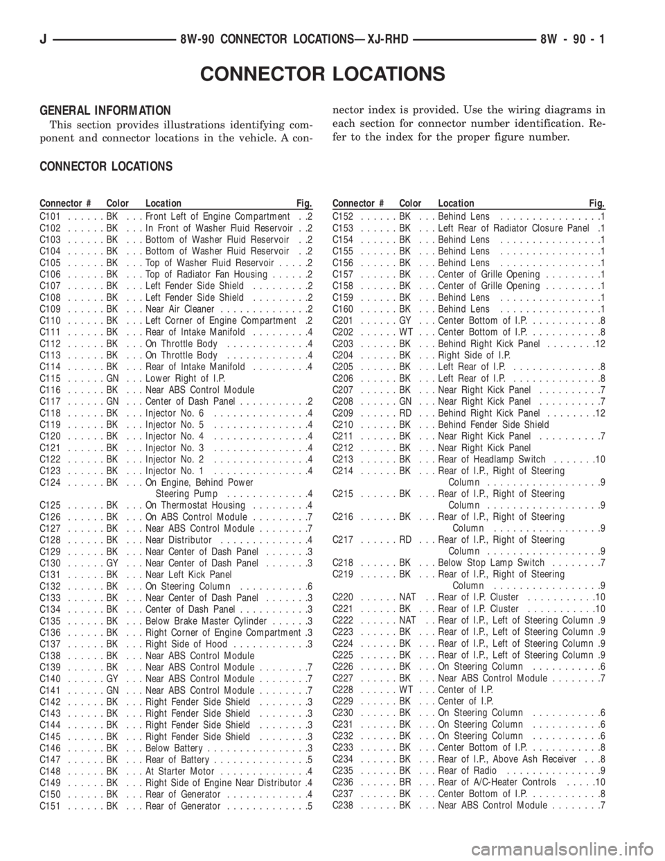
CONNECTOR LOCATIONS
GENERAL INFORMATION
This section provides illustrations identifying com-
ponent and connector locations in the vehicle. A con-nector index is provided. Use the wiring diagrams in
each section for connector number identification. Re-
fer to the index for the proper figure number.
CONNECTOR LOCATIONS
Connector # Color Location Fig.
C101......BK ...Front Left of Engine Compartment . .2
C102......BK ...InFront of Washer Fluid Reservoir . .2
C103......BK ...Bottom of Washer Fluid Reservoir . .2
C104......BK ...Bottom of Washer Fluid Reservoir . .2
C105......BK ...TopofWasher Fluid Reservoir.....2
C106......BK ...TopofRadiator Fan Housing......2
C107......BK ...Left Fender Side Shield.........2
C108......BK ...Left Fender Side Shield.........2
C109......BK ...Near Air Cleaner..............2
C110......BK ...Left Corner of Engine Compartment .2
C111......BK ...Rear of Intake Manifold.........4
C112......BK ...OnThrottle Body.............4
C113......BK ...OnThrottle Body.............4
C114......BK ...Rear of Intake Manifold.........4
C115......GN ...Lower Right of I.P.
C116......BK ...Near ABS Control Module
C117......GN ...Center of Dash Panel...........2
C118......BK ...Injector No. 6...............4
C119......BK ...Injector No. 5...............4
C120......BK ...Injector No. 4...............4
C121......BK ...Injector No. 3...............4
C122......BK ...Injector No. 2...............4
C123......BK ...Injector No. 1...............4
C124......BK ...OnEngine, Behind Power
Steering Pump.............4
C125......BK ...OnThermostat Housing.........4
C126......BK ...OnABSControl Module.........7
C127......BK ...Near ABS Control Module........7
C128......BK ...Near Distributor..............4
C129......BK ...Near Center of Dash Panel.......3
C130......GY ...Near Center of Dash Panel.......3
C131......BK ...Near Left Kick Panel
C132......BK ...OnSteering Column...........6
C133......BK ...Near Center of Dash Panel.......3
C134......BK ...Center of Dash Panel...........3
C135......BK ...Below Brake Master Cylinder......3
C136......BK ...Right Corner of Engine Compartment .3
C137......BK ...Right Side of Hood............3
C138......BK ...Near ABS Control Module
C139......BK ...Near ABS Control Module........7
C140......GY ...Near ABS Control Module........7
C141......GN ...Near ABS Control Module........7
C142......BK ...Right Fender Side Shield........3
C143......BK ...Right Fender Side Shield........3
C144......BK ...Right Fender Side Shield........3
C145......BK ...Right Fender Side Shield........3
C146......BK ...Below Battery................3
C147......BK ...Rear of Battery...............5
C148......BK ...AtStarter Motor..............4
C149......BK ...Right Side of Engine Near Distributor .4
C150......BK ...Rear of Generator.............4
C151......BK ...Rear of Generator.............5Connector # Color Location Fig.
C152......BK ...Behind Lens................1
C153......BK ...Left Rear of Radiator Closure Panel .1
C154......BK ...Behind Lens................1
C155......BK ...Behind Lens................1
C156......BK ...Behind Lens................1
C157......BK ...Center of Grille Opening.........1
C158......BK ...Center of Grille Opening.........1
C159......BK ...Behind Lens................1
C160......BK ...Behind Lens................1
C201......GY ...Center Bottom of I.P............8
C202......WT ...Center Bottom of I.P............8
C203......BK ...Behind Right Kick Panel........12
C204......BK ...Right Side of I.P.
C205......BK ...Left Rear of I.P...............8
C206......BK ...Left Rear of I.P...............8
C207......BK ...Near Right Kick Panel..........7
C208......GN ...Near Right Kick Panel..........7
C209......RD ...Behind Right Kick Panel........12
C210......BK ...Behind Fender Side Shield
C211......BK ...Near Right Kick Panel..........7
C212......BK ...Near Right Kick Panel
C213......BK ...Rear of Headlamp Switch.......10
C214......BK ...Rear of I.P., Right of Steering
Column..................9
C215......BK ...Rear of I.P., Right of Steering
Column..................9
C216......BK ...Rear of I.P., Right of Steering
Column.................9
C217......RD ...Rear of I.P., Right of Steering
Column..................9
C218......BK ...Below Stop Lamp Switch........7
C219......BK ...Rear of I.P., Right of Steering
Column.................9
C220......NAT ..Rear of I.P. Cluster...........10
C221......BK ...Rear of I.P. Cluster...........10
C222......NAT ..Rear of I.P., Left of Steering Column .9
C223......BK ...Rear of I.P., Left of Steering Column .9
C224......BK ...Rear of I.P., Left of Steering Column .9
C225......BK ...Rear of I.P., Left of Steering Column .9
C226......BK ...OnSteering Column...........6
C227......BK ...Near ABS Control Module........7
C228......WT ...Center of I.P.
C229......BK ...Center of I.P.
C230......BK ...OnSteering Column...........6
C231......BK ...OnSteering Column...........6
C232......BK ...OnSteering Column...........6
C233......BK ...Center Bottom of I.P............8
C234......BK ...Rear of I.P., Above Ash Receiver . . .8
C235......BK ...Rear of Radio...............9
C236......BR ...Rear of A/C-Heater Controls.....10
C237......BK ...Center Bottom of I.P............8
C238......BK ...Near ABS Control Module........7
J8W-90 CONNECTOR LOCATIONSÐXJ-RHD 8W - 90 - 1
Page 1174 of 2158
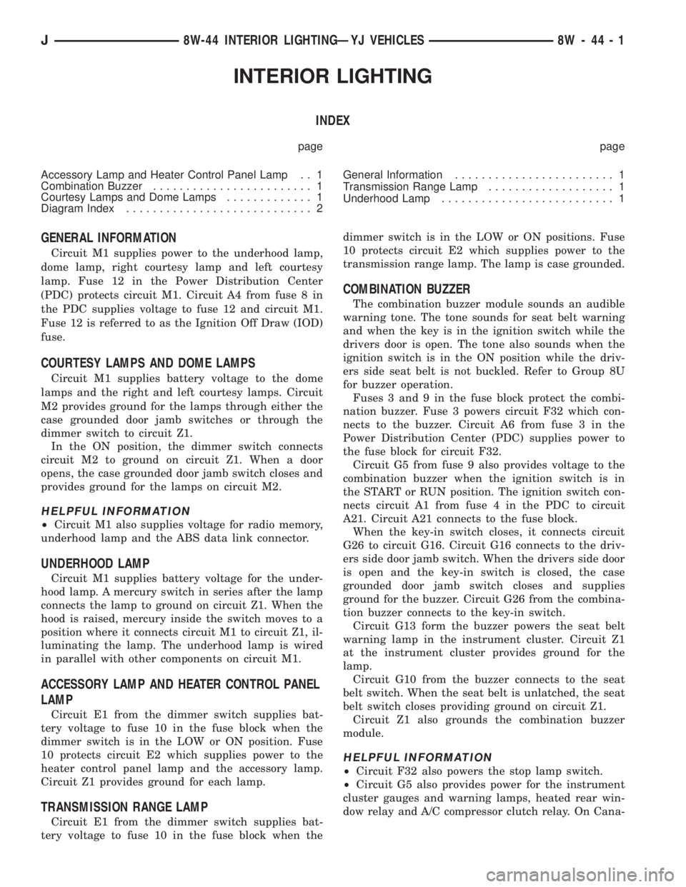
INTERIOR LIGHTING
INDEX
page page
Accessory Lamp and Heater Control Panel Lamp . . 1
Combination Buzzer........................ 1
Courtesy Lamps and Dome Lamps............. 1
Diagram Index............................ 2General Information........................ 1
Transmission Range Lamp................... 1
Underhood Lamp.......................... 1
GENERAL INFORMATION
Circuit M1 supplies power to the underhood lamp,
dome lamp, right courtesy lamp and left courtesy
lamp. Fuse 12 in the Power Distribution Center
(PDC) protects circuit M1. Circuit A4 from fuse 8 in
the PDC supplies voltage to fuse 12 and circuit M1.
Fuse 12 is referred to as the Ignition Off Draw (IOD)
fuse.
COURTESY LAMPS AND DOME LAMPS
Circuit M1 supplies battery voltage to the dome
lamps and the right and left courtesy lamps. Circuit
M2 provides ground for the lamps through either the
case grounded door jamb switches or through the
dimmer switch to circuit Z1.
In the ON position, the dimmer switch connects
circuit M2 to ground on circuit Z1. When a door
opens, the case grounded door jamb switch closes and
provides ground for the lamps on circuit M2.
HELPFUL INFORMATION
²Circuit M1 also supplies voltage for radio memory,
underhood lamp and the ABS data link connector.
UNDERHOOD LAMP
Circuit M1 supplies battery voltage for the under-
hood lamp. A mercury switch in series after the lamp
connects the lamp to ground on circuit Z1. When the
hood is raised, mercury inside the switch moves to a
position where it connects circuit M1 to circuit Z1, il-
luminating the lamp. The underhood lamp is wired
in parallel with other components on circuit M1.
ACCESSORY LAMP AND HEATER CONTROL PANEL
LAMP
Circuit E1 from the dimmer switch supplies bat-
tery voltage to fuse 10 in the fuse block when the
dimmer switch is in the LOW or ON position. Fuse
10 protects circuit E2 which supplies power to the
heater control panel lamp and the accessory lamp.
Circuit Z1 provides ground for each lamp.
TRANSMISSION RANGE LAMP
Circuit E1 from the dimmer switch supplies bat-
tery voltage to fuse 10 in the fuse block when thedimmer switch is in the LOW or ON positions. Fuse
10 protects circuit E2 which supplies power to the
transmission range lamp. The lamp is case grounded.
COMBINATION BUZZER
The combination buzzer module sounds an audible
warning tone. The tone sounds for seat belt warning
and when the key is in the ignition switch while the
drivers door is open. The tone also sounds when the
ignition switch is in the ON position while the driv-
ers side seat belt is not buckled. Refer to Group 8U
for buzzer operation.
Fuses 3 and 9 in the fuse block protect the combi-
nation buzzer. Fuse 3 powers circuit F32 which con-
nects to the buzzer. Circuit A6 from fuse 3 in the
Power Distribution Center (PDC) supplies power to
the fuse block for circuit F32.
Circuit G5 from fuse 9 also provides voltage to the
combination buzzer when the ignition switch is in
the START or RUN position. The ignition switch con-
nects circuit A1 from fuse 4 in the PDC to circuit
A21. Circuit A21 connects to the fuse block.
When the key-in switch closes, it connects circuit
G26 to circuit G16. Circuit G16 connects to the driv-
ers side door jamb switch. When the drivers side door
is open and the key-in switch is closed, the case
grounded door jamb switch closes and supplies
ground for the buzzer. Circuit G26 from the combina-
tion buzzer connects to the key-in switch.
Circuit G13 form the buzzer powers the seat belt
warning lamp in the instrument cluster. Circuit Z1
at the instrument cluster provides ground for the
lamp.
Circuit G10 from the buzzer connects to the seat
belt switch. When the seat belt is unlatched, the seat
belt switch closes providing ground on circuit Z1.
Circuit Z1 also grounds the combination buzzer
module.
HELPFUL INFORMATION
²Circuit F32 also powers the stop lamp switch.
²Circuit G5 also provides power for the instrument
cluster gauges and warning lamps, heated rear win-
dow relay and A/C compressor clutch relay. On Cana-
J8W-44 INTERIOR LIGHTINGÐYJ VEHICLES 8W - 44 - 1