1995 JEEP YJ hood open
[x] Cancel search: hood openPage 1085 of 2158
SPLICE LOCATIONS
GENERAL INFORMATION
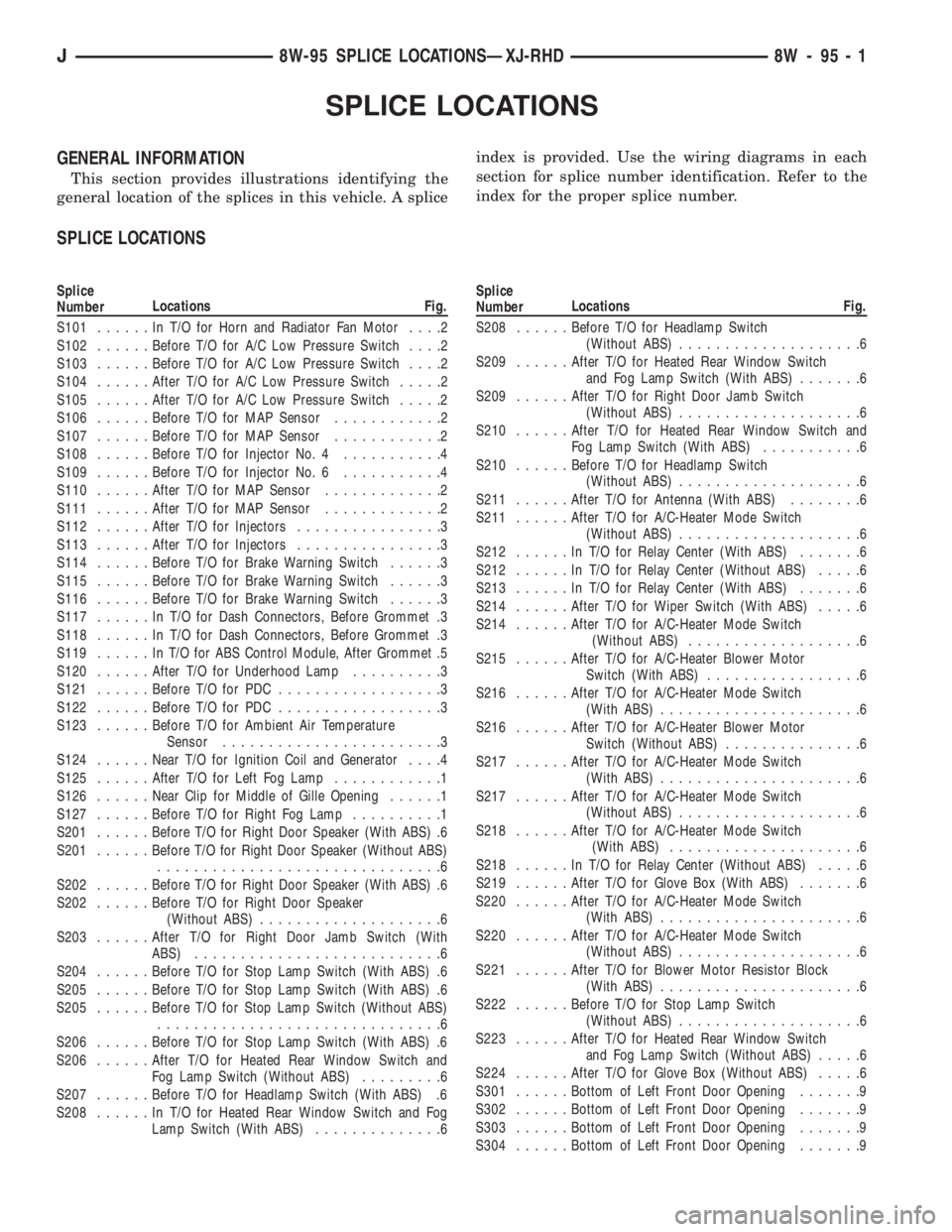
This section provides illustrations identifying the
general location of the splices in this vehicle. A spliceindex is provided. Use the wiring diagrams in each
section for splice number identification. Refer to the
index for the proper splice number.
SPLICE LOCATIONS
Splice
NumberLocations Fig.
S101......InT/OforHorn and Radiator Fan Motor....2
S102......Before T/O for A/C Low Pressure Switch....2
S103......Before T/O for A/C Low Pressure Switch....2
S104......After T/O for A/C Low Pressure Switch.....2
S105......After T/O for A/C Low Pressure Switch.....2
S106......Before T/O for MAP Sensor............2
S107......Before T/O for MAP Sensor............2
S108......Before T/O for Injector No. 4...........4
S109......Before T/O for Injector No. 6...........4
S110......After T/O for MAP Sensor.............2
S111......After T/O for MAP Sensor.............2
S112......After T/O for Injectors................3
S113......After T/O for Injectors................3
S114......Before T/O for Brake Warning Switch......3
S115......Before T/O for Brake Warning Switch......3
S116......Before T/O for Brake Warning Switch......3
S117......InT/OforDash Connectors, Before Grommet .3
S118......InT/OforDash Connectors, Before Grommet .3
S119......InT/OforABSControl Module, After Grommet .5
S120......After T/O for Underhood Lamp..........3
S121......Before T/O for PDC..................3
S122......Before T/O for PDC..................3
S123......Before T/O for Ambient Air Temperature
Sensor........................3
S124......Near T/O for Ignition Coil and Generator....4
S125......After T/O for Left Fog Lamp............1
S126......Near Clip for Middle of Gille Opening......1
S127......Before T/O for Right Fog Lamp..........1
S201......Before T/O for Right Door Speaker (With ABS) .6
S201......Before T/O for Right Door Speaker (Without ABS)
...............................6
S202......Before T/O for Right Door Speaker (With ABS) .6
S202......Before T/O for Right Door Speaker
(Without ABS)....................6
S203......After T/O for Right Door Jamb Switch (With
ABS)...........................6
S204......Before T/O for Stop Lamp Switch (With ABS) .6
S205......Before T/O for Stop Lamp Switch (With ABS) .6
S205......Before T/O for Stop Lamp Switch (Without ABS)
...............................6
S206......Before T/O for Stop Lamp Switch (With ABS) .6
S206......After T/O for Heated Rear Window Switch and
Fog Lamp Switch (Without ABS).........6
S207......Before T/O for Headlamp Switch (With ABS) .6
S208......InT/OforHeated Rear Window Switch and Fog
Lamp Switch (With ABS)..............6Splice
NumberLocations Fig.
S208......Before T/O for Headlamp Switch
(Without ABS)....................6
S209......After T/O for Heated Rear Window Switch
and Fog Lamp Switch (With ABS).......6
S209......After T/O for Right Door Jamb Switch
(Without ABS)....................6
S210......After T/O for Heated Rear Window Switch and
Fog Lamp Switch (With ABS)...........6
S210......Before T/O for Headlamp Switch
(Without ABS)....................6
S211......After T/O for Antenna (With ABS)........6
S211......After T/O for A/C-Heater Mode Switch
(Without ABS)....................6
S212......InT/OforRelay Center (With ABS).......6
S212......InT/OforRelay Center (Without ABS).....6
S213......InT/OforRelay Center (With ABS).......6
S214......After T/O for Wiper Switch (With ABS).....6
S214......After T/O for A/C-Heater Mode Switch
(Without ABS)...................6
S215......After T/O for A/C-Heater Blower Motor
Switch (With ABS).................6
S216......After T/O for A/C-Heater Mode Switch
(With ABS)......................6
S216......After T/O for A/C-Heater Blower Motor
Switch (Without ABS)...............6
S217......After T/O for A/C-Heater Mode Switch
(With ABS)......................6
S217......After T/O for A/C-Heater Mode Switch
(Without ABS)....................6
S218......After T/O for A/C-Heater Mode Switch
(With ABS).....................6
S218......InT/OforRelay Center (Without ABS).....6
S219......After T/O for Glove Box (With ABS).......6
S220......After T/O for A/C-Heater Mode Switch
(With ABS)......................6
S220......After T/O for A/C-Heater Mode Switch
(Without ABS)....................6
S221......After T/O for Blower Motor Resistor Block
(With ABS)......................6
S222......Before T/O for Stop Lamp Switch
(Without ABS)....................6
S223......After T/O for Heated Rear Window Switch
and Fog Lamp Switch (Without ABS).....6
S224......After T/O for Glove Box (Without ABS).....6
S301......Bottom of Left Front Door Opening.......9
S302......Bottom of Left Front Door Opening.......9
S303......Bottom of Left Front Door Opening.......9
S304......Bottom of Left Front Door Opening.......9
J8W-95 SPLICE LOCATIONSÐXJ-RHD 8W - 95 - 1
Page 1174 of 2158
INTERIOR LIGHTING
INDEX
page page
Accessory Lamp and Heater Control Panel Lamp . . 1
Combination Buzzer........................ 1
Courtesy Lamps and Dome Lamps............. 1
Diagram Index............................ 2General Information........................ 1
Transmission Range Lamp................... 1
Underhood Lamp.......................... 1
GENERAL INFORMATION
Circuit M1 supplies power to the underhood lamp,
dome lamp, right courtesy lamp and left courtesy
lamp. Fuse 12 in the Power Distribution Center
(PDC) protects circuit M1. Circuit A4 from fuse 8 in
the PDC supplies voltage to fuse 12 and circuit M1.
Fuse 12 is referred to as the Ignition Off Draw (IOD)
fuse.
COURTESY LAMPS AND DOME LAMPS
Circuit M1 supplies battery voltage to the dome
lamps and the right and left courtesy lamps. Circuit
M2 provides ground for the lamps through either the
case grounded door jamb switches or through the
dimmer switch to circuit Z1.
In the ON position, the dimmer switch connects
circuit M2 to ground on circuit Z1. When a door
opens, the case grounded door jamb switch closes and
provides ground for the lamps on circuit M2.
HELPFUL INFORMATION
²Circuit M1 also supplies voltage for radio memory,
underhood lamp and the ABS data link connector.
UNDERHOOD LAMP
Circuit M1 supplies battery voltage for the under-
hood lamp. A mercury switch in series after the lamp
connects the lamp to ground on circuit Z1. When the
hood is raised, mercury inside the switch moves to a
position where it connects circuit M1 to circuit Z1, il-
luminating the lamp. The underhood lamp is wired
in parallel with other components on circuit M1.
ACCESSORY LAMP AND HEATER CONTROL PANEL
LAMP
Circuit E1 from the dimmer switch supplies bat-
tery voltage to fuse 10 in the fuse block when the
dimmer switch is in the LOW or ON position. Fuse
10 protects circuit E2 which supplies power to the
heater control panel lamp and the accessory lamp.
Circuit Z1 provides ground for each lamp.
TRANSMISSION RANGE LAMP
Circuit E1 from the dimmer switch supplies bat-
tery voltage to fuse 10 in the fuse block when thedimmer switch is in the LOW or ON positions. Fuse
10 protects circuit E2 which supplies power to the
transmission range lamp. The lamp is case grounded.
COMBINATION BUZZER
The combination buzzer module sounds an audible
warning tone. The tone sounds for seat belt warning
and when the key is in the ignition switch while the
drivers door is open. The tone also sounds when the
ignition switch is in the ON position while the driv-
ers side seat belt is not buckled. Refer to Group 8U
for buzzer operation.
Fuses 3 and 9 in the fuse block protect the combi-
nation buzzer. Fuse 3 powers circuit F32 which con-
nects to the buzzer. Circuit A6 from fuse 3 in the
Power Distribution Center (PDC) supplies power to
the fuse block for circuit F32.
Circuit G5 from fuse 9 also provides voltage to the
combination buzzer when the ignition switch is in
the START or RUN position. The ignition switch con-
nects circuit A1 from fuse 4 in the PDC to circuit
A21. Circuit A21 connects to the fuse block.
When the key-in switch closes, it connects circuit
G26 to circuit G16. Circuit G16 connects to the driv-
ers side door jamb switch. When the drivers side door
is open and the key-in switch is closed, the case
grounded door jamb switch closes and supplies
ground for the buzzer. Circuit G26 from the combina-
tion buzzer connects to the key-in switch.
Circuit G13 form the buzzer powers the seat belt
warning lamp in the instrument cluster. Circuit Z1
at the instrument cluster provides ground for the
lamp.
Circuit G10 from the buzzer connects to the seat
belt switch. When the seat belt is unlatched, the seat
belt switch closes providing ground on circuit Z1.
Circuit Z1 also grounds the combination buzzer
module.
HELPFUL INFORMATION
²Circuit F32 also powers the stop lamp switch.
²Circuit G5 also provides power for the instrument
cluster gauges and warning lamps, heated rear win-
dow relay and A/C compressor clutch relay. On Cana-
J8W-44 INTERIOR LIGHTINGÐYJ VEHICLES 8W - 44 - 1
Page 1281 of 2158
minutes). The use of a locating dowel is recom-
mended during assembly to prevent smearing the
material off location.
Mopar Gasket Maker should be applied sparingly
to one gasket surface. The sealant diameter should
be 1.00 mm (0.04 inch) or less. Be certain the mate-
rial surrounds each mounting hole. Excess material
can easily be wiped off. Components should be
torqued in place within 15 minutes. The use of a lo-
cating dowel is recommended during assembly to pre-
vent smearing the material off location.
ENGINE PERFORMANCE
To provide best vehicle performance and lowest ve-
hicle emissions, it is most important that the tune-up
be done accurately. Use the specifications listed on
the Vehicle Emission Control Information label found
on the engine compartment hood.
(1) Test battery specific gravity. Add water, if nec-
essary. Clean and tighten battery connections.
(2) Test cranking amperage draw (refer to Group
8B, Battery/Starter Service for the proper proce-
dures).
(3) Tighten the intake manifold bolts (refer to
Group 11, Exhaust System and Intake Manifold for
the proper specifications).
(4) Perform cylinder compression test:
(a) Check engine oil level and add oil, if neces-
sary.
(b) Drive the vehicle until engine reaches normal
operating temperature.
(c) Select a route free from traffic and other
forms of congestion, observe all traffic laws and
briskly accelerate through the gears several times.
The higher engine speed may help clean out valve
seat deposits which can prevent accurate compres-
sion readings.
CAUTION: DO NOT overspeed the engine.
(d) Remove all spark plugs from engine. As spark
plugs are being removed, check electrodes for ab-
normal firing indicatorsÐfouled, hot, oily, etc.
Record cylinder number of spark plug for future
reference.
(e) Disconnect coil wire from distributor and se-
cure to good ground to prevent a spark from start-
ing a fire.
(f) Be sure throttle blades are fully open during
the compression check.
(g) Insert compression gage adaptor into the
No.1 spark plug hole. Crank engine until maximum
pressure is reached on gauge. Record this pressure
as No.1 cylinder pressure.
(h) Repeat Step 4g for all remaining cylinders.
(i) Compression should not be less than 689 kPa
(100 psi) and not vary more than 172 kPa (25 psi)
from cylinder to cylinder.(j) If cylinder(s) have abnormally low compres-
sion pressures, repeat steps 4a through 4h.
(k) If the same cylinder(s) repeat an abnormally
low reading, it could indicate the existence of a
problem in the cylinder.
The recommended compression pressures are
to be used only as a guide to diagnosing engine
problems. An engine should NOT be disassem-
bled to determine the cause of low compression
unless some malfunction is present.
(5) Clean or replace spark plugs as necessary. Ad-
just gap (refer to Group 8D, Ignition System for gap
adjustment and torque).
(6) Test resistance of spark plug cables (refer to
Group 8D, Ignition System).
(7) Inspect the primary wire. Test coil output volt-
age, primary and secondary resistance. Replace parts
as necessary (refer to Group 8D, Ignition System and
make necessary adjustment).
(8) Perform a combustion analysis.
(9) Test fuel pump for pressure (refer to Group 14,
Fuel System for the proper specifications).
(10) Inspect air filter element (refer to Group 0,
Lubrication and Maintenance for the proper proce-
dure).
(11) Inspect crankcase ventilation system (refer to
Group 0, Lubrication and Maintenance for the proper
procedure).
(12) For emission controls refer to Group 25, Emis-
sion Controls System for service procedures.
(13) Inspect and adjust accessory belt drives (refer
to Group 7, Cooling System for the proper adjust-
ments).
(14) Road test vehicle as a final test.
HONING CYLINDER BORES
Before honing, stuff plenty of clean shop towels un-
der the bores and over the crankshaft to keep abra-
sive materials from entering the crankshaft area.
(1) Used carefully, the Cylinder Bore Sizing Hone
C-823 equipped with 220 grit stones, is the best tool
for this job. In addition to deglazing, it will reduce
taper and out-of-round as well as removing light
scuffing, scoring or scratches. Usually a few strokes
will clean up a bore and maintain the required lim-
its.
CAUTION: DO NOT use rigid type hones to remove
cylinder wall glaze.
(2) Deglazing of the cylinder walls may be done if
the cylinder bore is straight and round. Use a cylin-
der surfacing hone, Honing Tool C-3501, equipped
with 280 grit stones (C-3501-3810). 20-60 strokes, de-
pending on the bore condition, will be sufficient to
provide a satisfactory surface. Using honing oil
C-3501-3880 or a light honing oil available from ma-
jor oil distributors.
9 - 2 ENGINESJ
Page 1756 of 2158
(6) Apply bead of Loctite 599 sealer to oil pan seal-
ing surface. Sealer bead should be at least 3 mm (1/8
in.) wide. Then install pan and tighten pan bolts to 7
Nzm (65 in. lbs.) torque.
(7) Install new gasket on oil pan drain plug. Install
and tighten plug to 20 Nzm (15 ft. lbs.) torque.
(8) Connect cable to engine bracket and throttle
linkage.
(9) Fill transmission with Mopar Dexron/Mercon
IIE.
(10) Adjust the cable as described in cable adjust-
ment procedure.
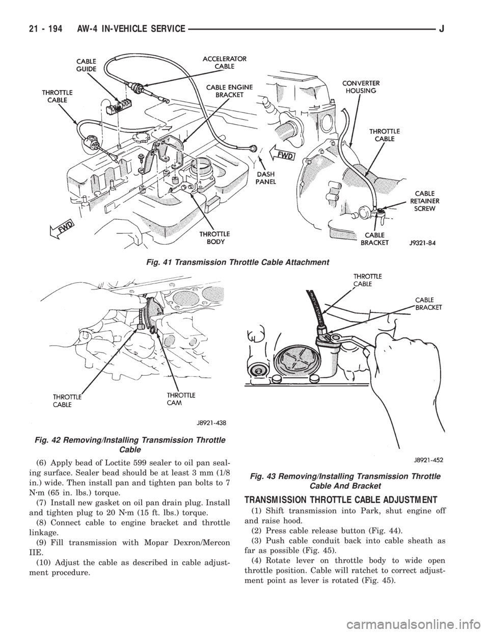
TRANSMISSION THROTTLE CABLE ADJUSTMENT
(1) Shift transmission into Park, shut engine off
and raise hood.
(2) Press cable release button (Fig. 44).
(3) Push cable conduit back into cable sheath as
far as possible (Fig. 45).
(4) Rotate lever on throttle body to wide open
throttle position. Cable will ratchet to correct adjust-
ment point as lever is rotated (Fig. 45).
Fig. 43 Removing/Installing Transmission Throttle
Cable And Bracket
Fig. 41 Transmission Throttle Cable Attachment
Fig. 42 Removing/Installing Transmission Throttle
Cable
21 - 194 AW-4 IN-VEHICLE SERVICEJ
Page 1921 of 2158
EXTERIOR COMPONENTS
INDEX
page page
Air Exhaust GrilleÐXJ...................... 25
Battery TrayÐXJ.......................... 14
Body Side Molding/CladdingÐXJ.............. 20
Body Stripes/DecalsÐXJ.................... 21
Brush GuardÐXJ.......................... 3
Cowl Grille and ScreenÐXJ................. 12
Cowl Weatherstrip Seal/Crossmember Air
DeflectorÐXJ........................... 11
Dash Panel Insulator PanelÐXJ.............. 12
Drip Rail MoldingÐXJ...................... 25
Exterior NameplatesÐXJ................... 26
External MirrorsÐXJ....................... 27
Front FenderÐXJ......................... 14
Fuel Filler Door BumpersÐXJ................ 27Fuel Filler Nozzle/TubeÐXJ................. 26
Grille and Grille Opening Panel (GOP)ÐXJ....... 3
Hood AdjustmentÐXJ...................... 10
Hood Hinge ReplacementÐXJ............... 10
Hood Latch ReplacementÐXJ................ 11
Hood Latch Striker ReplacementÐXJ.......... 11
HoodÐXJ................................ 7
Latch Release Cable ReplacementÐXJ......... 11
Luggage RackÐXJ........................ 28
Quarter Window AppliqueÐXJ................ 25
Radiator Support CrossmemberÐXJ............ 6
Rear Wheelhouse Flares and LinersÐXJ........ 19
Safety Latch Striker ReplacementÐXJ.......... 11
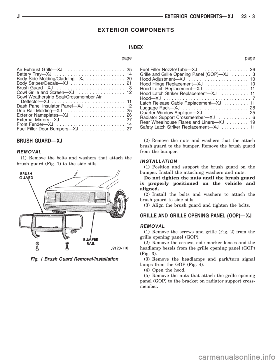
BRUSH GUARDÐXJ
REMOVAL
(1) Remove the bolts and washers that attach the
brush guard (Fig. 1) to the side sills.(2) Remove the nuts and washers that the attach
brush guard to the bumper. Remove the brush guard
from the bumper.INSTALLATION
(1) Position and support the brush guard on the
bumper. Install the attaching washers and nuts.
Do not tighten the nuts until the brush guard
is properly positioned on the vehicle and
aligned.
(2) Install the bolts and washers to attach the
brush guard to side sills.
(3) Align the brush guard and tighten the bolts.
GRILLE AND GRILLE OPENING PANEL (GOP)ÐXJ
REMOVAL
(1) Remove the screws and grille (Fig. 2) from the
grille opening panel (GOP).
(2) Remove the screws, side marker lenses and the
headlamp bezels from the grille opening panel (GOP)
(Fig. 3).
(3) Remove the headlamps and park/turn signal
lamps from the GOP (Fig. 4).
(4) Open the hood.
(5) Remove the nuts that attach the grille opening
panel (GOP) to the bracket on radiator support cross-
member.
Fig. 1 Brush Guard Removal/Installation
JEXTERIOR COMPONENTSÐXJ 23 - 3
Page 1925 of 2158
INSTALLATION
(1) If removed, install the horns, baffle braces and
the wire harnesses on the baffles (Fig. 11).
(2) Position the radiator and the radiator support
crossmember at the front of vehicle (Fig. 10). Install
and tighten screws to 9 Nzm (76 in-lbs) torque.
(3) For 2.5L engines, install the power steering
pump reservoir on the left filler panel (Fig. 9).
(4) Install the grille opening panel (GOP).
HOODÐXJ
The hood service procedures included in this sec-
tion include:
²Hood removal and installation.
²Hood adjustment.
²HingeÐlatchÐstriker service (Fig. 12).
²Latch release cable service.
JEXTERIOR COMPONENTSÐXJ 23 - 7
Page 1929 of 2158
(2) Install the hinge nuts on the studs. Tighten the
restraint cable nut to 4 Nzm (38 in-lbs) torque.
Tighten the remaining nuts to 9 Nzm (77 in-lbs)
torque.
If a replacement hinge seal is being installed,
position it around the hinge arm, force it
against the hinge base.
(3) Position the hinge seal around the hinge arm
and on hinge base.
(4) Install the hood.
(5) Adjust the hood as necessary.
HOOD LATCH REPLACEMENTÐXJ
REMOVAL
(1) Remove the screw that attaches the latch to the
hood inner panel (Fig. 15).
(2) Disconnect the latch from the hood and latch
connecting rod. Remove the latch from the hood.
INSTALLATION
(1) Connect the latch to the latch connecting rod
and position it on the hood inner panel.
(2) Install the screw that attaches the latch to the
hood inner panel.
(3) Tighten the screw to 9 Nzm (77 in-lbs) torque.
(4) Test the operation of the latch release cable and
latch.
HOOD LATCH STRIKER REPLACEMENTÐXJ
REMOVE
(1) Remove the grille opening panel (GOP).
(2) Remove the screws that attach the striker to
the radiator baffle (Fig. 19).
(3) Remove the striker and shims from the baffle.
INSTALLATION
(1) Position the shims and striker on the radiator
baffle and install the screws.
(2) Tighten the screws to 21 Nzm (15 ft-lbs) torque.
(3) Test the striker/hood alignment by opening and
closing the hood several times. Adjust the striker, if
necessary.
LATCH RELEASE CABLE REPLACEMENTÐXJ
REMOVAL
(1) Drill out the bellcrank to hood rivet heads and
remove the rivets (Fig. 14).
(2) Disconnect the bellcrank from the latch rod and
the latch release cable. Remove the bellcrank from
the hood.
(3) Disconnect the latch release cable from the
clips on the hood.
(4) Remove the left cowl side trim panel.
(5) Remove the cable bracket screws from the cowl
side panel.(6) Pull the cable through the dash panel and re-
move it from under the instrument panel.
INSTALLATION
(1) Insert the replacement cable end through the
hole in the dash panel into the engine compartment.
(2) Pull the cable forward and seat the grommet in
the dash panel.
(3) Position the cable bracket on the cowl side
panel and install the screws. Tighten the screws to
13 Nzm (111 in-lbs) torque.
(4) Install the left cowl side trim panel.
(5) Connect the cable and latch rod to the
bellcrank.
(6) Position the bellcrank on the hood and install
the rivets.
(7) Attach the cable to the clips.
(8) Test release the cable for proper operation.
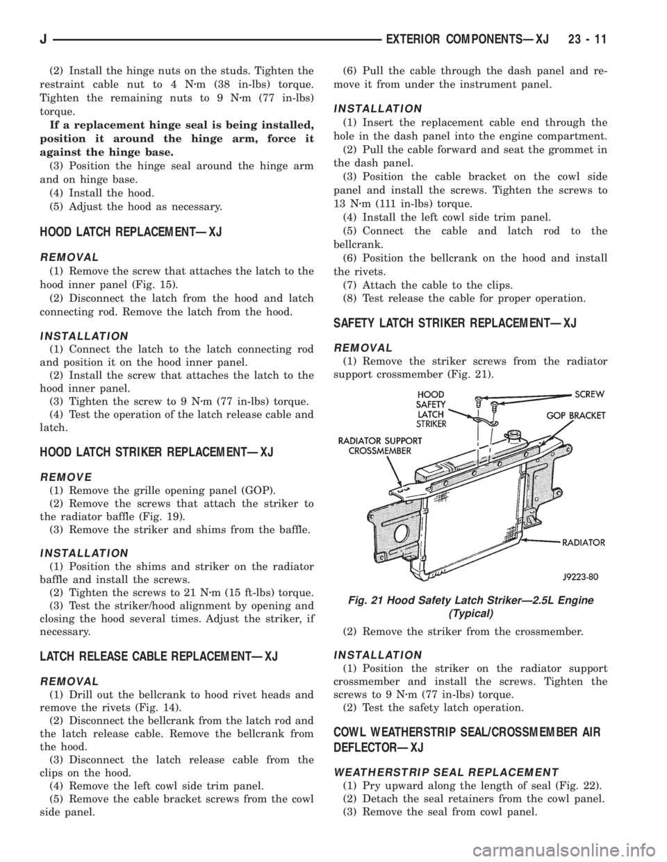
SAFETY LATCH STRIKER REPLACEMENTÐXJ
REMOVAL
(1) Remove the striker screws from the radiator
support crossmember (Fig. 21).
(2) Remove the striker from the crossmember.
INSTALLATION
(1) Position the striker on the radiator support
crossmember and install the screws. Tighten the
screws to 9 Nzm (77 in-lbs) torque.
(2) Test the safety latch operation.
COWL WEATHERSTRIP SEAL/CROSSMEMBER AIR
DEFLECTORÐXJ
WEATHERSTRIP SEAL REPLACEMENT
(1) Pry upward along the length of seal (Fig. 22).
(2) Detach the seal retainers from the cowl panel.
(3) Remove the seal from cowl panel.
Fig. 21 Hood Safety Latch StrikerÐ2.5L Engine
(Typical)
JEXTERIOR COMPONENTSÐXJ 23 - 11
Page 1935 of 2158
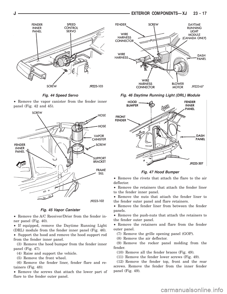
²Remove the vapor canister from the fender inner
panel (Fig. 42 and 45).
²Remove the A/C Receiver/Drier from the fender in-
ner panel (Fig. 40).
²If equipped, remove the Daytime Running Light
(DRL) module from the fender inner panel (Fig. 46).
²Support the hood and remove the hood support rod
from the fender inner panel.
(3) Remove the hood bumper from the fender inner
panel (Fig. 47).
(4) Raise and support the vehicle.
(5) Remove the front wheel.
(6) Remove the fender liner, fender flare and re-
tainers (Fig. 48):
²Remove the screws that attach the lower part of
flare to the fender outer panel.²Remove the rivets that attach the flare to the air
deflector.
²Remove the retainers that attach the fender liner
to the fender inner panel.
²Remove the nuts that attach the fender liner to
the fender outer panel and flare retainers.
²Remove the fender liner from between the fender
panels.
²Remove the push-nuts that attach the retainers to
the fender outer panel.
²Remove the retainers and flare from the fender
outer panel.
(7) Remove the grille opening panel (GOP).
(8) Remove the air deflector.
(9) Remove the rocker panel molding from the
fender.
(10) Remove all the fender braces (Fig. 49).
(11) Remove the fender lower screws (Fig. 49).
(12) Remove the fender top, front and the rear
screws. Remove the fender from the inner fender
panel (Fig. 49).
Fig. 44 Speed Servo
Fig. 45 Vapor Canister
Fig. 46 Daytime Running Light (DRL) Module
Fig. 47 Hood Bumper
JEXTERIOR COMPONENTSÐXJ 23 - 17