1995 JEEP YJ clutch
[x] Cancel search: clutchPage 1900 of 2158
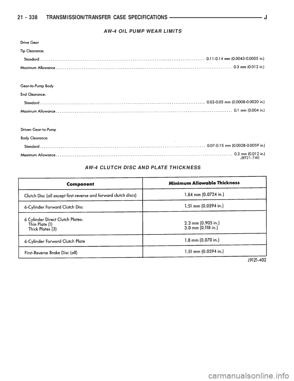
AW-4 OIL PUMP WEAR LIMITS
AW-4 CLUTCH DISC AND PLATE THICKNESS
21 - 338 TRANSMISSION/TRANSFER CASE SPECIFICATIONSJ
Page 1903 of 2158
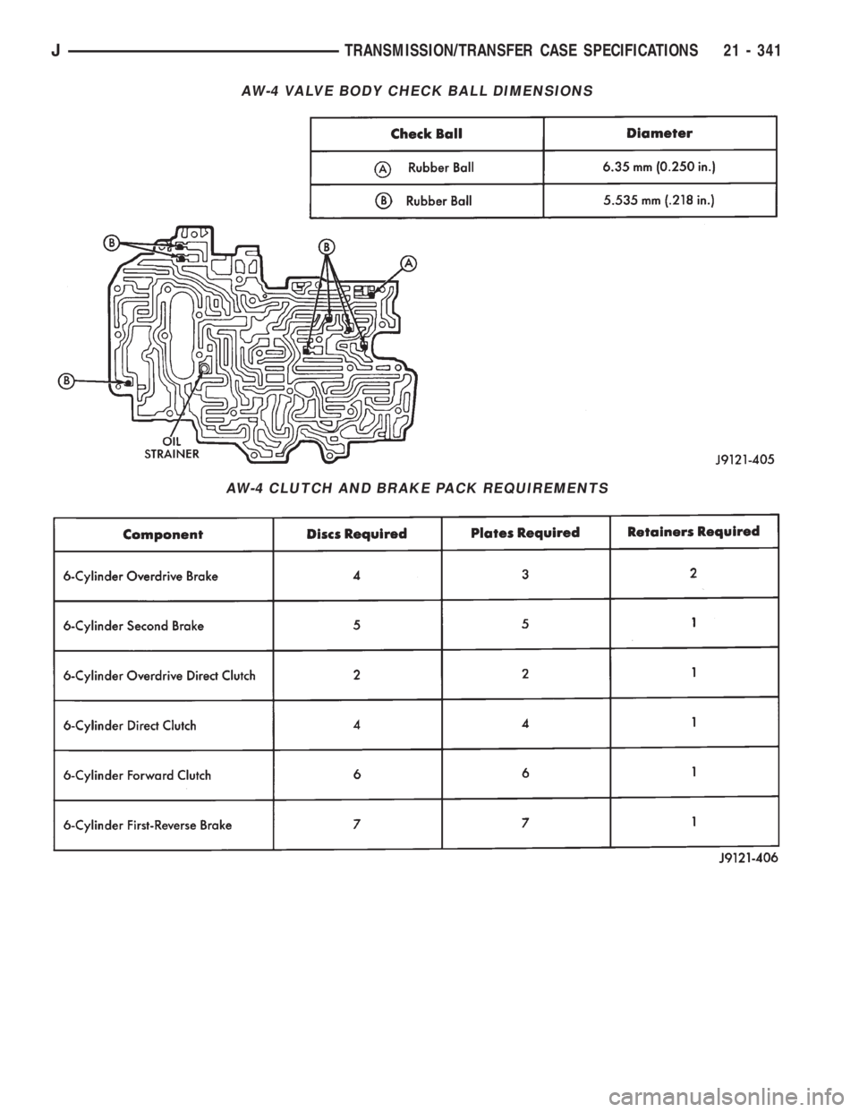
AW-4 VALVE BODY CHECK BALL DIMENSIONS
AW-4 CLUTCH AND BRAKE PACK REQUIREMENTS
JTRANSMISSION/TRANSFER CASE SPECIFICATIONS 21 - 341
Page 2084 of 2158
motor is controlled by a vacuum switch in the heater
control panel. The vent air doors are opened and
closed by a cable and linkage operated by the air con-
trol lever. Fresh air intake occurs only when the le-
ver is in the VENT position.
AIR CONDITIONING
The compressor increases the pressure and temper-
ature of the refrigerant. The heated refrigerant vapor
is pumped into the condenser where it is cooled by
air passing over the condenser fins. As the refriger-
ant cools in the condenser, it condenses into a liquid.
Still under high pressure, the liquid refrigerant
passes into the receiver. The receiver acts as a reser-
voir to furnish refrigerant to the expansion valve at
all times. From the receiver, the high pressure liquid
refrigerant passes to the expansion valve. The expan-
sion valve meters refrigerant into the evaporator.
The low pressure is maintained by the suction side of
the compressor. As it enters the evaporator, the re-
frigerant begins to absorb heat from the air passing
over the evaporator core. Having given up its heat to
boil the refrigerant, the air is cooled and passes into
the passenger compartment. From the evaporator the
vaporized refrigerant is drawn back to the compres-
sor to repeat the cycle.
A/C COMPONENTS
COMPRESSOR:The SD7H15 Compressor is used
on all models. The purpose of the compressor is to
compress the low-pressure refrigerant vapor into a
high pressure, high temperature vapor. The compres-
sor is serviced as a assembly only.
CLUTCH PULLEY AND COIL:They are
mounted on the compressor and providing a way to
drive the compressor. The compressor clutch and coil
are the only serviced parts on the SD7H15 compres-
sor. When the compressor is not in operation, the
pulley free wheels on the clutch hub bearing. When
the coil is energized the clutch plate is magnetically
engaged with the pulley and turns the compressor
shaft.
CONDENSER:The condenser is located in front of
the engine radiator. Its function is to cool the hot
high pressure refrigerant gas. This causes it to con-
dense into high pressure liquid refrigerant.
EXPANSION VALVE:The expansion valve is lo-
cated in the engine compartment on XJ vehicles. On
YJ vehicles it is located behind the A/C housing. Its
function is to meter refrigerant into the evaporator in
accordance with cooling requirements.
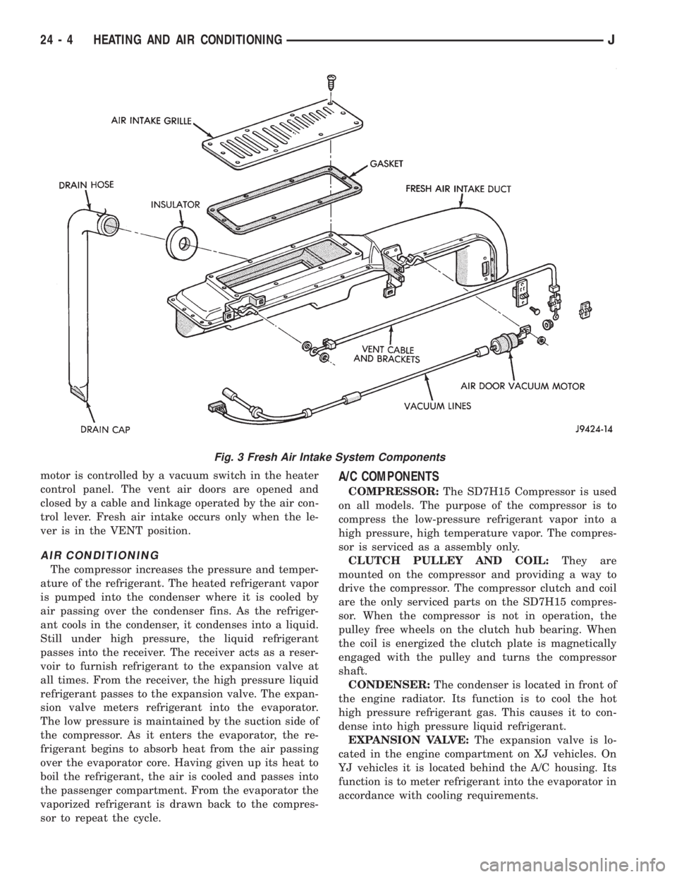
Fig. 3 Fresh Air Intake System Components
24 - 4 HEATING AND AIR CONDITIONINGJ
Page 2087 of 2158
EVAPORATOR COIL:The coil is located in the
A/C housing. Its function is to remove heat and de-
humidify the air before it enters the vehicle.
FIN SENSING CYCLING CLUTCH SWITCH:
The switch is attached to the evaporator coil with the
temperature sensing probe inserted into the coil fins.
This switch controls evaporator temperature and pre-
vents condensate water on the evaporator coil from
freezing. It does this by sending signals to the Pow-
ertrain Control Module (PCM) to cycling the com-
pressor clutch on and off. This switch is used onXJ
only.
FILTER-DRIER:The drier is used to remove any
traces of moisture from the refrigerant system. A
sight glass is located on top of the filter drier. It is
used as a diagnostic tool to observe refrigerant flow.
HIGH PRESSURE RELIEF VALVE:The valve is
located on the filter drier. The valve is used to pre-
vent excessive high pressure build of 3445 to 4135
kPa (500 to 600 psi) and above. This prevents dam-
age to the compressor and other system components.
LOW-PRESSURE HIGH-PRESSURE CUT-OFF
SWITCH:The switch is located on the filter drier
and is wired in series with compressor clutch. When
the pressure drops down to 193 kPa (28 psi) the
switch interrupts the power to the compressor clutch.
When the pressure increases above 3100 to 3375 kPa
(450 to 490 psi) the switch interrupts the power to
the compressor clutch.
THERMOSTAT:The thermostat is located in the
evaporator housing. The thermostat temperature
sensing probe is inserted into the evaporator coil. Its
function is to cycles the compressor clutch on and off.
This switch controls temperature and prevents con-
densate water on the evaporator coil from freezing.
The thermostat is used on theYJonly.
REFRIGERANT LINES:The lines are used to
carry the refrigerant between the various system
components.
SERVICE PORTS:The high pressure service port
is located on the discharge line near the compressor.
The low pressure service port is located on the suc-
tion line near the compressor. These ports are used
to attach A/C gauges. After servicing the refrigerant
system, always install service port caps.
REFRIGERANT
XJ and YJ vehicles use a new type of refrigerant
called R-134a. It is a non-toxic, non-flammable, clear
color-less liquified gas.
R-134a refrigerant is not compatible with R-12 re-
frigerant. A small amount of R-12 in a R-134a system
will cause compressor failure, oil sludge or poor air
conditioning performance.R-134a refrigerant requires a special type of com-
pressor oil (SP20 PAG). When adding oil, make sure
that it is designed to be used in a R-134a system and
the SD7H15 compressor.
Service ports have been designed to ensure that
the system is not accidentally filled with R-12 refrig-
erant.
REFRIGERANT EQUIPMENT
WARNING: EYE PROTECTION MUST BE USED
WHEN SERVICING AN AIR CONDITIONING REFRIG-
ERANT SYSTEM. TURN OFF (ROTATE CLOCKWISE)
ALL VALVES ON THE EQUIPMENT BEING USED
BEFORE PROCEEDING WITH THIS OPERATION.
PERSONNEL INJURY CAN RESULT.
Chrysler Corporation recommends a (R-134a) recy-
cling device that meets SAE standard J2210 be used
when servicing the refrigerant system. Contact an
automotive service equipment supplier for refrigerant
recycling equipment that is available in your area.
Refer to the operating instructions provided with the
recycling equipment for proper operation.
MANIFOLD GAUGE SET
CAUTION: DO NOT use an R-12 manifold gauge set
on an R-134a system. The refrigerants are not com-
patible and system damage will result.
A manifold gauge set (Fig. 1) may be needed in
conjunction with the charging and or recovery/recy-
cling device. The service hoses on the gauge set being
used should have manual (turn wheel) or automatic
back flow valves at the service port connector ends.
This will prevent refrigerant from being release into
the atmosphere.
LOW PRESSURE GAUGE HOSE
The low pressure hose (BLUE with BLACK STRIP)
should be attached to the charging/service port. This
port is located at the right front of the engine com-
partment in the condenser-to-evaporator line.
HIGH PRESSURE GAUGE HOSE
The high pressure hose (RED with BLACK STRIP)
should be attached to the discharge/service port. This
port is located on the compressor plumbing or mani-
fold.
RECOVERY/RECYCLING/EVACUATION/
CHARGING HOSE
The center manifold hose (YELLOW or WHITE
with BLACK STRIP) is used to recover, evacuate and
charge the refrigerant system. When the low or high
pressure valves on the manifold gauge set are
opened, the refrigerant in the system will escape
through this hose.
JHEATING AND AIR CONDITIONING 24 - 7
Page 2092 of 2158
REFRIGERANT OIL
It is important to have the correct amount of oil in
the A/C system. This will ensure proper lubrication of
the compressor. Too little oil will result in damage to
the compressor. Too much oil will reduce the cooling
capacity of the system.
The oil used in the SD7H15 compressor is a poly-
alkylene glycol synthetic oil SP-20 PAG, wax-free re-
frigerant oil. Only refrigerant oil of the same type
should be used to service the system. Do not use any
other oil. The oil container should be kept tightly
capped until it is ready for use and then capped after
use to prevent contamination. Refrigerant oil will
quickly absorb any moisture it comes in contact with.
OIL LEVEL CHECK
It will not be necessary to check oil level in the
compressor or to add oil unless there has been an oil
loss. This may be due to a rupture or leak from a
line, shaft seal, evaporator or condenser. Oil loss at a
leak point will be evident by the presence of a wet,
shiny surface around the leak.
When an A/C system is assembled at the factory,
all components (except the compressor) are refriger-
ant oil free. After the system has been charged and
operated, the oil in the compressor is dispersed
through the system. The receiver-drier, evaporator,
condenser and compressor will retain a significant
amount of oil.
Refrigerant oil must be added when a receiver-
drier, evaporator, condenser or compressor are re-
placed. When the compressor is replaced, the oil
must be drained from the replaced compressor and
measured. Drain all the oil from the new compressor.
Add back into the new compressor the amount of oil
that was drained out of the old compressor.
Add an additional 30 ml (1 fluid oz.) of com-
pressor oil to the system when a receiver-drier,
condenser or evaporator is replaced.
AIR CONDITIONING PERFORMANCE TESTS
Humidity has an important bearing on the temper-
ature of the air delivered to the vehicle's interior. It
is important to understand the effect humidity has
on the performance of the system. When humidity is
high, the evaporator has to perform a double duty. It
must lower the air temperature and the temperature
of the moisture carried in the air. Condensing the
moisture in the air transfers a great deal of heat en-
ergy into the evaporator fins and tubing. This re-
duces the amount of heat the evaporator can absorb
from the air. High humidity greatly reduces the evap-
orator's ability to lower the temperature of the air.Evaporator capacity used to reduce the amount of
moisture in the air is not wasted. Wringing some of
the moisture out of the air entering the vehicle adds
to the comfort of the passengers. However, an owner
may expect too much from their air conditioning sys-
tem on humid days. A performance test is the best
way to determine whether or not the system is per-
forming up to standard. This test also provides valu-
able clues to the possible cause of trouble.
Air temperature in test room must be 21ÉC (70ÉF)
minimum for this test.
(1) Connect a Tachometer and manifold gauge set.
(2) Set A/C controls to Max A/C, temperature lever
on full cool and blower on high.
(3) Start engine and adjust idle to 1,000 RPM with
A/C clutch engaged.
(4) Engine should be warmed up with doors, win-
dows and hood closed.
(5) Insert a thermometer in the left center A/C out-
let. Operate the A/C and engine for 5 minutes. The
A/C clutch may cycle depending on ambient temper-
atures.
(6) After 5 minutes note the discharge air temper-
ature. If the clutch cycles, take the reading before
the clutch disengages.
(7) On LHD XJ vehicles open the hood and discon-
nect vacuum line going to the heater water control
valve. Observe the valve arm for movement as the
line is disconnected. Plug the vacuum line to prevent
leakage. If it does not move repair vacuum circuit.
(8) Operate the A/C for 2 more minutes and take
the discharge air temperature reading again. On XJ
vehicles if the temperature increased by more than
2ÉC (5ÉF) check the blend air door cable for correct
operation.
(9) Compare the discharge air temperature to the
A/C Performance (Temperature and Pressure) Chart.
If the discharge air temperature is high, refer to Re-
frigerant Leak Testing and Refrigerant System Diag-
nosis Chart.
(10) Compare the compressor discharge and suc-
tion pressures to the A/C Performance (Temperature
and Pressure) Chart. If the compressor discharge or
suction pressure is not normal, check the operation of
the refrigerant system. Refer to Refrigerant System
Diagnosis Chart.
If pressures are abnormal, refer to the Pressure
and Performance Diagnosis Charts.
The following chart have been developed for quick
reference.
24 - 12 HEATING AND AIR CONDITIONINGJ
Page 2095 of 2158
HEATING AND AIR CONDITIONING TEST PROCEDURES
INDEX
page page
A/C Compressor Clutch..................... 15
A/C Compressor Clutch Relay................ 15
A/C Compressor Clutch Relay................ 16
Air Conditioning ControlsÐXJ Vehicles......... 15
Air Conditioning ControlsÐYJ Vehicles......... 16
Blower Motor............................ 17
Blower Motor Switch....................... 16Compressor Clutch........................ 16
Fin Sensing Cycling Clutch Switch............. 15
Heater Diagnosis......................... 17
Low-Pressure High-Pressure Cut-Off Switch..... 15
Low-Pressure High-Pressure Cut-Off Switch..... 16
Thermostatic Control....................... 16
AIR CONDITIONING CONTROLSÐXJ VEHICLES
The A/C Compressor Clutch is controlled by several
components: the Pressure Cut-Off Switch, Cycling
Clutch Switch, Clutch Relay and Powertrain Control
Module (PCM).
Powertrain Control Module may delay A/C clutch
engagement up to 30 seconds.
Refer to Group 8W Wiring Diagrams for wiring and
terminals. Use volt ohmmeter to test switches.
A/C COMPRESSOR CLUTCH
The clutch assembly consists of a stationary elec-
tromagnetic coil, hub bearing pulley assembly, and
clutch plate. When the coil is energized the plate is
magnetically engaged with the pulley and turns the
compressor shaft.
A/C COMPRESSOR CLUTCH TEST
(1) Unplug clutch coil connector.
(2) Connect a jumper wire from the battery posi-
tive post to the clutch coil terminal. The clutch
should engage, if not leave jumper wire connected
and go to next step.
(3) Connect a jumper wire from clutch coil frame to
chassis ground. The clutch should engage if not re-
pair clutch coil ground or replace coil.
A/C COMPRESSOR CLUTCH RELAY
The A/C compressor clutch relay controls the 12-
volt source to the A/C clutch. The relay is activated
when the PCM receives a A/C request signal from the
fin-sensed cycling clutch switch. The PCM then sends
a ground signal to the relay. The relay is activated
and sends 12-volts to the clutch coil which energizes
the clutch. The relay is located in the power distribu-
tion center.
COMPRESSOR CLUTCH RELAY TEST
For test procedure refer to Powertrain Diagnostic
Service Manual for A/C clutch relay circuit test.
LOW-PRESSURE HIGH-PRESSURE CUT-OFF
SWITCH
The pressure cut-off switch is located on the filter
drier and is wired in series with compressor clutch.
The switch interrupts the power to the compressor
clutch circuit when the pressure drops to 193 kPa (28
psi) or increases above 3100 to 3375 kPa (450 to 490
psi).
PRESSURE CUT-OFF SWITCH TEST
(1) Verify system has correct refrigerant charge.
(2) Turn ignition switch to RUN, A/C blower switch
to ON and control set to MAX.
(3) Unplug pressure cut-off switch and test feed
circuit from select switch. It should be battery volt-
age if not, repair open to select switch.
(4) Test for continuity between the switch termi-
nals. If continuity is not present recover refrigerant
from the system. Replace switch, evacuate and re-
charge system.
FIN SENSING CYCLING CLUTCH SWITCH
The switch is attached to the evaporator coil with
the temperature sensing probe inserted into the coil
fins. This switch prevents condensate water on the
evaporator coil from freezing. It does this by sending
signals to the PCM to cycling the compressor clutch
on and off.
FIN-SENSED CYCLING CLUTCH SWITCH TEST
Test area ambient temperature should be around
21ÉC (70ÉF) for test.
(1) Verify system has correct refrigerant charge.
(2) Start Engine and turn on A/C.
(3) If the compressor clutch cycles ON and OFF 2
to 3 times per minute the cycling clutch switch is
normal. The ambient temperature should be between
20ÉC-30ÉC (68ÉF-90ÉF). Above 32ÉC (90ÉF) the com-
pressor clutch may stay engaged (non cycling) due to
the high heat load, this condition is normal. If the
compressor clutch fails to engage go to next step.
(4) Disconnect wiring harness connector from
switch. With a volt meter test feed circuit from cut-
JHEATING AND AIR CONDITIONING 24 - 15
Page 2096 of 2158
off switch for battery voltage. If no voltage is present
test pressure cut-off switch. If voltage is present go
to next step.
(5) With ohmmeter test harness connector ground
circuit for continuity to ground. If circuit is open, (no
continuity) repair ground circuit. If circuit test OK
and clutch does not engage refer to Powertrain Diag-
nostic Service Manual for A/C clutch circuit test.
AIR CONDITIONING CONTROLSÐYJ VEHICLES
The air conditioning circuit consists of 3 segments;
battery supply, blower motor and compressor clutch.
The 3 segments have a common connection point at
the blower switch.
The power supply circuit extends from the HTR/
FAN fuse to the blower switch. From the blower
switch, battery feed is routed to the blower motor
and compressor clutch circuit.
Refer to Group 8W Wiring Diagrams for wiring
schematic and terminals. Use volt ohmmeter to test
switches.
COMPRESSOR CLUTCH
The clutch assembly consists of a stationary elec-
tromagnetic coil, hub bearing pulley assembly, and
clutch plate. When the coil is energized the plate is
magnetically engaged with the pulley and turns the
compressor shaft.
COMPRESSOR CLUTCH TEST
(1) Unplug clutch coil connector.
(2) Connect jumper wire from battery positive post
to clutch coil connector. The clutch should engage, if
not leave jumper wire connected and go to next step.
(3) Connect jumper wire from clutch coil frame to
chassis ground. The clutch should engage, if not re-
pair clutch coil ground or replace coil.
A/C COMPRESSOR CLUTCH RELAY
The A/C compressor clutch relay controls the 12-
volt source to the A/C clutch. The relay is activated
when the PCM receives a A/C request signal. The
PCM then sends a ground signal to the relay. The re-
lay is activated and sends 12-volts to the clutch coil
which energizes the clutch. The relay is located in
the power distribution center.
COMPRESSOR CLUTCH RELAY TEST
For test procedure refer to Powertrain Diagnostic
Service Manual for A/C clutch relay circuit test.
LOW-PRESSURE HIGH-PRESSURE CUT-OFF
SWITCH
The pressure cut-off switch is located on the filter
drier and is wired in series with compressor clutch.
The switch interrupts the power to the compressorclutch circuit when the pressure drops to 193 kPa (28
psi) or increases above 3100 to 3375 kPa (450 to 490
psi).
PRESSURE CUT-OFF SWITCH TEST
(1) Turn ignition switch to RUN, A/C blower switch
to ON and control set to MAX.
(2) Unplug pressure cut-off switch connector and
test feed circuit from the thermostatic, should be bat-
tery voltage. If not, proceed to thermostatic control
tests.
(3) Test for continuity between the switch termi-
nals. If continuity is not present recover refrigerant
system, replace switch, evacuate and recharge sys-
tem.
THERMOSTATIC CONTROL
Cycling of the compressor and therefore the tem-
perature of the outlet air is regulated by the thermo-
static control. A thermal sensor extends from the
control to the evaporator housing. When the temper-
ature of the evaporator drops below the set tempera-
ture, the thermostatic control opens the clutch
circuit. The circuit remains open until evaporator
temperature rises above the set temperature.
THERMOSTATIC CONTROL TEST
(1) Turn ignition switch to RUN, A/C blower switch
to ON and thermostatic control set to MAX cool.
(2) Test thermostatic control feed terminal from
blower switch, should be battery voltage. If not re-
pair open from blower switch.
(3) Test thermostatic control output terminal to
pressure cut-out switch, should be battery voltage. If
not, replace thermostatic control.
BLOWER MOTOR SWITCH
The blower switch controls blower motor speed.
The blower motor segment consists of the 3 wires
from the blower switch to the motor. Through the
switch, the 3 wires connect the motor brushes to bat-
tery supply. When connected to battery feed, the sep-
arate brushes provide the 3 blower speeds LO, MED,
and HIGH.
BLOWER MOTOR SWITCH TEST
(1) Turn ignition to RUN position.
(2) Test battery side of fuse for battery voltage. If
not, repair open from ignition switch.
(3) Test A/C blower switch feed circuit from fuse
box should be battery voltage. If not, repair open
from fuse panel.
(4) Test A/C blower switch LO terminal with
blower switch in LO, should be battery voltage. If
not, replace switch.
(5) Test A/C blower switch MED terminal with
blower switch in MED, should be battery voltage. If
not, replace switch.
24 - 16 HEATING AND AIR CONDITIONINGJ
Page 2099 of 2158
COMPRESSOR SERVICE
DESCRIPTION
The A/C system uses a Sanden SD7H15 compres-
sor. The compressor is a 7 piston design.
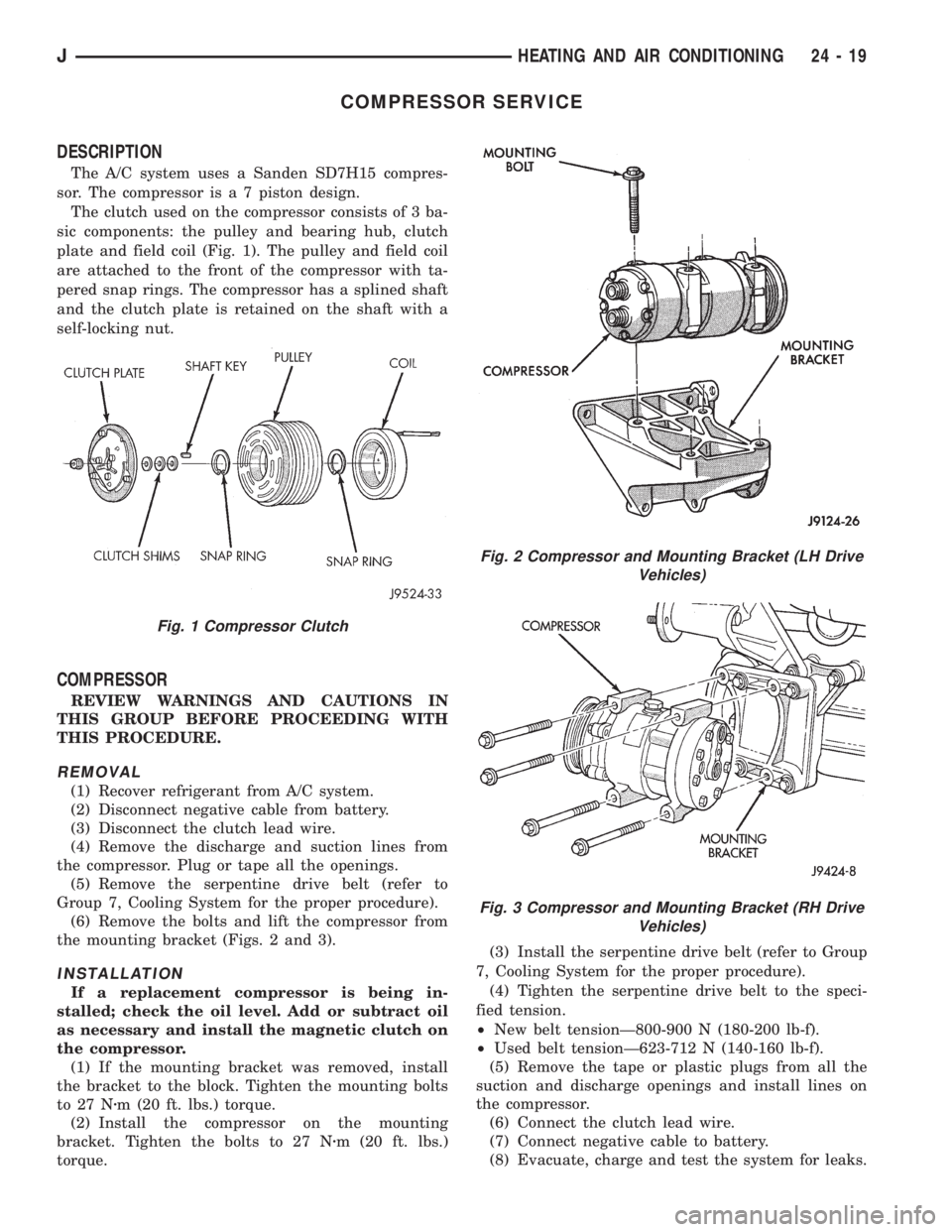
The clutch used on the compressor consists of 3 ba-
sic components: the pulley and bearing hub, clutch
plate and field coil (Fig. 1). The pulley and field coil
are attached to the front of the compressor with ta-
pered snap rings. The compressor has a splined shaft
and the clutch plate is retained on the shaft with a
self-locking nut.
COMPRESSOR
REVIEW WARNINGS AND CAUTIONS IN
THIS GROUP BEFORE PROCEEDING WITH
THIS PROCEDURE.
REMOVAL
(1) Recover refrigerant from A/C system.
(2) Disconnect negative cable from battery.
(3) Disconnect the clutch lead wire.
(4) Remove the discharge and suction lines from
the compressor. Plug or tape all the openings.
(5) Remove the serpentine drive belt (refer to
Group 7, Cooling System for the proper procedure).
(6) Remove the bolts and lift the compressor from
the mounting bracket (Figs. 2 and 3).
INSTALLATION
If a replacement compressor is being in-
stalled; check the oil level. Add or subtract oil
as necessary and install the magnetic clutch on
the compressor.
(1) If the mounting bracket was removed, install
the bracket to the block. Tighten the mounting bolts
to 27 Nzm (20 ft. lbs.) torque.
(2) Install the compressor on the mounting
bracket. Tighten the bolts to 27 Nzm (20 ft. lbs.)
torque.(3) Install the serpentine drive belt (refer to Group
7, Cooling System for the proper procedure).
(4) Tighten the serpentine drive belt to the speci-
fied tension.
²New belt tensionÐ800-900 N (180-200 lb-f).
²Used belt tensionÐ623-712 N (140-160 lb-f).
(5) Remove the tape or plastic plugs from all the
suction and discharge openings and install lines on
the compressor.
(6) Connect the clutch lead wire.
(7) Connect negative cable to battery.
(8) Evacuate, charge and test the system for leaks.
Fig. 1 Compressor Clutch
Fig. 2 Compressor and Mounting Bracket (LH Drive
Vehicles)
Fig. 3 Compressor and Mounting Bracket (RH Drive
Vehicles)
JHEATING AND AIR CONDITIONING 24 - 19