1995 JEEP YJ window
[x] Cancel search: windowPage 499 of 2158
DEFOGGER SWITCH
With defogger switch connector separated from de-
fogger switch; turn ignition switch to ON for voltage
tests, or turn ignition switch to OFF for resistance
tests.
(1) Measure voltage at defogger switch connector
terminal D. The meter should read approximately 5
volts momentarily. If OK, go to next step. If not OK,
repair open from relay.
(2) Refer to switch diagram for resistance tests. If
not OK, replace defogger switch.
DEFOGGER RELAY
With defogger relay connector separated from de-
fogger relay; turn ignition switch to ON for voltage
tests, or turn ignition switch to OFF for resistance
tests.
(1) Measure voltage at relay connector terminal 4.
The meter should read battery voltage. If OK, go to
next step. If not OK, repair open from fuse 18 (XJ) or
fuse 9 (YJ).(2) Measure voltage at relay connector terminal 5.
The meter should read battery voltage. If OK, go to
next step. If not OK, repair open from fuse 8 (XJ), or
fuse 6 (YJ).
(3) Measure resistance between relay connector
terminal 1 and left side (driver's side) of defogger
grid. The meter should read zero ohms. If OK, go to
next step. If not OK, repair open between relay con-
nector and left side of defogger grid.
(4) Measure resistance between relay connector
terminal 2 and a clean chassis ground. The meter
should read zero ohms. If OK, go to next step. If not
OK, repair open between relay connector and ground.
(5) Connect relay connector and measure voltage
at terminal 3. The meter should read approximately
5 volts. If not OK, replace defogger relay.
SERVICE PROCEDURES
REAR WINDOW GLASS GRID REPAIRS
The repair of grid lines, bus bars or pigtail wires
can be accomplished using the MOPAR Rear Window
Defogger Repair Kit (P/N 4267922) or equivalent.
WARNING: MATERIALS CONTAINED IN REPAIR KIT
MAY CAUSE SKIN OR EYE IRRITATION. CONTAINS
EPOXY RESIN AND AMINE TYPE HARDENER,
HARMFUL IF SWALLOWED. AVOID CONTACT WITH
SKIN AND EYES. FOR SKIN, WASH AFFECTED AR-
EAS WITH SOAP AND WATER. DO NOT TAKE IN-
TERNALLY. IF TAKEN INTERNALLY, INDUCE
VOMITING; CALL A PHYSICIAN IMMEDIATELY. IF IN
CONTACT WITH EYES, FLUSH WITH PLENTY OF
WATER. USE WITH ADEQUATE VENTILATION. DO
NOT USE NEAR FIRE OR FLAME. CONTENTS CON-
TAIN 3% FLAMMABLE SOLVENTS. KEEP OUT OF
REACH OF CHILDREN.
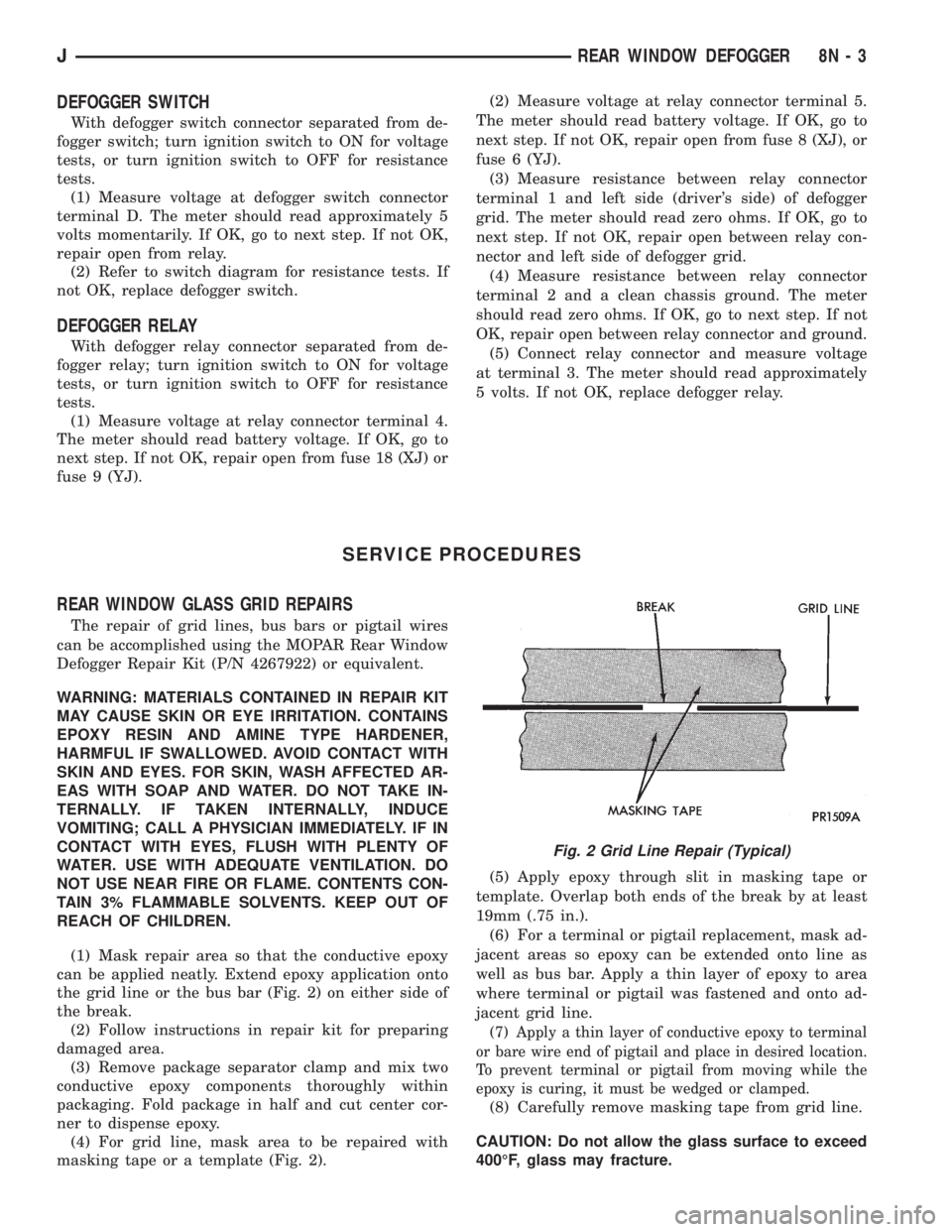
(1) Mask repair area so that the conductive epoxy
can be applied neatly. Extend epoxy application onto
the grid line or the bus bar (Fig. 2) on either side of
the break.
(2) Follow instructions in repair kit for preparing
damaged area.
(3) Remove package separator clamp and mix two
conductive epoxy components thoroughly within
packaging. Fold package in half and cut center cor-
ner to dispense epoxy.
(4) For grid line, mask area to be repaired with
masking tape or a template (Fig. 2).(5) Apply epoxy through slit in masking tape or
template. Overlap both ends of the break by at least
19mm (.75 in.).
(6) For a terminal or pigtail replacement, mask ad-
jacent areas so epoxy can be extended onto line as
well as bus bar. Apply a thin layer of epoxy to area
where terminal or pigtail was fastened and onto ad-
jacent grid line.
(7) Apply a thin layer of conductive epoxy to terminal
or bare wire end of pigtail and place in desired location.
To prevent terminal or pigtail from moving while the
epoxy is curing, it must be wedged or clamped.
(8) Carefully remove masking tape from grid line.
CAUTION: Do not allow the glass surface to exceed
400ÉF, glass may fracture.
Fig. 2 Grid Line Repair (Typical)
JREAR WINDOW DEFOGGER 8N - 3
Page 500 of 2158
(9) Allow epoxy to cure 24 hours at room tempera-
ture or use heat gun with a 260É-371ÉC (500É-700ÉF)
range for 15 minutes. Hold gun approximately
254mm (10 inches) from repaired area.
(10) After conductive epoxy is properly cured re-
move wedge or clamp from terminal or pigtail and
check operation of rear window defogger. Do not at-
tach connectors until curing is complete.
DEFOGGER SWITCH REMOVE/INSTALL
XJ MODELS
(1) Remove the instrument cluster bezel. Refer to
Group 8E - Instrument Panel and Gauges for proce-
dure.
(2) Remove the switch housing panel.
(3) Unplug the switch connector. Slightly depress
the switch mounting tabs and remove the switch.
(4) Reverse removal procedures to install.
YJ MODELS
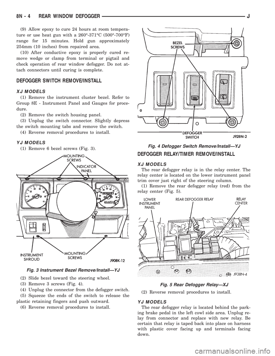
(1) Remove 6 bezel screws (Fig. 3).
(2) Slide bezel toward the steering wheel.
(3) Remove 3 screws (Fig. 4).
(4) Unplug the connector from the defogger switch.
(5) Squeeze the ends of the switch to release the
plastic retaining fingers and push outward.
(6) Reverse removal procedures to install.
DEFOGGER RELAY/TIMER REMOVE/INSTALL
XJ MODELS
The rear defogger relay is in the relay center. The
relay center is located on the lower instrument panel
trim cover just right of the steering column.
(1) Remove the rear defogger relay (red) from the
relay center (Fig. 5).
(2) Reverse removal procedures to install.
YJ MODELS
The rear defogger relay is located behind the park-
ing brake pedal in the left cowl side area. Unplug re-
lay from connector and replace with new relay. Be
certain that relay is taped back into place on harness
with plastic cover facing up and terminals facing
down.
Fig. 3 Instrument Bezel Remove/InstallÐYJ
Fig. 4 Defogger Switch Remove/InstallÐYJ
Fig. 5 Rear Defogger RelayÐXJ
8N - 4 REAR WINDOW DEFOGGERJ
Page 501 of 2158

POWER LOCKS
CONTENTS
page page
DIAGNOSIS............................. 2
GENERAL INFORMATION.................. 1SERVICE PROCEDURES................... 8
GENERAL INFORMATION
Power locks are optional equipment on XJ (Chero-
kee) models. Power windows and the keyless entry
system are included on vehicles equipped with the
power lock option. All doors and the liftgate can be
locked and unlocked electrically by operating the
switch on either front door panel, or by operating the
lock and unlock buttons of the remote keyless entry
transmitter. The power lock and keyless entry sys-
tems operate with battery power supplied indepen-
dent of the ignition switch.
Following are general descriptions of the major
components in the power lock system. Refer to Group
8W - Wiring Diagrams for complete circuit descrip-
tions and diagrams. Refer to the owner's manual for
more information on the features and use of these
systems.
POWER LOCK SWITCH
The power locks are controlled by a two-way switch
mounted on the trim panel of each front door. The
switch controls battery feed to the lock and unlock
relays. The door lock switches can not be repaired. If
faulty, the entire switch must be replaced.
POWER LOCK/UNLOCK RELAYS
The power lock and unlock relays are located in the
relay center. The relay center is located on the lower
instrument panel reinforcement behind the lower in-
strument panel and just right of the steering column.
The relays respond to inputs from the power lock
switches and the keyless entry module by sending
the correct battery and ground feeds to the lock mo-
tors. The lock and unlock relays can not be repaired.
If faulty, they must be replaced.
POWER LOCK MOTOR
The locks are actuated by a reversible motor
mounted within each door. The motor direction iscontrolled by the battery and ground feeds from the
power lock/unlock relays. The motor can not be re-
paired. If faulty, the entire motor must be replaced.
KEYLESS ENTRY TRANSMITTER
The keyless entry transmitter is equipped with two
buttons labeled Lock and Unlock. It is also designed
to serve as a key fob and is equipped with a key ring.
Each transmitter has a different vehicle access code,
which must be programmed into the memory of the
keyless entry module in the vehicle in order to oper-
ate the locks. The operating range of the infrared
transmitter signal is up to 4.75 meters (15 feet) from
the receiver.
The transmitter operates on two CR1616 3-volt (or
equivalent) batteries. Typical battery life is from one
to two years.
KEYLESS ENTRY MODULE
The keyless entry module is mounted in a housing
on the headliner near the windshield between the
sunvisors, or inside and towards the rear of the over-
head console (if equipped). This module contains the
keyless entry receiver and program logic for the key-
less entry system.
The keyless entry module has a memory function
to retain the vehicle access code of at least one, and
up to four transmitters. The module receives input
from the remote keyless entry transmitter. In re-
sponse to that input, it is programmed to control out-
puts to the lock and unlock relays. The module can
not be repaired and, if faulty, must be replaced.
JPOWER LOCKS 8P - 1
Page 508 of 2158
SERVICE PROCEDURES
KEYLESS ENTRY TRANSMITTER
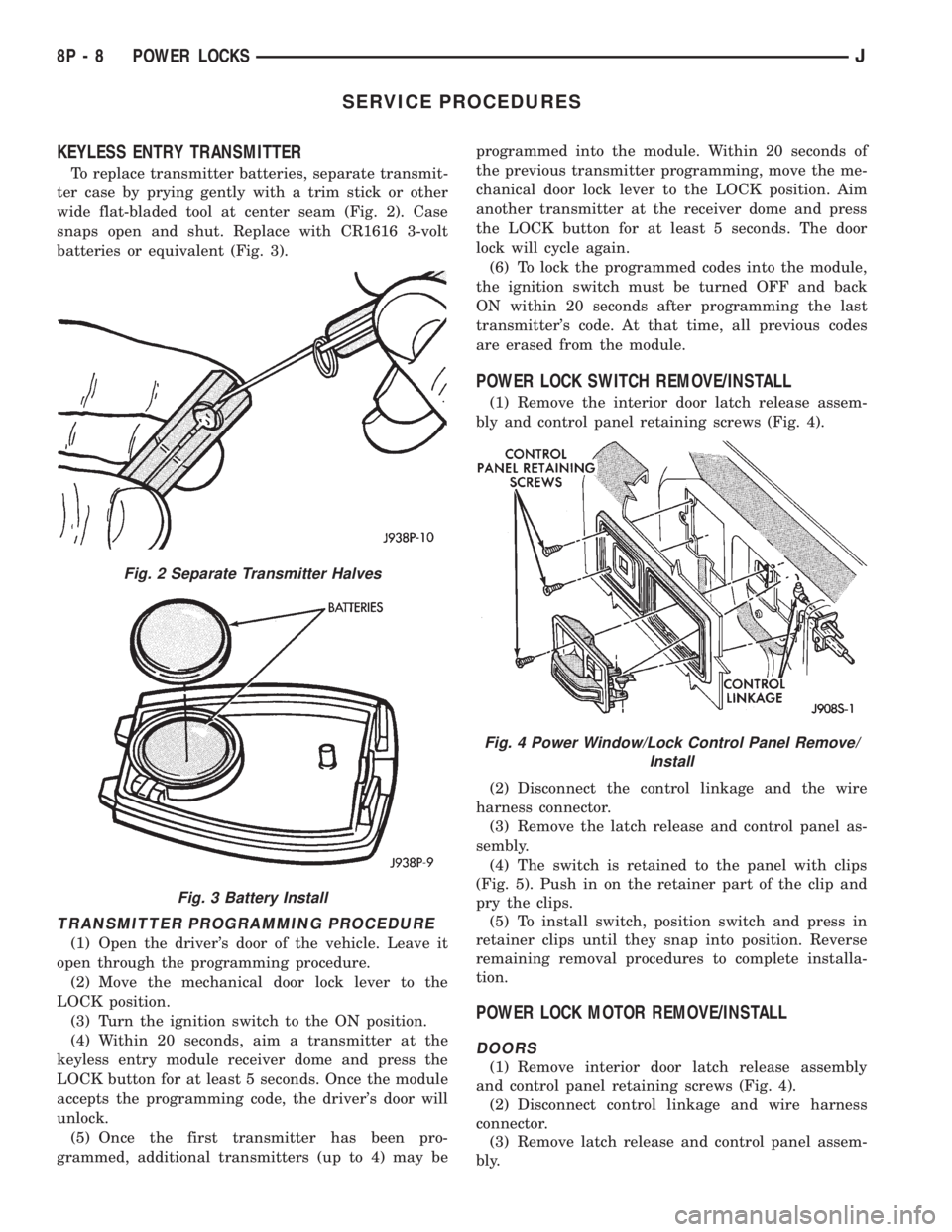
To replace transmitter batteries, separate transmit-
ter case by prying gently with a trim stick or other
wide flat-bladed tool at center seam (Fig. 2). Case
snaps open and shut. Replace with CR1616 3-volt
batteries or equivalent (Fig. 3).
TRANSMITTER PROGRAMMING PROCEDURE
(1) Open the driver's door of the vehicle. Leave it
open through the programming procedure.
(2) Move the mechanical door lock lever to the
LOCK position.
(3) Turn the ignition switch to the ON position.
(4) Within 20 seconds, aim a transmitter at the
keyless entry module receiver dome and press the
LOCK button for at least 5 seconds. Once the module
accepts the programming code, the driver's door will
unlock.
(5) Once the first transmitter has been pro-
grammed, additional transmitters (up to 4) may beprogrammed into the module. Within 20 seconds of
the previous transmitter programming, move the me-
chanical door lock lever to the LOCK position. Aim
another transmitter at the receiver dome and press
the LOCK button for at least 5 seconds. The door
lock will cycle again.
(6) To lock the programmed codes into the module,
the ignition switch must be turned OFF and back
ON within 20 seconds after programming the last
transmitter's code. At that time, all previous codes
are erased from the module.
POWER LOCK SWITCH REMOVE/INSTALL
(1) Remove the interior door latch release assem-
bly and control panel retaining screws (Fig. 4).
(2) Disconnect the control linkage and the wire
harness connector.
(3) Remove the latch release and control panel as-
sembly.
(4) The switch is retained to the panel with clips
(Fig. 5). Push in on the retainer part of the clip and
pry the clips.
(5) To install switch, position switch and press in
retainer clips until they snap into position. Reverse
remaining removal procedures to complete installa-
tion.
POWER LOCK MOTOR REMOVE/INSTALL
DOORS
(1) Remove interior door latch release assembly
and control panel retaining screws (Fig. 4).
(2) Disconnect control linkage and wire harness
connector.
(3) Remove latch release and control panel assem-
bly.
Fig. 2 Separate Transmitter Halves
Fig. 3 Battery Install
Fig. 4 Power Window/Lock Control Panel Remove/
Install
8P - 8 POWER LOCKSJ
Page 517 of 2158
POWER WINDOWS
CONTENTS
page page
DIAGNOSIS............................. 1
GENERAL INFORMATION.................. 1SERVICE PROCEDURES................... 7
GENERAL INFORMATION
Power door windows are optional equipment on XJ
(Cherokee) models. The power windows operate only
with the ignition switch in the ON position. This
group covers diagnosis and service of the electrical
components peculiar to the power window system.
For service of mechanical components such as the
regulator, lift plate or window tracks refer to Group
23 - Body Components.
Following are general descriptions of the major
components in the power window system. Refer to
Group 8W - Wiring Diagrams for complete circuit de-
scriptions and diagrams.
POWER WINDOW SWITCH
Both front and rear door windows can be raised or
lowered electrically by operating the four two-way
switches on the driver's door panel. A single two-way
switch on each passenger's door panel operates only
the window on that passenger's door. The switches
cannot be repaired. If faulty, they must be replaced.
POWER WINDOW MOTOR
A permanent magnet reversible motor moves the
window regulator through a cable and drum operat-ing mechanism. A positive and negative battery con-
nection to the two motor terminals will cause the
motor to rotate in one direction. Reversing current
through these same two connections will cause the
motor to rotate in the opposite direction. In addition,
each power window motor is equipped with an inte-
gral automatic re-setting circuit breaker to protect
the motor from overloads. The power window motor
and regulator assembly cannot be repaired. If faulty,
the entire assembly must be replaced.
CIRCUIT BREAKER
An automatic re-setting circuit breaker in the fuse-
block module is used to protect the power window
system circuit. The circuit breaker can protect the
system from a short circuit, and can also protect the
system from an overload condition caused by an ob-
structed or stuck window glass or regulator. The cir-
cuit breaker can not be repaired. If faulty, it must be
replaced.
DIAGNOSIS
It is necessary that the window be free to slide up
and down for the power window system to function
properly. If the window is not free to move up and
down, the motor will overload and trip the circuit
breaker. To determine if the glass is free, disconnect
regulator plate from the glass and slide window up
and down by hand.
An alternate method is to shake the glass in the
door, with the glass positioned between the up and
down stop positions. Check that the glass can be
moved slightly from side to side, front to rear, and up
and down. Then check that window is not boundtight in the tracks. If window is free, proceed with di-
agnosis that follows. If window is not free, refer to
Group 23 - Body Components for service procedures.
CIRCUIT BREAKER
Locate correct circuit breaker in fuseblock module.
Pull out slightly, but be sure that circuit breaker ter-
minals still contact terminals in fuseblock module.
Turn ignition switch to ON position. Connect ground
wire of voltmeter to a good ground. With probe of
voltmeter positive lead, check both terminals of cir-
cuit breaker for battery voltage. If only one terminal
JPOWER WINDOWS 8S - 1
Page 518 of 2158
has battery voltage, circuit breaker is faulty and
must be replaced. If neither terminal has battery
voltage, repair circuit from ignition switch as re-
quired.
POWER WINDOW SWITCH
Before you proceed with this diagnosis, confirm
proper circuit breaker operation. See Circuit Breaker
diagnosis.
(1) Remove switch from door trim panel. See
Power Window Switch Remove/Install. Carefully sep-
arate multiple terminal block on wiring harness from
switch body.
(2) Check for continuity between connector cavity
for switch pin DX and a good ground. See switch con-
tinuity charts for pin identification. There should be
continuity. If OK, go to next step. If not OK, repair
ground circuit as required.
(3) Turn ignition switch to ON position. Check for
battery voltage at connector cavity for switch pin BY.
If OK, go to next step. If not OK, repair wiring to cir-
cuit breaker as required.
(4) Test switch continuity. See switch continuity
charts to determine if continuity is correct in theOFF, LOCK, UP and DOWN switch positions. If OK,
go to Power Window Motor diagnosis. If not OK, re-
place the switch.
POWER WINDOW MOTOR
Before you proceed with this diagnosis, confirm
proper switch operation. See Power Window Switch
diagnosis.
(1) Remove door trim panel (see Power Window
Motor Remove/Install).
(2) Disconnect motor connector. Apply 12 volts
across the motor terminals to check its operation in
one direction. Reverse the polarity to check the oper-
ation in the other direction. Remember, if window is
in the full up or down position the motor will not op-
erate in that direction by design. If OK, repair wire
harness from the motor to the switch as required. If
not OK, replace the motor.
(3) If motor operates in both directions, check op-
eration through its complete up and down travel. If
not OK, refer to Group 23 - Body Components to
check window glass, tracks, and regulator for stick-
ing, binding or improper adjustment.
8S - 2 POWER WINDOWSJ
Page 519 of 2158
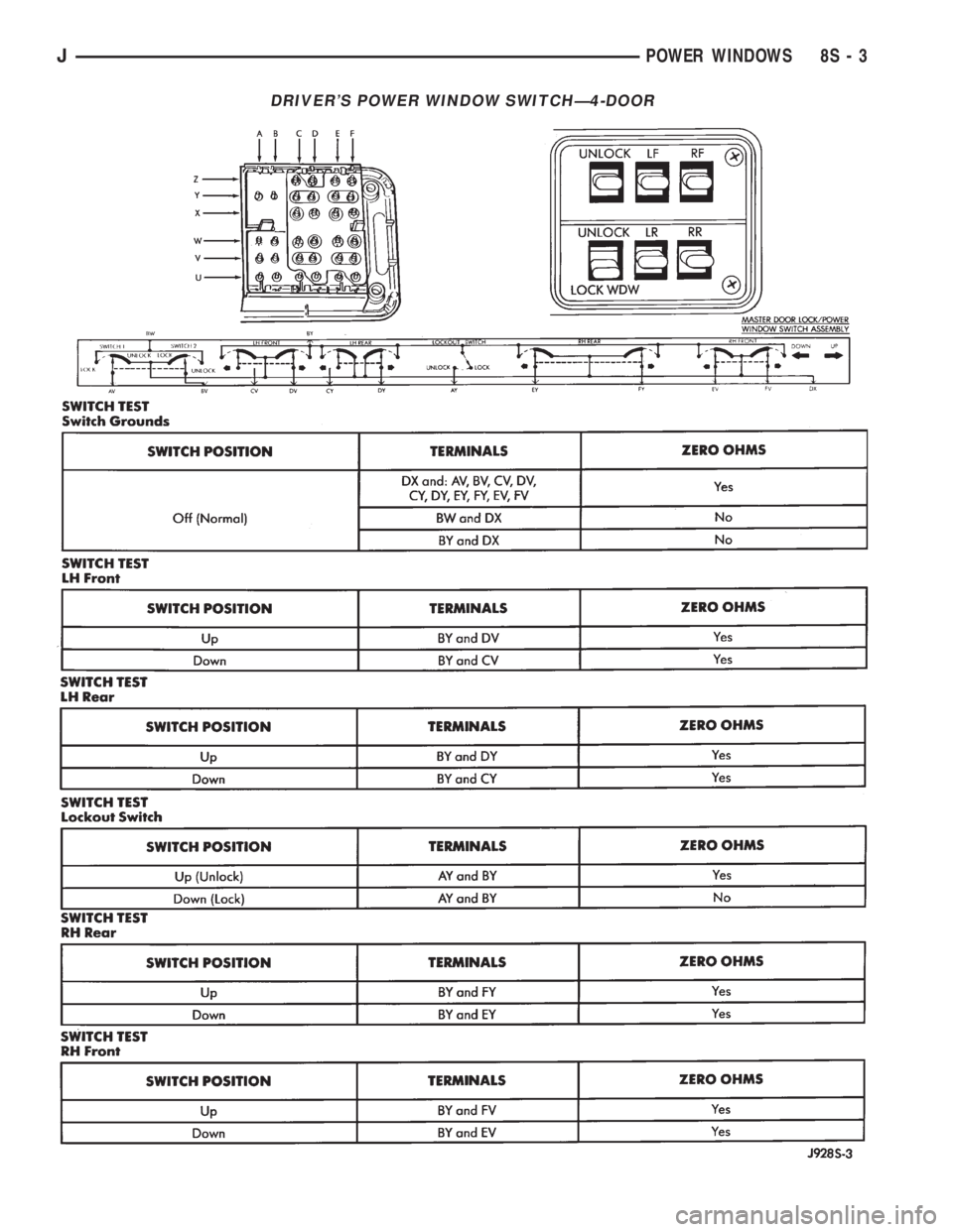
DRIVER'S POWER WINDOW SWITCHÐ4-DOOR
JPOWER WINDOWS 8S - 3
Page 520 of 2158
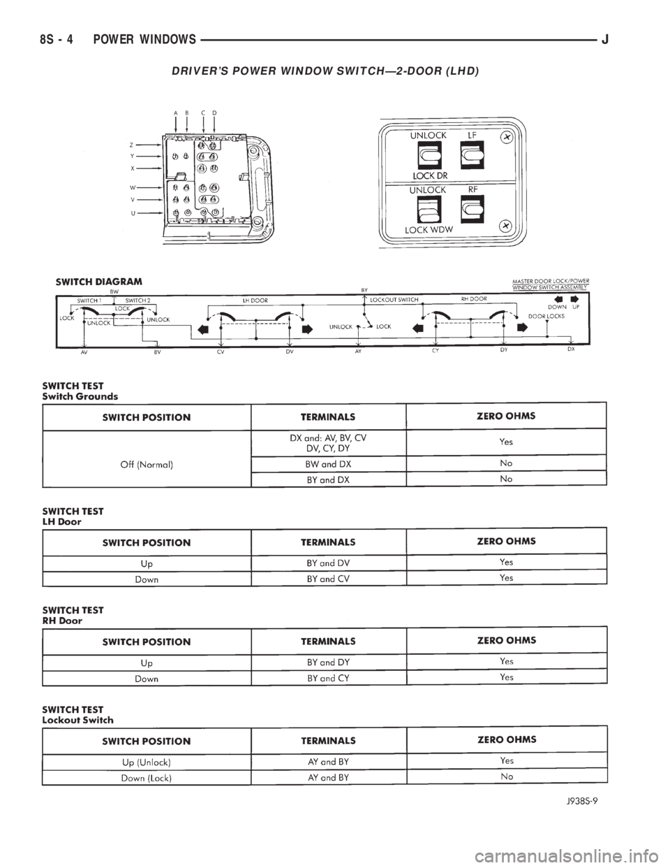
DRIVER'S POWER WINDOW SWITCHÐ2-DOOR (LHD)
8S - 4 POWER WINDOWSJ