1995 JEEP YJ checking oil
[x] Cancel search: checking oilPage 1577 of 2158
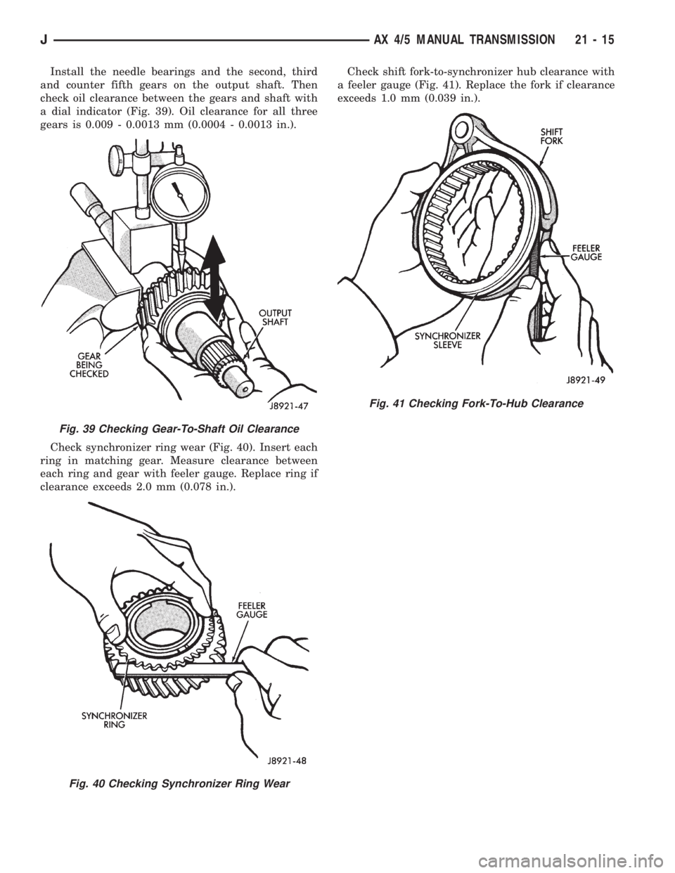
Install the needle bearings and the second, third
and counter fifth gears on the output shaft. Then
check oil clearance between the gears and shaft with
a dial indicator (Fig. 39). Oil clearance for all three
gears is 0.009 - 0.0013 mm (0.0004 - 0.0013 in.).
Check synchronizer ring wear (Fig. 40). Insert each
ring in matching gear. Measure clearance between
each ring and gear with feeler gauge. Replace ring if
clearance exceeds 2.0 mm (0.078 in.).Check shift fork-to-synchronizer hub clearance with
a feeler gauge (Fig. 41). Replace the fork if clearance
exceeds 1.0 mm (0.039 in.).
Fig. 39 Checking Gear-To-Shaft Oil Clearance
Fig. 40 Checking Synchronizer Ring Wear
Fig. 41 Checking Fork-To-Hub Clearance
JAX 4/5 MANUAL TRANSMISSION 21 - 15
Page 1585 of 2158
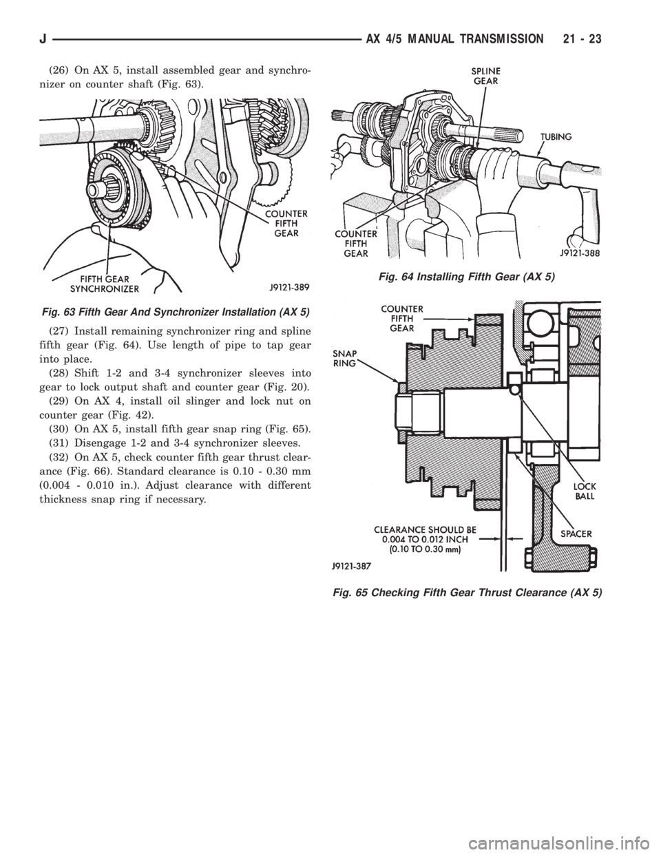
(26) On AX 5, install assembled gear and synchro-
nizer on counter shaft (Fig. 63).
(27) Install remaining synchronizer ring and spline
fifth gear (Fig. 64). Use length of pipe to tap gear
into place.
(28) Shift 1-2 and 3-4 synchronizer sleeves into
gear to lock output shaft and counter gear (Fig. 20).
(29) On AX 4, install oil slinger and lock nut on
counter gear (Fig. 42).
(30) On AX 5, install fifth gear snap ring (Fig. 65).
(31) Disengage 1-2 and 3-4 synchronizer sleeves.
(32) On AX 5, check counter fifth gear thrust clear-
ance (Fig. 66). Standard clearance is 0.10 - 0.30 mm
(0.004 - 0.010 in.). Adjust clearance with different
thickness snap ring if necessary.
Fig. 65 Checking Fifth Gear Thrust Clearance (AX 5)
Fig. 63 Fifth Gear And Synchronizer Installation (AX 5)
Fig. 64 Installing Fifth Gear (AX 5)
JAX 4/5 MANUAL TRANSMISSION 21 - 23
Page 1632 of 2158
30RH/32RH TRANSMISSION DIAGNOSIS
INDEX
page page
Air Pressure Test......................... 74
Analyzing the Road Test.................... 71
Converter Housing Leak Diagnosis............ 75
Converter Stall Test........................ 74
Diagnosis Guides and Charts................ 77
Effects of Incorrect Fluid Level............... 71
Fluid Level Check......................... 70Gearshift Cable/Linkage Adjustment........... 71
General Information....................... 70
Hydraulic Pressure Test.................... 72
Preliminary Diagnosis...................... 70
Road Test............................... 71
Transmission Throttle Valve Cable Adjustment.... 71
GENERAL INFORMATION
Automatic transmission problems are generally a
result of:
²poor engine performance
²incorrect fluid level
²incorrect throttle valve cable adjustment
²incorrect band adjustment
²incorrect hydraulic control pressure adjustments
²hydraulic component malfunctions
²mechanical component malfunctions.
Begin diagnosis by checking the easily accessible
items such as fluid level, fluid condition and control
linkage adjustment. A road test will determine if fur-
ther diagnosis is necessary.
Procedures outlined in this section should be per-
formed in the following sequence to realize the most
accurate results:
²Preliminary diagnosis
²Check fluid level and condition
²Check control linkage Adjustment
²Road test
²Stall test
²Hydraulic pressure test
²Air pressure tests
²Leak test
²Analyze test results and consult diagnosis charts
PRELIMINARY DIAGNOSIS
Two basic procedures are required. One procedure
for vehicles that are driveable and an alternate pro-
cedure for disabled vehicles (will not back up or move
forward).
Vehicle Is Driveable
(1) Check fluid level and condition.
(2) Adjust throttle cable and gearshift linkage if
complaint was based on delayed, erratic, or harsh
shifts.
(3) Road test vehicle and note transmission operat-
ing characteristics.(4) Perform stall test if complaint is based on slug-
gish, low speed acceleration or abnormal throttle
opening needed to maintain normal speeds with
properly tuned engine.
(5) Perform hydraulic pressure tests.
(6) Perform air pressure test to check clutch-band
operation.
Vehicle Is Disabled
(1) Check fluid level and condition.
(2) Check for broken, disconnected throttle linkage.
(3) Check for cracked, leaking cooler lines, or loose,
missing pressure port plugs.
(4) Raise vehicle, start engine, shift transmission
into gear and note following:
(a) If propeller shafts turn but wheels do not,
problem is with differential or axle shafts.
(b) If propeller shafts do not turn and transmis-
sion is noisy, stop engine. Remove oil pan, and
check for debris. If pan is clear, remove transmis-
sion and check for damaged drive plate, converter,
oil pump or input shaft.
(c) If propeller shafts do not turn and transmis-
sion is not noisy, perform hydraulic pressure test to
determine if problem is a hydraulic or mechanical.
FLUID LEVEL CHECK
Transmission fluid level should be checked monthly
under normal operation. If the vehicle is used for
trailer towing or similar heavy load hauling, check
fluid level and condition weekly.
Fluid level is checked with the engine running at
curb idle speed, the transmission in Neutral and the
transmission fluid at normal operating temperature.
FLUID LEVEL CHECK PROCEDURE
(1) Transmission fluid must be at normal operating
temperature for accurate fluid level check. Drive ve-
hicle if necessary to bring fluid temperature up to
normal hot operating temperature of 82ÉC (180ÉF).
(2) Position vehicle on level surface. This is ex-
tremely important for accurate fluid level check.
(3) Start and run engine at curb idle speed.
21 - 70 30RH/32RH TRANSMISSION DIAGNOSISJ
Page 1724 of 2158
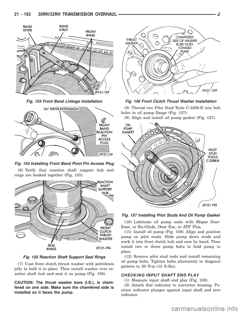
(6) Verify that reaction shaft support hub seal
rings are hooked together (Fig. 155).
(7) Coat front clutch thrust washer with petroleum
jelly to hold it in place. Then install washer over re-
action shaft hub and seat it on pump (Fig. 156).
CAUTION: The thrust washer bore (I.D.), is cham-
fered on one side. Make sure the chamfered side is
installed so it faces the pump.(8) Thread two Pilot Stud Tools C-3288-B into bolt
holes in oil pump flange (Fig. 157).
(9) Align and install oil pump gasket (Fig. 157).
(10) Lubricate oil pump seals with Mopar Door-
Ease, or Ru-Glyde, Door Eze, or ATF Plus.
(11) Install oil pump (Fig. 158). Align and position
pump on pilot studs. Slide pump down studs and
work it into front clutch hub and case by hand. Then
install two or three pump bolts to hold pump in
place.
(12) Remove pilot stud tools and install remaining
oil pump bolts. Tighten bolts alternately in diagonal
pattern to 20 Nzm (15 ft-lbs).
CHECKING INPUT SHAFT END PLAY
(1) Measure input shaft end play (Fig. 159).
(2) Attach dial indicator to converter housing. Po-
sition indicator plunger against input shaft and zero
indicator.
Fig. 153 Front Band Linkage Installation
Fig. 154 Installing Front Band Pivot Pin Access Plug
Fig. 155 Reaction Shaft Support Seal Rings
Fig. 156 Front Clutch Thrust Washer Installation
Fig. 157 Installing Pilot Studs And Oil Pump Gasket
21 - 162 30RH/32RH TRANSMISSION OVERHAULJ
Page 1725 of 2158
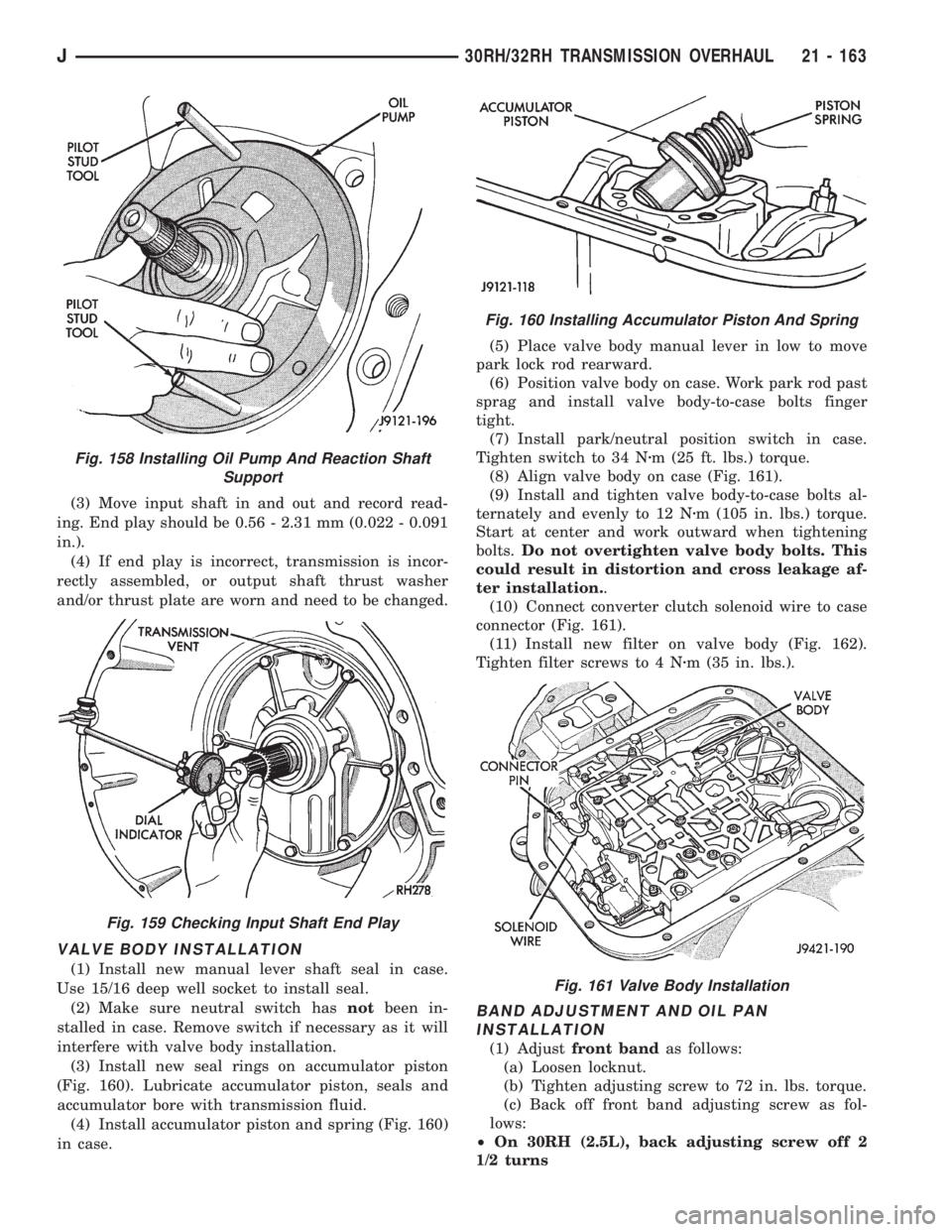
(3) Move input shaft in and out and record read-
ing. End play should be 0.56 - 2.31 mm (0.022 - 0.091
in.).
(4) If end play is incorrect, transmission is incor-
rectly assembled, or output shaft thrust washer
and/or thrust plate are worn and need to be changed.
VALVE BODY INSTALLATION
(1) Install new manual lever shaft seal in case.
Use 15/16 deep well socket to install seal.
(2) Make sure neutral switch hasnotbeen in-
stalled in case. Remove switch if necessary as it will
interfere with valve body installation.
(3) Install new seal rings on accumulator piston
(Fig. 160). Lubricate accumulator piston, seals and
accumulator bore with transmission fluid.
(4) Install accumulator piston and spring (Fig. 160)
in case.(5) Place valve body manual lever in low to move
park lock rod rearward.
(6) Position valve body on case. Work park rod past
sprag and install valve body-to-case bolts finger
tight.
(7) Install park/neutral position switch in case.
Tighten switch to 34 Nzm (25 ft. lbs.) torque.
(8) Align valve body on case (Fig. 161).
(9) Install and tighten valve body-to-case bolts al-
ternately and evenly to 12 Nzm (105 in. lbs.) torque.
Start at center and work outward when tightening
bolts.Do not overtighten valve body bolts. This
could result in distortion and cross leakage af-
ter installation..
(10) Connect converter clutch solenoid wire to case
connector (Fig. 161).
(11) Install new filter on valve body (Fig. 162).
Tighten filter screws to 4 Nzm (35 in. lbs.).
BAND ADJUSTMENT AND OIL PAN
INSTALLATION
(1) Adjustfront bandas follows:
(a) Loosen locknut.
(b) Tighten adjusting screw to 72 in. lbs. torque.
(c) Back off front band adjusting screw as fol-
lows:
²On 30RH (2.5L), back adjusting screw off 2
1/2 turns
Fig. 158 Installing Oil Pump And Reaction Shaft
Support
Fig. 159 Checking Input Shaft End Play
Fig. 160 Installing Accumulator Piston And Spring
Fig. 161 Valve Body Installation
J30RH/32RH TRANSMISSION OVERHAUL 21 - 163
Page 1744 of 2158
AW-4 IN-VEHICLE SERVICE
INDEX
page page
Accumulator Pistons and Springs............. 189
Adapter Housing Seal Replacement........... 191
Checking Fluid Level and Condition........... 182
Manual Valve Shaft Seal Replacement......... 187
Park Interlock Cable Adjustment............. 195
Park Rod and Pawl Service................. 190
Park/Neutral Position Switch................ 183
Refilling After Overhaul or Fluid/Filter Change . . . 182
Second Coast Brake Servo................. 190
Shift Cable Adjustment.................... 195
Speed Sensor........................... 192Speed Sensor RotorÐSpeedometer Drive Gear . . 193
Throttle Position Sensor (TPS) Service........ 193
Transmission Control Module (TCM) Service.... 183
Transmission Cooler Line Fittings............ 197
Transmission Cooler Service................ 196
Transmission Throttle Cable Adjustment........ 194
Transmission Throttle Cable Replacement...... 193
Transmission Valve Body Installation.......... 187
Transmission Valve Body Removal........... 186
Transmission Valve Body Solenoids........... 184
CHECKING FLUID LEVEL AND CONDITION
Recommended fluid for AW-4 transmissions is Mo-
par Dexron IIE/Mercon.
Mopar Dexron II can also be used but only when
Mercon fluid is not available.
CHECKING FLUID LEVEL
(1) Be sure transmission fluid is at normal operat-
ing temperature. Normal operating temperature is
reached after approximately 15 miles (25 km) of op-
eration.
(2) Position vehicle on level surface. This is impor-
tant for an accurate fluid level check.
(3) Shift transmission through all gear ranges and
back to Park.
(4) Apply parking brakes.
(5) Verify that transmission is in Park.
(6) Wipe off dipstick handle to prevent dirt from
entering fill tube. Then remove dipstick and check
fluid level and condition.
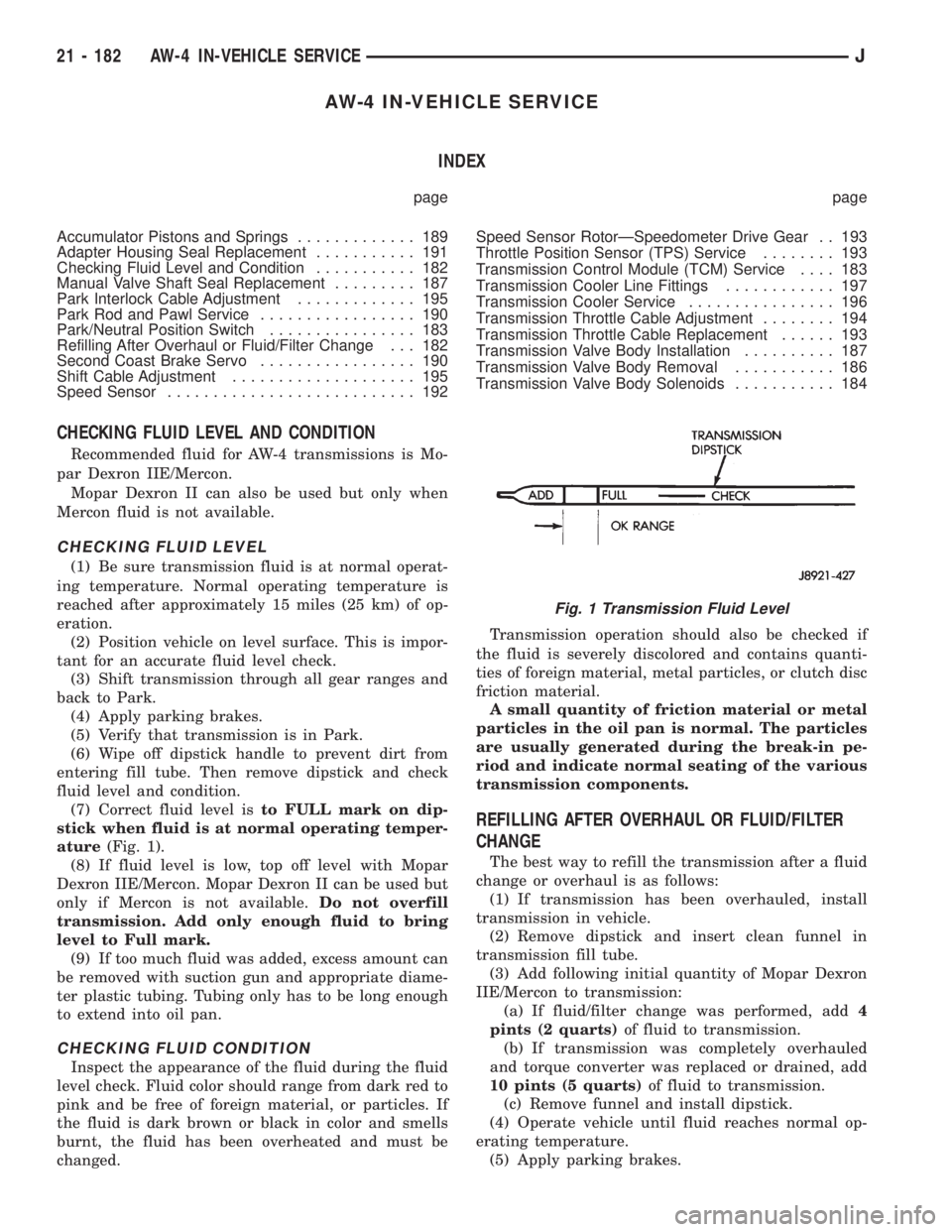
(7) Correct fluid level isto FULL mark on dip-
stick when fluid is at normal operating temper-
ature(Fig. 1).
(8) If fluid level is low, top off level with Mopar
Dexron IIE/Mercon. Mopar Dexron II can be used but
only if Mercon is not available.Do not overfill
transmission. Add only enough fluid to bring
level to Full mark.
(9) If too much fluid was added, excess amount can
be removed with suction gun and appropriate diame-
ter plastic tubing. Tubing only has to be long enough
to extend into oil pan.
CHECKING FLUID CONDITION
Inspect the appearance of the fluid during the fluid
level check. Fluid color should range from dark red to
pink and be free of foreign material, or particles. If
the fluid is dark brown or black in color and smells
burnt, the fluid has been overheated and must be
changed.Transmission operation should also be checked if
the fluid is severely discolored and contains quanti-
ties of foreign material, metal particles, or clutch disc
friction material.
A small quantity of friction material or metal
particles in the oil pan is normal. The particles
are usually generated during the break-in pe-
riod and indicate normal seating of the various
transmission components.
REFILLING AFTER OVERHAUL OR FLUID/FILTER
CHANGE
The best way to refill the transmission after a fluid
change or overhaul is as follows:
(1) If transmission has been overhauled, install
transmission in vehicle.
(2) Remove dipstick and insert clean funnel in
transmission fill tube.
(3) Add following initial quantity of Mopar Dexron
IIE/Mercon to transmission:
(a) If fluid/filter change was performed, add4
pints (2 quarts)of fluid to transmission.
(b) If transmission was completely overhauled
and torque converter was replaced or drained, add
10 pints (5 quarts)of fluid to transmission.
(c) Remove funnel and install dipstick.
(4) Operate vehicle until fluid reaches normal op-
erating temperature.
(5) Apply parking brakes.
Fig. 1 Transmission Fluid Level
21 - 182 AW-4 IN-VEHICLE SERVICEJ
Page 1761 of 2158
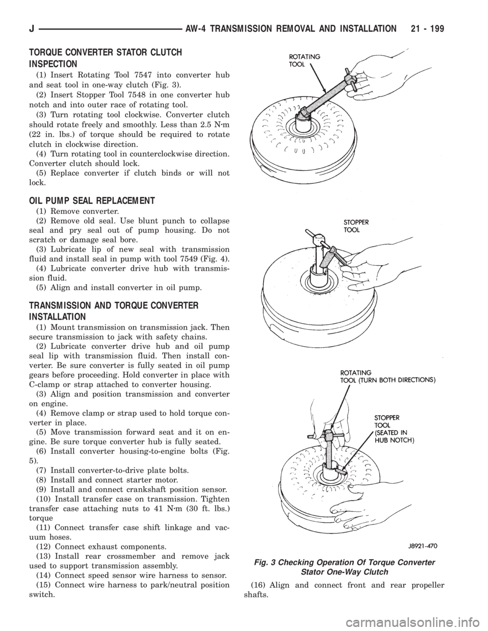
TORQUE CONVERTER STATOR CLUTCH
INSPECTION
(1) Insert Rotating Tool 7547 into converter hub
and seat tool in one-way clutch (Fig. 3).
(2) Insert Stopper Tool 7548 in one converter hub
notch and into outer race of rotating tool.
(3) Turn rotating tool clockwise. Converter clutch
should rotate freely and smoothly. Less than 2.5 Nzm
(22 in. lbs.) of torque should be required to rotate
clutch in clockwise direction.
(4) Turn rotating tool in counterclockwise direction.
Converter clutch should lock.
(5) Replace converter if clutch binds or will not
lock.
OIL PUMP SEAL REPLACEMENT
(1) Remove converter.
(2) Remove old seal. Use blunt punch to collapse
seal and pry seal out of pump housing. Do not
scratch or damage seal bore.
(3) Lubricate lip of new seal with transmission
fluid and install seal in pump with tool 7549 (Fig. 4).
(4) Lubricate converter drive hub with transmis-
sion fluid.
(5) Align and install converter in oil pump.
TRANSMISSION AND TORQUE CONVERTER
INSTALLATION
(1) Mount transmission on transmission jack. Then
secure transmission to jack with safety chains.
(2) Lubricate converter drive hub and oil pump
seal lip with transmission fluid. Then install con-
verter. Be sure converter is fully seated in oil pump
gears before proceeding. Hold converter in place with
C-clamp or strap attached to converter housing.
(3) Align and position transmission and converter
on engine.
(4) Remove clamp or strap used to hold torque con-
verter in place.
(5) Move transmission forward seat and it on en-
gine. Be sure torque converter hub is fully seated.
(6) Install converter housing-to-engine bolts (Fig.
5).
(7) Install converter-to-drive plate bolts.
(8) Install and connect starter motor.
(9) Install and connect crankshaft position sensor.
(10) Install transfer case on transmission. Tighten
transfer case attaching nuts to 41 Nzm (30 ft. lbs.)
torque
(11) Connect transfer case shift linkage and vac-
uum hoses.
(12) Connect exhaust components.
(13) Install rear crossmember and remove jack
used to support transmission assembly.
(14) Connect speed sensor wire harness to sensor.
(15) Connect wire harness to park/neutral position
switch.(16) Align and connect front and rear propeller
shafts.
Fig. 3 Checking Operation Of Torque Converter
Stator One-Way Clutch
JAW-4 TRANSMISSION REMOVAL AND INSTALLATION 21 - 199
Page 1776 of 2158
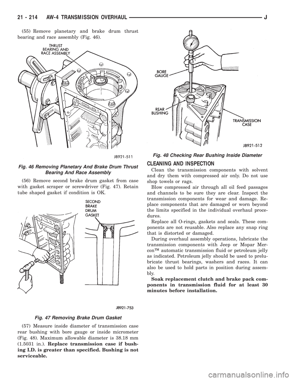
(55) Remove planetary and brake drum thrust
bearing and race assembly (Fig. 46).
(56) Remove second brake drum gasket from case
with gasket scraper or screwdriver (Fig. 47). Retain
tube shaped gasket if condition is OK.
(57) Measure inside diameter of transmission case
rear bushing with bore gauge or inside micrometer
(Fig. 48). Maximum allowable diameter is 38.18 mm
(1.5031 in.).Replace transmission case if bush-
ing I.D. is greater than specified. Bushing is not
serviceable.
CLEANING AND INSPECTION
Clean the transmission components with solvent
and dry them with compressed air only. Do not use
shop towels or rags.
Blow compressed air through all oil feed passages
and channels to be sure they are clear. Inspect the
transmission components for wear and damage. Re-
place components that are damaged or worn beyond
the limits specified in the individual overhaul proce-
dures.
Replace all O-rings, gaskets and seals. These com-
ponents are not reusable. Also replace any snap ring
that is distorted or damaged.
During overhaul assembly operations, lubricate the
transmission components with Jeep or Mopar Mer-
conŸ automatic transmission fluid or petroleum jelly
as indicated. Petroleum jelly should be used to prelu-
bricate thrust bearings, washers and races. It can
also be used to hold parts in position during assem-
bly.
Soak replacement clutch and brake pack com-
ponents in transmission fluid for at least 30
minutes before installation.Fig. 46 Removing Planetary And Brake Drum Thrust
Bearing And Race Assembly
Fig. 47 Removing Brake Drum Gasket
Fig. 48 Checking Rear Bushing Inside Diameter
21 - 214 AW-4 TRANSMISSION OVERHAULJ