1995 JEEP YJ catalytic converter
[x] Cancel search: catalytic converterPage 1377 of 2158
verter. Such conditions can exist when the engine
misfires or otherwise does not operate at peak effi-
ciency.
DO NOT remove spark plug wires from plugs or by
any other means short out cylinders. Failure of the
catalytic converter can occur due to a temperature
increase caused by unburned fuel passing through
the converter.DO NOT allow the engine to operate at fast idle for
extended periods (over 5 minutes). This condition
may result in excessive temperatures in the exhaust
system and on the floor pan.
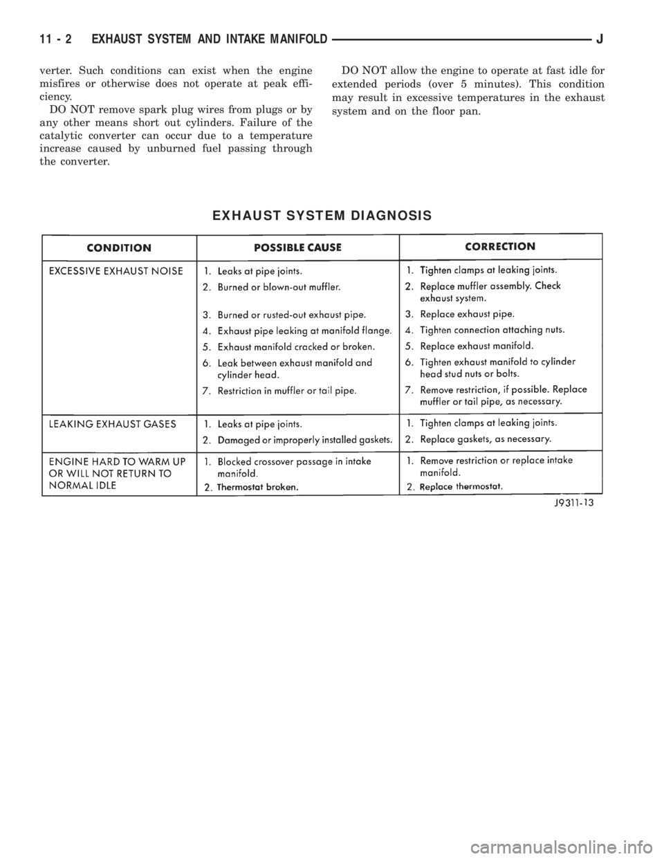
EXHAUST SYSTEM DIAGNOSIS
11 - 2 EXHAUST SYSTEM AND INTAKE MANIFOLDJ
Page 1378 of 2158
SERVICE PROCEDURES
INDEX
page page
Catalytic Converter......................... 4
Engine Exhaust ManifoldÐ2.5L Engine.......... 7
Engine Exhaust ManifoldÐ4.0L Engine.......... 7
Exhaust PipeÐXJ Vehicles................... 3
Exhaust PipeÐYJ Vehicles................... 4Intake ManifoldÐ2.5L Engine................. 7
Intake ManifoldÐ4.0L Engine................. 8
Muffler and Exhaust TailpipeÐXJ Vehicles........ 5
Muffler and Exhaust TailpipeÐYJ Vehicles........ 6
EXHAUST PIPEÐXJ VEHICLES
WARNING: IF TORCHES ARE USED WHEN WORK-
ING ON THE EXHAUST SYSTEM, DO NOT ALLOW
THE FLAME NEAR THE FUEL LINES.
REMOVAL
(1) Raise and support the vehicle.
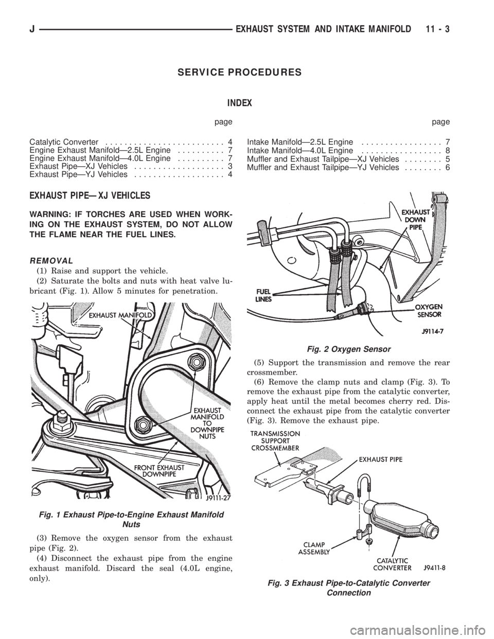
(2) Saturate the bolts and nuts with heat valve lu-
bricant (Fig. 1). Allow 5 minutes for penetration.
(3) Remove the oxygen sensor from the exhaust
pipe (Fig. 2).
(4) Disconnect the exhaust pipe from the engine
exhaust manifold. Discard the seal (4.0L engine,
only).(5) Support the transmission and remove the rear
crossmember.
(6) Remove the clamp nuts and clamp (Fig. 3). To
remove the exhaust pipe from the catalytic converter,
apply heat until the metal becomes cherry red. Dis-
connect the exhaust pipe from the catalytic converter
(Fig. 3). Remove the exhaust pipe.
Fig. 1 Exhaust Pipe-to-Engine Exhaust Manifold
Nuts
Fig. 2 Oxygen Sensor
Fig. 3 Exhaust Pipe-to-Catalytic Converter
Connection
JEXHAUST SYSTEM AND INTAKE MANIFOLD 11 - 3
Page 1379 of 2158
INSTALLATION
(1) Assemble exhaust pipe to manifold and cata-
lytic converter loosely to permit proper alignment of
all parts.
(2) Use a new clamp and tighten the nuts to 61
Nzm (45 ft. lbs.) torque.
(3) Connect the exhaust pipe to the engine exhaust
manifold. Install a new seal between the exhaust
manifold and the exhaust pipe (4.0L engine, only).
Tighten the nuts to 31 Nzm (23 ft. lbs.) torque (Fig.
1).
(3) Install the rear crossmember. Tighten the
crossmember-to-sill bolts to 41 Nzm (30 ft. lbs.)
torque. Remove the support from the transmission.
(4) Coat the oxygen sensor with anti-seize com-
pound. Install the sensor and tighten the nut to 48
Nzm (35 ft. lbs.) torque.
(5) Lower the vehicle.
(6) Start the engine and inspect for exhaust leaks
and exhaust system contact with the body panels.
Adjust the alignment, if needed.
EXHAUST PIPEÐYJ VEHICLES
WARNING: IF TORCHES ARE USED WHEN WORK-
ING ON THE EXHAUST SYSTEM, DO NOT ALLOW
THE FLAME NEAR THE FUEL LINES.
REMOVAL
(1) Raise and support the vehicle.
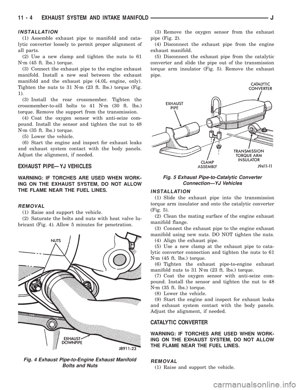
(2) Saturate the bolts and nuts with heat valve lu-
bricant (Fig. 4). Allow 5 minutes for penetration.(3) Remove the oxygen sensor from the exhaust
pipe (Fig. 2).
(4) Disconnect the exhaust pipe from the engine
exhaust manifold.
(5) Disconnect the exhaust pipe from the catalytic
converter and slide the pipe out of the transmission
torque arm insulator (Fig. 5). Remove the exhaust
pipe.
INSTALLATION
(1) Slide the exhaust pipe into the transmission
torque arm insulator and onto the catalytic converter
(Fig. 5).
(2) Clean the mating surface of the engine exhaust
manifold flange.
(3) Connect the exhaust pipe to the engine exhaust
manifold using new nuts. DO NOT tighten the nuts.
(4) Align the exhaust pipe.
(5) Use a new clamp at the exhaust pipe to cata-
lytic converter connection and tighten the nuts to 61
Nzm (45 ft. lbs.) torque.
(6) Tighten the exhaust pipe-to-engine exhaust
manifold nuts to 31 Nzm (23 ft. lbs.) torque.
(7) Coat the oxygen sensor with anti-seize com-
pound. Install the sensor and tighten the nut to 48
Nzm (35 ft. lbs.) torque.
(8) Lower the vehicle.
(9) Start the engine and inspect for exhaust leaks
and exhaust system contact with the body panels.
Adjust the alignment, if needed.
CATALYTIC CONVERTER
WARNING: IF TORCHES ARE USED WHEN WORK-
ING ON THE EXHAUST SYSTEM, DO NOT ALLOW
THE FLAME NEAR THE FUEL LINES.
REMOVAL
(1) Raise and support the vehicle.
Fig. 4 Exhaust Pipe-to-Engine Exhaust Manifold
Bolts and Nuts
Fig. 5 Exhaust Pipe-to-Catalytic Converter
ConnectionÐYJ Vehicles
11 - 4 EXHAUST SYSTEM AND INTAKE MANIFOLDJ
Page 1380 of 2158
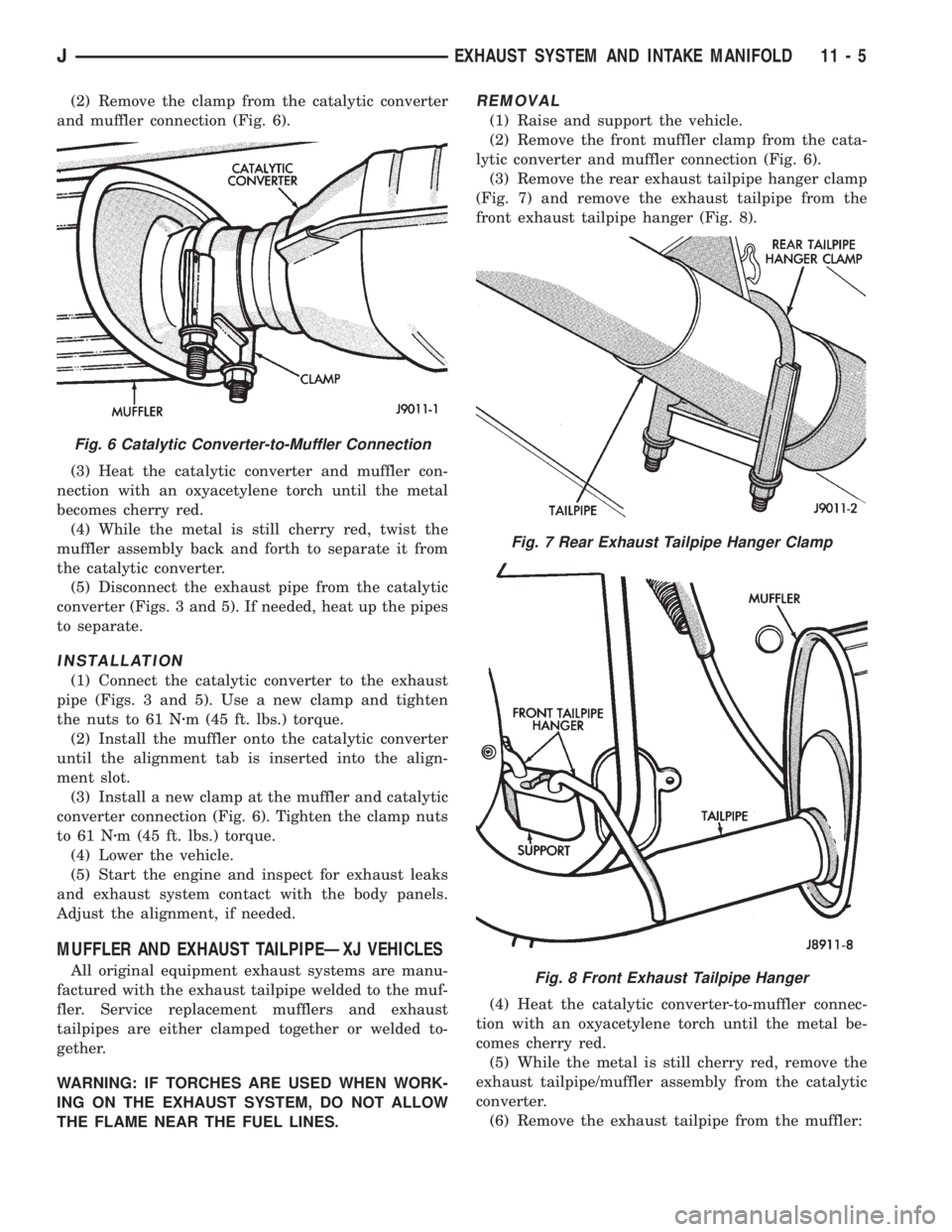
(2) Remove the clamp from the catalytic converter
and muffler connection (Fig. 6).
(3) Heat the catalytic converter and muffler con-
nection with an oxyacetylene torch until the metal
becomes cherry red.
(4) While the metal is still cherry red, twist the
muffler assembly back and forth to separate it from
the catalytic converter.
(5) Disconnect the exhaust pipe from the catalytic
converter (Figs. 3 and 5). If needed, heat up the pipes
to separate.
INSTALLATION
(1) Connect the catalytic converter to the exhaust
pipe (Figs. 3 and 5). Use a new clamp and tighten
the nuts to 61 Nzm (45 ft. lbs.) torque.
(2) Install the muffler onto the catalytic converter
until the alignment tab is inserted into the align-
ment slot.
(3) Install a new clamp at the muffler and catalytic
converter connection (Fig. 6). Tighten the clamp nuts
to 61 Nzm (45 ft. lbs.) torque.
(4) Lower the vehicle.
(5) Start the engine and inspect for exhaust leaks
and exhaust system contact with the body panels.
Adjust the alignment, if needed.
MUFFLER AND EXHAUST TAILPIPEÐXJ VEHICLES
All original equipment exhaust systems are manu-
factured with the exhaust tailpipe welded to the muf-
fler. Service replacement mufflers and exhaust
tailpipes are either clamped together or welded to-
gether.
WARNING: IF TORCHES ARE USED WHEN WORK-
ING ON THE EXHAUST SYSTEM, DO NOT ALLOW
THE FLAME NEAR THE FUEL LINES.
REMOVAL
(1) Raise and support the vehicle.
(2) Remove the front muffler clamp from the cata-
lytic converter and muffler connection (Fig. 6).
(3) Remove the rear exhaust tailpipe hanger clamp
(Fig. 7) and remove the exhaust tailpipe from the
front exhaust tailpipe hanger (Fig. 8).
(4) Heat the catalytic converter-to-muffler connec-
tion with an oxyacetylene torch until the metal be-
comes cherry red.
(5) While the metal is still cherry red, remove the
exhaust tailpipe/muffler assembly from the catalytic
converter.
(6) Remove the exhaust tailpipe from the muffler:
Fig. 6 Catalytic Converter-to-Muffler Connection
Fig. 7 Rear Exhaust Tailpipe Hanger Clamp
Fig. 8 Front Exhaust Tailpipe Hanger
JEXHAUST SYSTEM AND INTAKE MANIFOLD 11 - 5
Page 1381 of 2158
²To remove an original equipment exhaust tailpipe/
muffler combination, cut the exhaust tailpipe close to
the muffler. Collapse the part remaining in the muf-
fler and remove.
²To remove a service exhaust tailpipe/muffler com-
bination, apply heat until the metal becomes cherry
red. Remove the exhaust tailpipe/muffler clamp and
twist the exhaust tailpipe out of the muffler.
INSTALLATION
(1) Install the muffler onto the catalytic converter.
Install the clamp and tighten the nuts finger tight.
(2) Install the exhaust tailpipe into the rear of the
muffler.
(3) Install the exhaust tailpipe/muffler assembly on
the rear exhaust tailpipe hanger. Make sure that the
exhaust tailpipe has sufficient clearance from the
floor pan.
(4) Install the remaining clamps and the front ex-
haust tailpipe hanger.
(5) Tighten the nuts on the muffler-to-catalytic
converter clamp to 61 Nzm (45 ft. lbs.) torque (Fig. 6).
Tighten the nuts on the rear exhaust tailpipe clamp
to 14 Nzm (10 ft. lbs.) torque (Fig. 7).
(6) Lower the vehicle.
(7) Start the engine and inspect for exhaust leaks
and exhaust system contact with the body panels.
Adjust the alignment, if needed.
MUFFLER AND EXHAUST TAILPIPEÐYJ VEHICLES
All original equipment exhaust systems are manu-
factured with the exhaust tailpipe welded to the muf-
fler. Service replacement mufflers and exhaust
tailpipes are clamped together.
WARNING: IF TORCHES ARE USED WHEN WORK-
ING ON THE EXHAUST SYSTEM, DO NOT ALLOW
THE FLAME NEAR THE FUEL LINES.
REMOVAL
(1) Raise the vehicle and support the rear of the
vehicle by the side rails and allow the axle to hang
free.
(2) Remove the front muffler clamp from the cata-
lytic converter and muffler connection (Fig. 6).
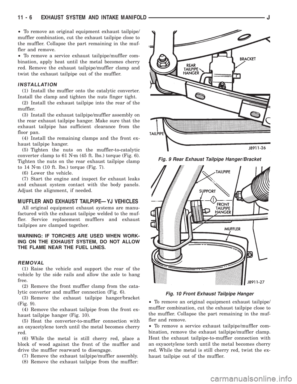
(3) Remove the exhaust tailpipe hanger/bracket
(Fig. 9).
(4) Remove the exhaust tailpipe from the front ex-
haust tailpipe hanger (Fig. 10).
(5) Heat the converter-to-muffler connection with
an oxyacetylene torch until the metal becomes cherry
red.
(6) While the metal is still cherry red, place a
block of wood against the front of the muffler and
drive the muffler rearward to disengage.
(7) Remove the exhaust tailpipe/muffler assembly.
(8) Remove the exhaust tailpipe from the muffler:²To remove an original equipment exhaust tailpipe/
muffler combination, cut the exhaust tailpipe close to
the muffler. Collapse the part remaining in the muf-
fler and remove.
²To remove a service exhaust tailpipe/muffler com-
bination, remove the exhaust tailpipe/muffler clamp.
Heat the exhaust tailpipe-to-muffler connection with
an oxyacetylene torch until the metal becomes cherry
red. While the metal is still cherry red, twist the ex-
haust tailpipe out of the muffler.
Fig. 9 Rear Exhaust Tailpipe Hanger/Bracket
Fig. 10 Front Exhaust Tailpipe Hanger
11 - 6 EXHAUST SYSTEM AND INTAKE MANIFOLDJ
Page 1382 of 2158
INSTALLATION
(1) Install the muffler onto the catalytic converter
outlet. Ensure that the locator on the converter
aligns with the notch on the muffler, if so equipped.
Install the clamp and tighten the nuts finger tight.
(2) Install the exhaust tailpipe into the muffler
outlet. Ensure that the locator on the exhaust
tailpipe aligns with the notch on the muffler, if so
equipped. Install the clamp and tighten the nuts fin-
ger tight.
(3) Install the front exhaust tailpipe supports and
the rear exhaust tailpipe hanger. Ensure that the ex-
haust tailpipe has sufficient clearance from the floor
pan and shields.
(4) Tighten the nuts on the muffler-to-catalytic
converter and the muffler-to-exhaust tailpipe clamps
to 61 Nzm (45 ft. lbs.) torque.
(5) Lower the vehicle.
(6) Start the engine and inspect for exhaust leaks
and contact with the body panels and shields.
ENGINE EXHAUST MANIFOLDÐ2.5L ENGINE
REMOVAL
(1) Disconnect the battery negative cable.
(2) Remove all components attached to the intake
manifold.
(3) Raise the vehicle.
(4) Disconnect the exhaust pipe from the engine
exhaust manifold.
(5) Lower the vehicle.
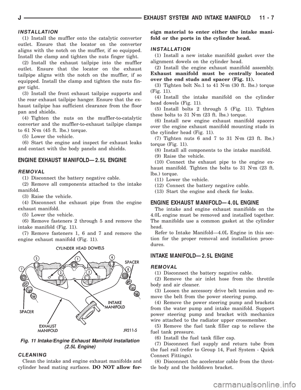
(6) Remove fasteners 2 through 5 and remove the
intake manifold (Fig. 11).
(7) Remove fasteners 1, 6 and 7 and remove the
engine exhaust manifold (Fig. 11).
CLEANING
Clean the intake and engine exhaust manifolds and
cylinder head mating surfaces.DO NOT allow for-eign material to enter either the intake mani-
fold or the ports in the cylinder head.
INSTALLATION
(1) Install a new intake manifold gasket over the
alignment dowels on the cylinder head.
(2) Install the engine exhaust manifold assembly.
Exhaust manifold must be centrally located
over the end studs and spacer (Fig. 11).
(3) Tighten bolt No.1 to 41 Nzm (30 ft. lbs.) torque
(Fig. 11).
(4) Install the intake manifold on the cylinder
head dowels (Fig. 11).
(5) Install bolts 2 through 5 (Fig. 11). Tighten
these bolts to 31 Nzm (23 ft. lbs.) torque.
(6) Install new engine exhaust manifold spacers
over the engine exhaust manifold mounting studs in
the cylinder head (Fig. 11).
(7) Tighten nuts 6 and 7 to 31 Nzm (23 ft. lbs.)
torque (Fig. 11).
(8) Install all components to the intake manifold.
(9) Raise the vehicle.
(10) Connect the exhaust pipe to the engine ex-
haust manifold. Tighten the bolts to 31 Nzm (23 ft.
lbs.) torque.
(11) Lower the vehicle.
(12) Connect the battery negative cable.
(13) Start the engine and check for leaks.
ENGINE EXHAUST MANIFOLDÐ4.0L ENGINE
The intake and engine exhaust manifolds on the
4.0L engine must be removed and installed together.
The manifolds use a common gasket at the cylinder
head.
Refer to Intake ManifoldÐ4.0L Engine in this sec-
tion for the proper removal and installation proce-
dures.
INTAKE MANIFOLDÐ2.5L ENGINE
REMOVAL
(1) Disconnect the battery negative cable.
(2) Remove the air inlet hose from the throttle
body and air cleaner.
(3) Loosen the accessory drive belt tension and re-
move the belt from the power steering pump.
(4) Remove the power steering pump and brackets
from the water pump and intake manifold. Support
power steering pump and bracket with mechanics
wire attached to the radiator upper crossmember.
(5) Remove the fuel tank filler cap to relieve the
fuel tank pressure.
(6) Install the fuel tank filler cap.
(7) Disconnect fuel supply and return tube from
the fuel rail (refer to Group 14, Fuel System - Quick
Connect Fittings).
(8) Disconnect the accelerator cable from the throt-
tle body and the holddown bracket.
Fig. 11 Intake/Engine Exhaust Manifold Installation
(2.5L Engine)
JEXHAUST SYSTEM AND INTAKE MANIFOLD 11 - 7
Page 1495 of 2158
POWER STEERING PUMP
INDEX
page page
Drive Pulley Replacement................... 13
Flow Control Valve Fitting O-Ring Seal......... 14
Power Steering PumpÐInitial Operation........ 15
Pressure and Return Hose Replacement........ 11Pump Replacement........................ 12
Reservoir Replacement..................... 14
Service Information........................ 11
SERVICE INFORMATION
The power steering pump internal components are
not serviced or adjusted. If a malfunction or an inter-
nal fluid leak occurs, the complete unit must be re-
placed. A reservoir, cap, and O-ring seal kit are the
only service components available.
PRESSURE AND RETURN HOSE REPLACEMENT
Cap hose open ends and pump/steering gear fit-
tings to prevent entry of foreign material.
WARNING: POWER STEERING FLUID (AND PUMP
COMPONENTS) AND THE EXHAUST SYSTEM CAN
BE EXTREMELY HOT IF THE ENGINE HAS BEEN
RECENTLY OPERATING. DO NOT START THE EN-
GINE WITH ANY LOOSE OR DISCONNECTED
HOSES. DO NOT ALLOW THE HOSES TO TOUCH A
HOT EXHAUST MANIFOLD OR THE CATALYTIC
CONVERTER.
REMOVAL
(1) Remove fasteners from hose retaining brackets
at all locations.
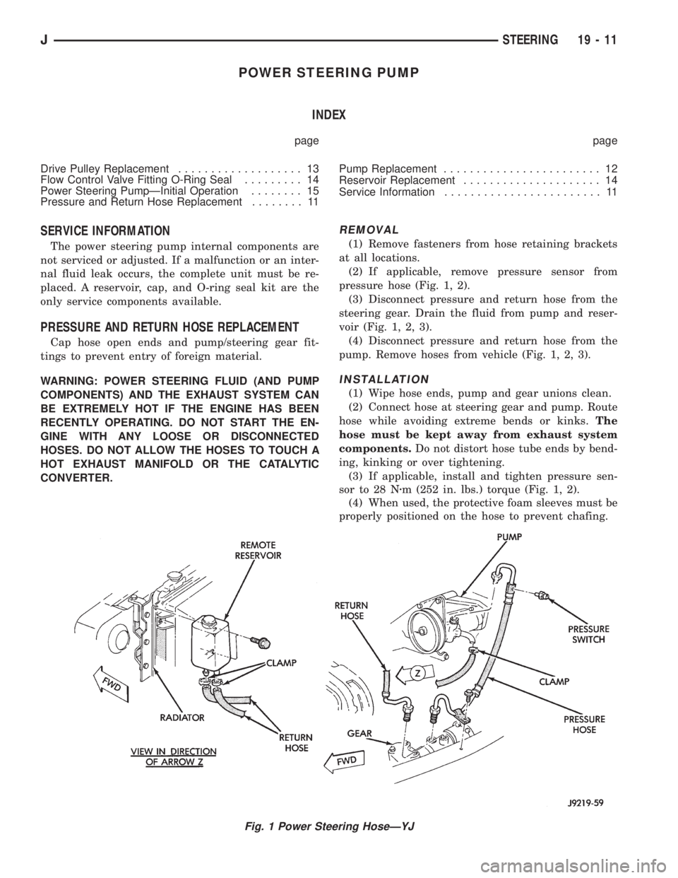
(2) If applicable, remove pressure sensor from
pressure hose (Fig. 1, 2).
(3) Disconnect pressure and return hose from the
steering gear. Drain the fluid from pump and reser-
voir (Fig. 1, 2, 3).
(4) Disconnect pressure and return hose from the
pump. Remove hoses from vehicle (Fig. 1, 2, 3).
INSTALLATION
(1) Wipe hose ends, pump and gear unions clean.
(2) Connect hose at steering gear and pump. Route
hose while avoiding extreme bends or kinks.The
hose must be kept away from exhaust system
components.Do not distort hose tube ends by bend-
ing, kinking or over tightening.
(3) If applicable, install and tighten pressure sen-
sor to 28 Nzm (252 in. lbs.) torque (Fig. 1, 2).
(4) When used, the protective foam sleeves must be
properly positioned on the hose to prevent chafing.
Fig. 1 Power Steering HoseÐYJ
JSTEERING 19 - 11
Page 1680 of 2158
(12) Install transfer case on transmission. Tighten
attaching nuts to 47 Nzm (35 ft. lbs.) torque if case
has 3/8 studs, or 35 Nzm (26 ft. lbs.) if case has 5/16
studs.
(13) Install rear crossmember and attach transmis-
sion rear support to crossmember.
(14) Remove transmission jack.
(15) Connect vehicle speed sensor wires.
(16) Install inspection cover on converter housing.(17) Install exhaust pipes and support brackets, if
removed.
(18) Install starter motor.
(19) Connect wires to park/neutral position switch.
(20) Connect gearshift and linkage and throttle ca-
ble.
(21) Connect transfer case shift linkage.
(22) Connect propeller shafts to transfer case
yokes.
(23) Connect front exhaust pipes and catalytic con-
verter support bracket bolts (if removed).
(24) Install skid plate, rear cushion and bracket, if
removed.
(25) Fill transfer case to bottom edge of fill plug
hole with Mopar Dexron II.
(26) Lower vehicle and fill transmission to correct
level with ATF Plus, type 7176 fluid.
(27) Install fan shroud and bolts (if removed).
(28) Check and adjust gearshift cable or linkage if
necessary. Then check and adjust throttle valve cable
if necessary.
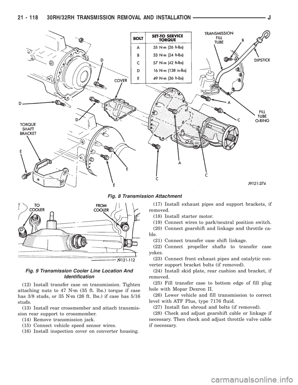
Fig. 8 Transmission Attachment
Fig. 9 Transmission Cooler Line Location And
Identification
21 - 118 30RH/32RH TRANSMISSION REMOVAL AND INSTALLATIONJ