1995 JEEP YJ check oil
[x] Cancel search: check oilPage 1818 of 2158
UPPER BODY DISASSEMBLY AND
INSPECTION
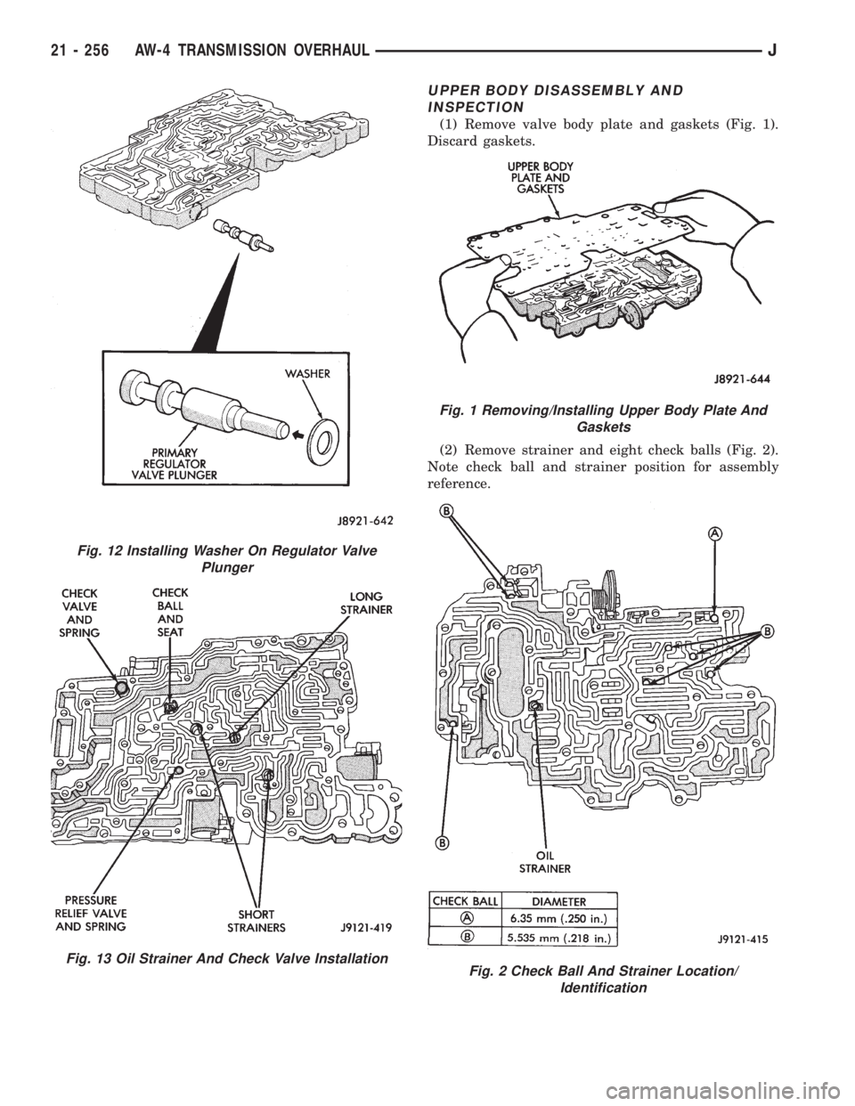
(1) Remove valve body plate and gaskets (Fig. 1).
Discard gaskets.
(2) Remove strainer and eight check balls (Fig. 2).
Note check ball and strainer position for assembly
reference.
Fig. 12 Installing Washer On Regulator Valve
Plunger
Fig. 13 Oil Strainer And Check Valve Installation
Fig. 1 Removing/Installing Upper Body Plate And
Gaskets
Fig. 2 Check Ball And Strainer Location/
Identification
21 - 256 AW-4 TRANSMISSION OVERHAULJ
Page 1823 of 2158
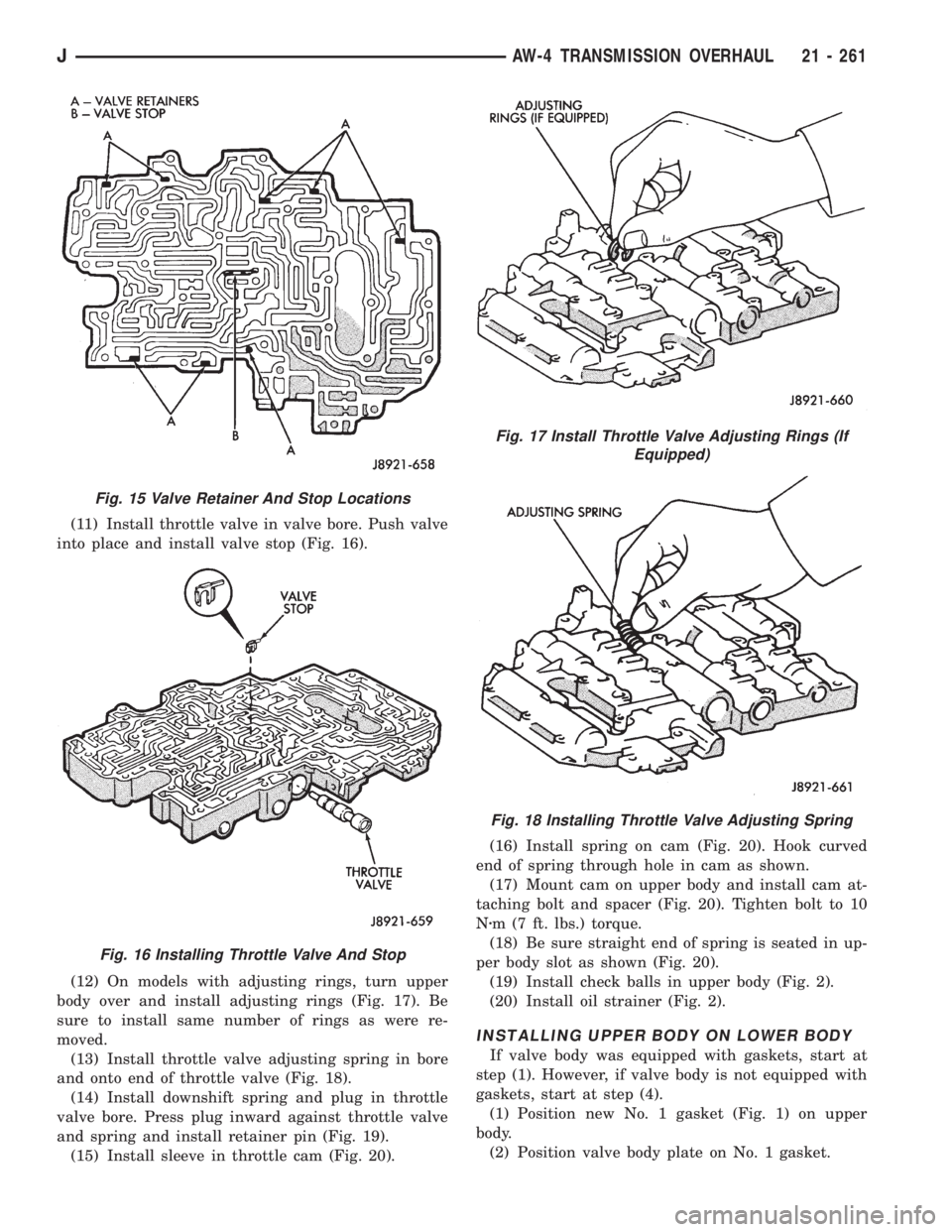
(11) Install throttle valve in valve bore. Push valve
into place and install valve stop (Fig. 16).
(12) On models with adjusting rings, turn upper
body over and install adjusting rings (Fig. 17). Be
sure to install same number of rings as were re-
moved.
(13) Install throttle valve adjusting spring in bore
and onto end of throttle valve (Fig. 18).
(14) Install downshift spring and plug in throttle
valve bore. Press plug inward against throttle valve
and spring and install retainer pin (Fig. 19).
(15) Install sleeve in throttle cam (Fig. 20).(16) Install spring on cam (Fig. 20). Hook curved
end of spring through hole in cam as shown.
(17) Mount cam on upper body and install cam at-
taching bolt and spacer (Fig. 20). Tighten bolt to 10
Nzm (7 ft. lbs.) torque.
(18) Be sure straight end of spring is seated in up-
per body slot as shown (Fig. 20).
(19) Install check balls in upper body (Fig. 2).
(20) Install oil strainer (Fig. 2).
INSTALLING UPPER BODY ON LOWER BODY
If valve body was equipped with gaskets, start at
step (1). However, if valve body is not equipped with
gaskets, start at step (4).
(1) Position new No. 1 gasket (Fig. 1) on upper
body.
(2) Position valve body plate on No. 1 gasket.
Fig. 15 Valve Retainer And Stop Locations
Fig. 16 Installing Throttle Valve And Stop
Fig. 17 Install Throttle Valve Adjusting Rings (If
Equipped)
Fig. 18 Installing Throttle Valve Adjusting Spring
JAW-4 TRANSMISSION OVERHAUL 21 - 261
Page 1840 of 2158
(69) Verify input shaft rotation. Shaft should rotate
smoothly and not bind.
(70) Lubricate and install new O-ring on transmis-
sion throttle cable adapter and install cable in case
(Fig. 55).
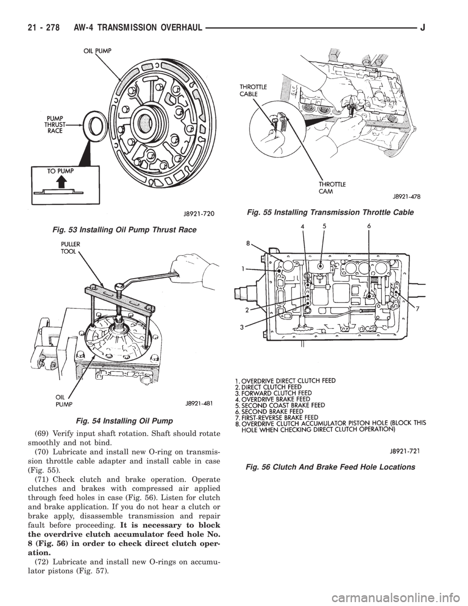
(71) Check clutch and brake operation. Operate
clutches and brakes with compressed air applied
through feed holes in case (Fig. 56). Listen for clutch
and brake application. If you do not hear a clutch or
brake apply, disassemble transmission and repair
fault before proceeding.It is necessary to block
the overdrive clutch accumulator feed hole No.
8 (Fig. 56) in order to check direct clutch oper-
ation.
(72) Lubricate and install new O-rings on accumu-
lator pistons (Fig. 57).
Fig. 53 Installing Oil Pump Thrust Race
Fig. 54 Installing Oil Pump
Fig. 55 Installing Transmission Throttle Cable
Fig. 56 Clutch And Brake Feed Hole Locations
21 - 278 AW-4 TRANSMISSION OVERHAULJ
Page 1841 of 2158
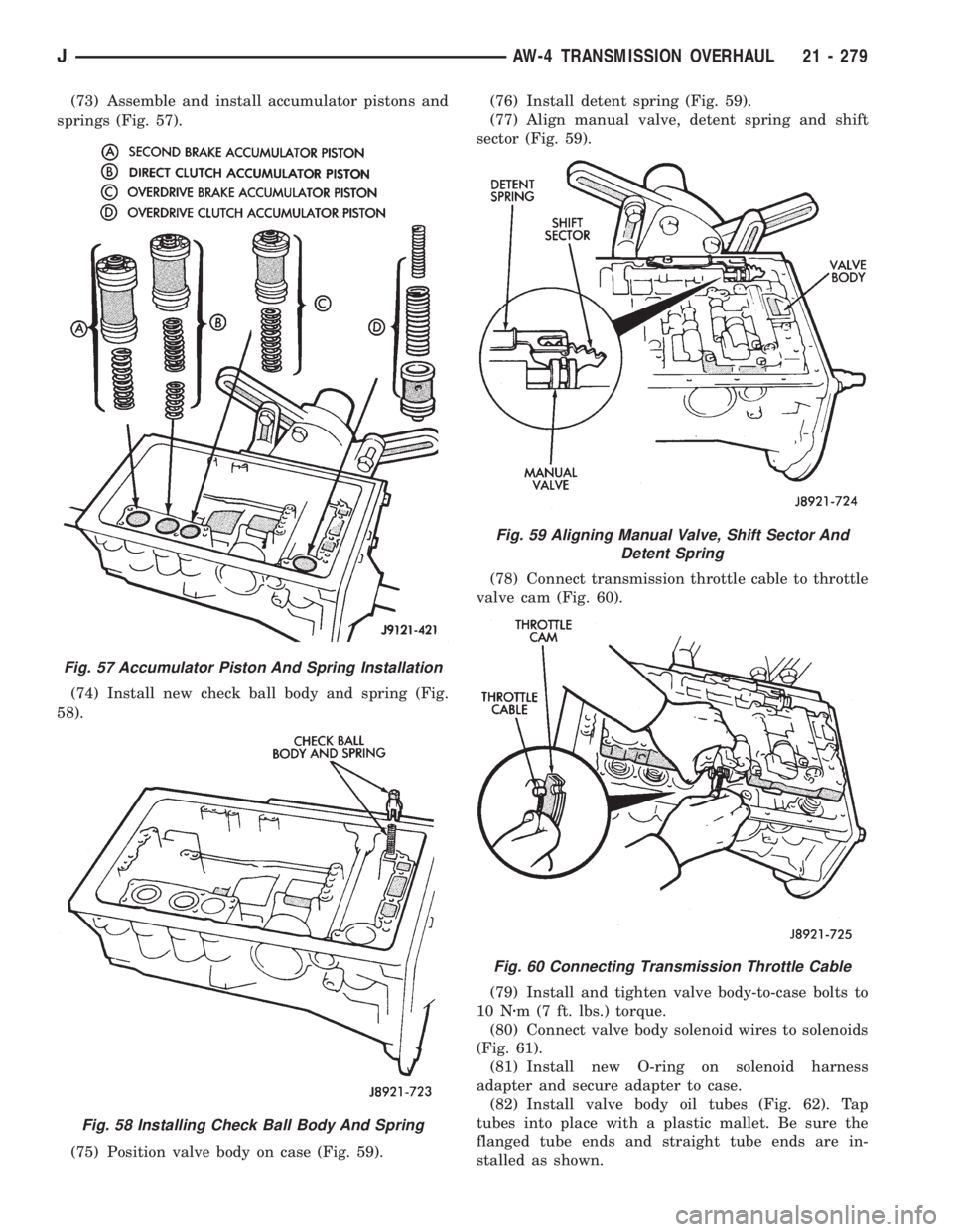
(73) Assemble and install accumulator pistons and
springs (Fig. 57).
(74) Install new check ball body and spring (Fig.
58).
(75) Position valve body on case (Fig. 59).(76) Install detent spring (Fig. 59).
(77) Align manual valve, detent spring and shift
sector (Fig. 59).
(78) Connect transmission throttle cable to throttle
valve cam (Fig. 60).
(79) Install and tighten valve body-to-case bolts to
10 Nzm (7 ft. lbs.) torque.
(80) Connect valve body solenoid wires to solenoids
(Fig. 61).
(81) Install new O-ring on solenoid harness
adapter and secure adapter to case.
(82) Install valve body oil tubes (Fig. 62). Tap
tubes into place with a plastic mallet. Be sure the
flanged tube ends and straight tube ends are in-
stalled as shown.
Fig. 57 Accumulator Piston And Spring Installation
Fig. 58 Installing Check Ball Body And Spring
Fig. 59 Aligning Manual Valve, Shift Sector And
Detent Spring
Fig. 60 Connecting Transmission Throttle Cable
JAW-4 TRANSMISSION OVERHAUL 21 - 279
Page 1856 of 2158
OVERHAUL CLEANING AND INSPECTION
Clean the transfer case components thoroughly
with solvent. Remove all traces of sealer from the
case and retainer seal surfaces.
Clean the oil pickup screen with solvent. Shake ex-
cess solvent from screen and allow it air dry. Use
compressed air to remove solvent residue from all oil
feed passages and channels in the case halves.
Inspect the splines and bearing surfaces on the
both shafts. Replace either shaft as necessary if wear,
or damage is evident.
Check condition of the shift forks, fork pads and
shift rail. Minor scratches/nicks on the rail can be
smoothed with 320/400 grit emery cloth. Replace the
mode fork pads if worn. Replace the range fork if the
pads are worn, missing, or damaged.
On synchro equipped models, inspect the synchro
sleeve, hub, struts, springs, and the stop ring. Re-
place worn, or damaged parts as necessary.
Do not attempt to salvage and reuse snap rings
that were bent, or distorted. It is recommended that
all snap rings be replaced during overhaul.Replace the front yoke nut as it should not be re-
used. Also replace the rubber seal if worn, cut, or
torn.
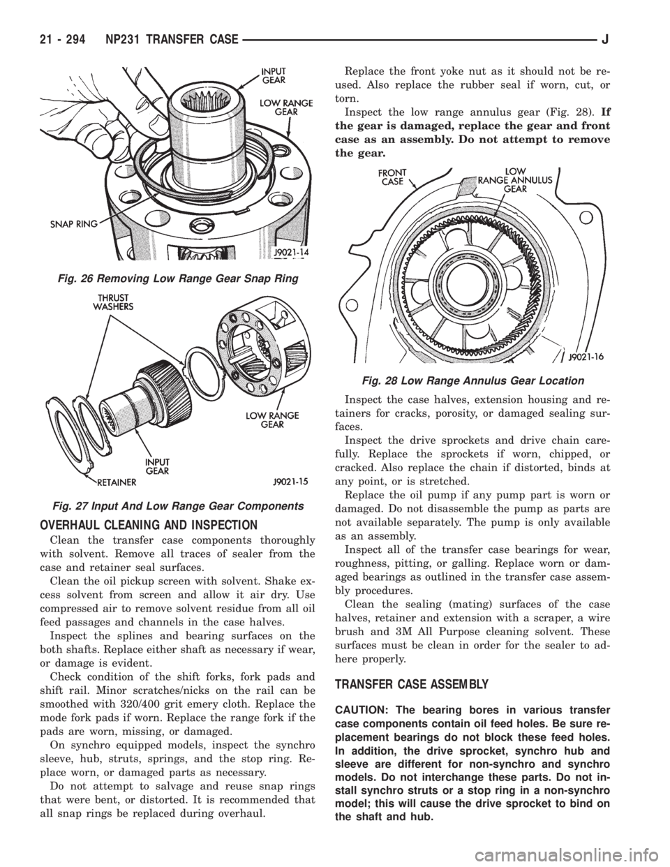
Inspect the low range annulus gear (Fig. 28).If
the gear is damaged, replace the gear and front
case as an assembly. Do not attempt to remove
the gear.
Inspect the case halves, extension housing and re-
tainers for cracks, porosity, or damaged sealing sur-
faces.
Inspect the drive sprockets and drive chain care-
fully. Replace the sprockets if worn, chipped, or
cracked. Also replace the chain if distorted, binds at
any point, or is stretched.
Replace the oil pump if any pump part is worn or
damaged. Do not disassemble the pump as parts are
not available separately. The pump is only available
as an assembly.
Inspect all of the transfer case bearings for wear,
roughness, pitting, or galling. Replace worn or dam-
aged bearings as outlined in the transfer case assem-
bly procedures.
Clean the sealing (mating) surfaces of the case
halves, retainer and extension with a scraper, a wire
brush and 3M All Purpose cleaning solvent. These
surfaces must be clean in order for the sealer to ad-
here properly.
TRANSFER CASE ASSEMBLY
CAUTION: The bearing bores in various transfer
case components contain oil feed holes. Be sure re-
placement bearings do not block these feed holes.
In addition, the drive sprocket, synchro hub and
sleeve are different for non-synchro and synchro
models. Do not interchange these parts. Do not in-
stall synchro struts or a stop ring in a non-synchro
model; this will cause the drive sprocket to bind on
the shaft and hub.
Fig. 26 Removing Low Range Gear Snap Ring
Fig. 27 Input And Low Range Gear Components
Fig. 28 Low Range Annulus Gear Location
21 - 294 NP231 TRANSFER CASEJ
Page 1881 of 2158
Inspect the differential gears, thrust washers and
case halves. Replace the mainshaft gear if the gear
teeth or the brass ring on the underside of the gear
are damaged. Replace the differential as an assembly
if the gears, case halves, or the pins in the lower case
half are damaged.
Inspect the case halves, extension housing and re-
tainers for cracks, porosity, or damaged sealing sur-
faces. Inspect the shafts, gears, chain and shift
components for wear or damage.
Inspect all of the transfer case bearings for wear,
roughness, pitting, or galling. Replace worn or dam-
aged bearings as outlined in the assembly section.
TRANSFER CASE ASSEMBLY
(1) Lubricate transfer case components with auto-
matic transmission fluid or petroleum jelly (where in-
dicated) during assembly.
CAUTION: The bearing bores in various transfer
case components contain oil feed holes. Be sure re-
placement bearings do not block these feed holes.
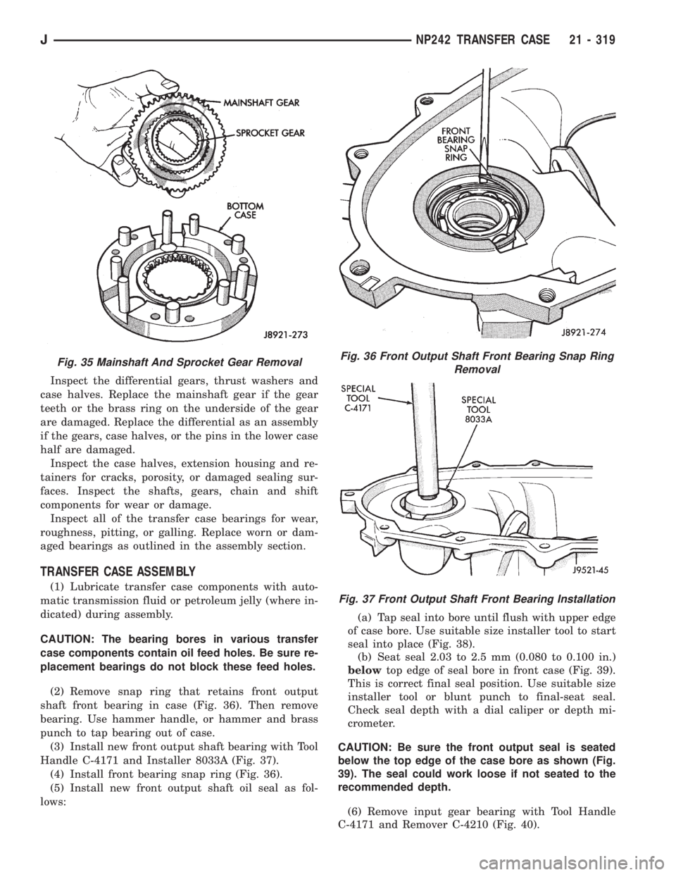
(2) Remove snap ring that retains front output
shaft front bearing in case (Fig. 36). Then remove
bearing. Use hammer handle, or hammer and brass
punch to tap bearing out of case.
(3) Install new front output shaft bearing with Tool
Handle C-4171 and Installer 8033A (Fig. 37).
(4) Install front bearing snap ring (Fig. 36).
(5) Install new front output shaft oil seal as fol-
lows:(a) Tap seal into bore until flush with upper edge
of case bore. Use suitable size installer tool to start
seal into place (Fig. 38).
(b) Seat seal 2.03 to 2.5 mm (0.080 to 0.100 in.)
belowtop edge of seal bore in front case (Fig. 39).
This is correct final seal position. Use suitable size
installer tool or blunt punch to final-seat seal.
Check seal depth with a dial caliper or depth mi-
crometer.
CAUTION: Be sure the front output seal is seated
below the top edge of the case bore as shown (Fig.
39). The seal could work loose if not seated to the
recommended depth.
(6) Remove input gear bearing with Tool Handle
C-4171 and Remover C-4210 (Fig. 40).
Fig. 35 Mainshaft And Sprocket Gear RemovalFig. 36 Front Output Shaft Front Bearing Snap Ring
Removal
Fig. 37 Front Output Shaft Front Bearing Installation
JNP242 TRANSFER CASE 21 - 319
Page 1908 of 2158
TIRE CHAINS
Tire snow chains may be used on certain models.
Refer to Owner's Manual for more information.
CLEANING OF TIRES
Steam cleaning may be used for cleaning.
DO NOT use gasoline or wire brush for cleaning.
DO NOT use mineral oil or an oil-based solvent.
PRESSURE GAUGES
High-quality, dial-type, air-pressure gauges are rec-
ommended. After checking with the gauge, replace
valve cap and finger tight.
TIRE INFLATION PRESSURES
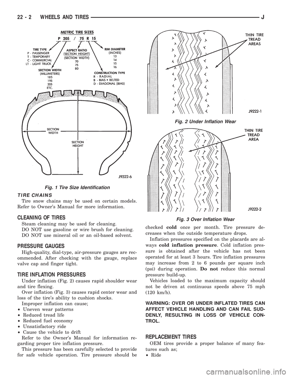
Under inflation (Fig. 2) causes rapid shoulder wear
and tire flexing.
Over inflation (Fig. 3) causes rapid center wear and
loss of the tire's ability to cushion shocks.
Improper inflation can cause;
²Uneven wear patterns
²Reduced tread life
²Reduced fuel economy
²Unsatisfactory ride
²Cause the vehicle to drift
Refer to the Owner's Manual for information re-
garding proper tire inflation pressure.
This pressure has been carefully selected to provide
for safe vehicle operation. Tire pressure should becheckedcoldonce per month. Tire pressure de-
creases when the outside temperature drops.
Inflation pressures specified on the placards are al-
wayscold inflation pressure. Cold inflation pres-
sure is obtained after the vehicle has not been
operated for at least 3 hours. Tire inflation pressures
may increase from 2 to 6 pounds per square inch
(psi) during operation.Do notreduce this normal
pressure build-up.
Vehicles loaded to the maximum capacity should
not be driven at continuous speeds above 75 mph
(120 km/h).
WARNING: OVER OR UNDER INFLATED TIRES CAN
AFFECT VEHICLE HANDLING AND CAN FAIL SUD-
DENLY, RESULTING IN LOSS OF VEHICLE CON-
TROL.
REPLACEMENT TIRES
OEM tires provide a proper balance of many fea-
tures such as;
²Ride
Fig. 1 Tire Size Identification
Fig. 2 Under Inflation Wear
Fig. 3 Over Inflation Wear
22 - 2 WHEELS AND TIRESJ
Page 2091 of 2158
REFRIGERANT SERVICE AND PERFORMANCE TEST
INDEX
page page
Air Conditioning Performance Tests............ 12
Charging Refrigerant System................. 11
Evacuating Refrigerant System............... 11Leak Testing Refrigerant.................... 11
Recovering Refrigerant System............... 11
Refrigerant Oil........................... 12
LEAK TESTING REFRIGERANT
REVIEW WARNINGS AND CAUTIONS IN
THIS GROUP BEFORE LEAK TESTING.
If A/C system is not cooling properly, determine if
system is fully charged. Refer to Refrigerant System
Diagnosis Chart. If the system is empty evacuate the
A/C system and charge system with 0.283 kPa (0.6
lbs. or 10 oz.) R-134a refrigerant. Refer to Charging
Refrigerant System for instructions. To detect a leak
in the system, perform the following procedures.
(1) Position the vehicle in a wind free work area.
This will aid in detecting small leaks.
(2) Bring A/C system up to operating temperature
and pressure. This is done by allowing the engine to
run with the A/C on for 5 to 7 minutes.
(3) Open hood 5 minutes prior to leak test. This
will dissipate any accumulated refrigerant in the en-
gine compartment.
(4) With the engine not running, use an R-134a
Electronic Leak Detector and search for leaks. Move
probe slowly along the bottom side of lines and fit-
tings, because R-134a is heavier than air. Fittings,
lines, or components that appear to be oily usually
indicates a refrigerant leak.
(5) To inspect the evaporator core for leaks. Set the
blower at low speed and the selector in PANEL and
RECIRC mode check for leaks at CENTER panel out-
lets.
RECOVERING REFRIGERANT SYSTEM
REVIEW WARNINGS AND CAUTIONS IN
GENERAL INFORMATION SECTION OF THIS
GROUP BEFORE DISCHARGING SYSTEM.
R-134a refrigerant is a hydrofluorocarbon (HFC)
that does not contain chlorine. R-134a refrigerant Re-
covery/Recycling Station that meets SAE standard
J2210 must be used to recover the refrigerant. Refer
to the operating instructions provided with the equip-
ment for proper operation.
EVACUATING REFRIGERANT SYSTEM
REVIEW WARNINGS AND CAUTIONS IN
GENERAL INFORMATION SECTION OF THIS
GROUP BEFORE EVACUATING SYSTEM.
If the A/C system has been open to the atmosphere,
it must be evacuated before the system can be
charged. Moisture and air mixed with refrigerant will
raise the compressor head pressure above acceptable
operating levels. This will reduce the performance of
the air conditioner and damage the compressor. Mois-
ture will boil at near room temperature when ex-
posed to vacuum. To evacuate the refrigerant system
use following procedure:
(1) Connect a suitable charging station and mani-
fold gauge set to the vehicle.
(2) Open the low and high side valves and start
vacuum pump. When suction gauge reads 88 kPa (26
in. Hg) vacuum or greater, close all valves and turn
off vacuum pump. If system fails to reach specified
vacuum, the system has a leak that must be cor-
rected. If system maintains the specified vacuum for
30 minutes, start the vacuum pump. Then open the
suction and discharge valves and evacuate an addi-
tional 10 minutes.
(3) Close all valves. Turn off and disconnect the
vacuum pump.
The system is now ready to be charged with refrig-
erant.
CHARGING REFRIGERANT SYSTEM
REVIEW WARNINGS AND CAUTIONS IN
GENERAL INFORMATION SECTION OF THIS
GROUP BEFORE CHARGING SYSTEM.
After the system has been tested for leaks and
evacuated, a refrigerant charge can be injected into
the system. Refer to refrigerant capacities for proper
amount of refrigerant charge. Charge the system us-
ing a Recovery/Recycling/Charging Station approved
for R-134a refrigerant. Refer to the instructions pro-
vided with the equipment for proper operation.
REFRIGERANT CHARGE CAPACITY
The R-134a system charge capacity is 0.9 kPa (32
oz.) for XJ and YJ vehicles.
JHEATING AND AIR CONDITIONING 24 - 11