1995 JEEP YJ check oil
[x] Cancel search: check oilPage 1437 of 2158
MULTI-PORT FUEL INJECTION (MFI)ÐGENERAL DIAGNOSIS
INDEX
page page
Automatic Shutdown (ASD) Relay Testing....... 46
Camshaft Position Sensor Test............... 46
Crankshaft Position Sensor Test.............. 47
Diagnostic Trouble Code (DTC)............... 54
DRB Scan Tool........................... 54
Engine Coolant Temperature Sensor Test....... 46
Extended Idle Switch Test................... 48
Fuel Injector Test......................... 51
Fuel Pump Relay Testing................... 47
Fuel System Pressure Test.................. 51
General Information....................... 35
Idle Air Control Motor Test................... 49
Intake Manifold Air Temperature Sensor Test..... 46Manifold Absolute Pressure (Map) Sensor Test . . . 47
On-Board Diagnostics (OBD)................. 51
Oxygen Sensor (O2S) Heating Element Test..... 48
Pcm System Schematics.................... 41
Powertrain Control Module (PCM) 60-Way
Connector............................. 40
RelaysÐOperation/Testing.................. 50
Starter Motor Relay Test.................... 51
Throttle Position Sensor (TPS) Test............ 48
Torque Converter Clutch Relay Test............ 48
Vehicle Speed Sensor Test.................. 48
Visual Inspection.......................... 35
GENERAL INFORMATION
All 2.5L 4-cylinder and 4.0L 6-cylinder engines are
equipped with sequential Multi-Port Fuel Injection
(MFI). The MFI system provides precise air/fuel ra-
tios for all driving conditions.
VISUAL INSPECTION
A visual inspection for loose, disconnected, or incor-
rectly routed wires and hoses should be made. This
should be done before attempting to diagnose or ser-
vice the fuel injection system. A visual check will
help spot these faults and save unnecessary test and
diagnostic time. A thorough visual inspection will in-
clude the following checks:
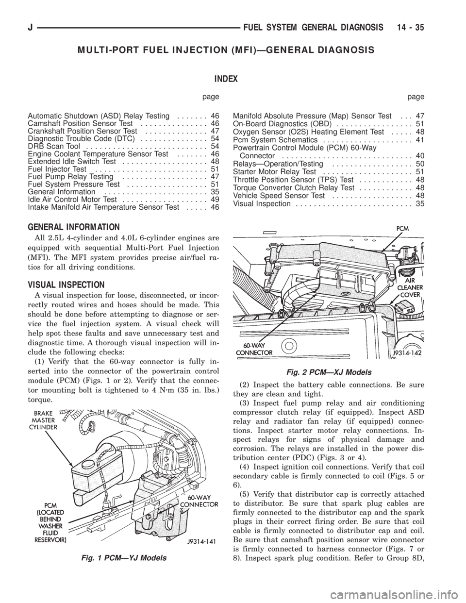
(1) Verify that the 60-way connector is fully in-
serted into the connector of the powertrain control
module (PCM) (Figs. 1 or 2). Verify that the connec-
tor mounting bolt is tightened to 4 Nzm (35 in. lbs.)
torque.(2) Inspect the battery cable connections. Be sure
they are clean and tight.
(3) Inspect fuel pump relay and air conditioning
compressor clutch relay (if equipped). Inspect ASD
relay and radiator fan relay (if equipped) connec-
tions. Inspect starter motor relay connections. In-
spect relays for signs of physical damage and
corrosion. The relays are installed in the power dis-
tribution center (PDC) (Figs. 3 or 4).
(4) Inspect ignition coil connections. Verify that coil
secondary cable is firmly connected to coil (Figs. 5 or
6).
(5) Verify that distributor cap is correctly attached
to distributor. Be sure that spark plug cables are
firmly connected to the distributor cap and the spark
plugs in their correct firing order. Be sure that coil
cable is firmly connected to distributor cap and coil.
Be sure that camshaft position sensor wire connector
is firmly connected to harness connector (Figs. 7 or
8). Inspect spark plug condition. Refer to Group 8D,
Fig. 1 PCMÐYJ Models
Fig. 2 PCMÐXJ Models
JFUEL SYSTEM GENERAL DIAGNOSIS 14 - 35
Page 1455 of 2158
line. However, these could result in a rich or lean
condition causing an oxygen sensor DTC to be stored
in the PCM.
Secondary Ignition Circuit:The PCM cannot
detect an inoperative ignition coil, fouled or worn
spark plugs, ignition cross firing, or open circuited
spark plug cables.
Engine Timing:The PCM cannot detect an incor-
rectly indexed timing chain, camshaft sprocket or
crankshaft sprocket. The PCM also cannot detect an
incorrectly indexed distributor. However, these could
result in a rich or lean condition causing an oxygen
sensor DTC to be stored in the PCM.
Cylinder Compression:The PCM cannot detect
uneven, low, or high engine cylinder compression.
Exhaust System:The PCM cannot detect a
plugged, restricted or leaking exhaust system.
Fuel Injector Malfunctions:The PCM cannot de-
termine if the fuel injector is clogged, or the wrong
injector is installed. However, these could result in a
rich or lean condition causing an oxygen sensor DTC
to be stored in the PCM.
Excessive Oil Consumption:Although the PCM
monitors exhaust stream oxygen content through ox-
ygen sensor (closed loop), it cannot determine exces-
sive oil consumption.
Throttle Body Air Flow:The PCM cannot detect
a clogged or restricted air cleaner inlet or air cleaner
element.
Evaporative System:The PCM will not detect a
restricted, plugged or loaded EVAP canister.
Vacuum Assist:Leaks or restrictions in the vac-
uum circuits of vacuum assisted engine control sys-
tem devices are not monitored by the PCM. However,
a vacuum leak at the MAP sensor will be monitored
and a diagnostic trouble code (DTC) will be gener-
ated by the PCM.
Powertrain Control Module (PCM) System
Ground:The PCM cannot determine a poor system
ground. However, a DTC may be generated as a re-
sult of this condition.
Powertrain Control Module (PCM) Connector
Engagement:The PCM cannot determine spread or
damaged connector pins. However, a DTC may be
generated as a result of this condition.
HIGH AND LOW LIMITS
The powertrain control module (PCM) compares in-
put signal voltages from each input device. It will es-
tablish high and low limits that are programmed into
it for that device. If the input voltage is not within
specifications and other Diagnostic Trouble Code
(DTC) criteria are met, a DTC will be stored in mem-
ory. Other DTC criteria might include engine rpm
limits or input voltages from other sensors or
switches. The other inputs might have to be sensed
by the PCM when it senses a high or low input volt-
age from the control system device in question.
ACCESSING DIAGNOSTIC TROUBLE CODES
A stored diagnostic trouble code (DTC) can be dis-
played by cycling the ignition key On-Off-On-Off-On
within three seconds and observing the malfunction
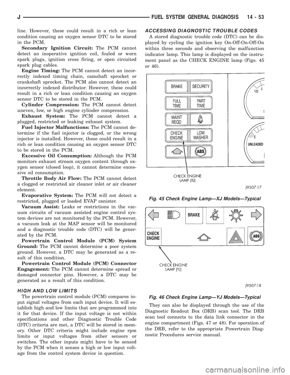
indicator lamp. This lamp is displayed on the instru-
ment panel as the CHECK ENGINE lamp (Figs. 45
or 46).
They can also be displayed through the use of the
Diagnostic Readout Box (DRB) scan tool. The DRB
scan tool connects to the data link connector in the
engine compartment (Figs. 47 or 48). For operation of
the DRB, refer to the appropriate Powertrain Diag-
nostic Procedures service manual.
Fig. 45 Check Engine LampÐXJ ModelsÐTypical
Fig. 46 Check Engine LampÐYJ ModelsÐTypical
JFUEL SYSTEM GENERAL DIAGNOSIS 14 - 53
Page 1464 of 2158
FUEL RAIL ASSEMBLY
REMOVAL
WARNING: THE FUEL SYSTEM IS UNDER CON-
STANT FUEL PRESSURE (EVEN WITH THE ENGINE
OFF) OF APPROXIMATELY 131-269 KPA (19-39 PSI).
THIS PRESSURE MUST BE RELEASED BEFORE
SERVICING THE FUEL RAIL.
(1) Remove fuel tank filler tube cap.
(2) Disconnect the negative battery cable from bat-
tery.
(3) Perform the Fuel System Pressure Release Pro-
cedure as described in the Fuel Delivery System sec-
tion of this Group.
(4) Remove and numerically attach a tag (if fuel
injector is not already tagged), the injector harness
connectors. Do this at each injector (Fig. 12).
(5) Disconnect vacuum line from fuel pressure reg-
ulator (Fig. 12).
(6) Disconnect fuel supply line from fuel rail and
the fuel return line from fuel pressure regulator (Fig.
12). Refer to Fuel Tubes/Lines/Hoses and Clamps, or
Quick-Connect Fittings. These can both be found in
the Fuel Delivery section of this group.
(7) Remove fuel rail mounting bolts.
On models with automatic transmissions, it may be
necessary to remove automatic transmission throttle
line pressure cable and bracket. This will aid in fuel
rail assembly removal.
(8) Remove fuel rail by gently rocking until all the
fuel injectors are out of the intake manifold.
INSTALLATION
(1) Position tips of all fuel injectors into the corre-
sponding injector bore in the intake manifold. Seat
injectors into manifold.
(2) Tighten fuel rail mounting bolts to 27 Nzm (20
ft. lbs.) torque.
(3) Connect injector harness connectors to appro-
priate (tagged) injector.
(4) Connect both fuel lines to fuel rail. Refer to the
Fuel Delivery section of this group for procedures.
(5) Connect vacuum supply line to fuel pressure
regulator.
(6) Install protective cap to pressure test port fit-
ting.
(7) Install fuel tank cap.
(8) Connect negative battery cable to battery.
(9) Start engine and check for fuel leaks.
FUEL SYSTEM PRESSURE RELEASE PROCEDURE
WARNING: THE FUEL SYSTEM IS UNDER A CON-
STANT PRESSURE (EVEN WITH THE ENGINE OFF)
OF APPROXIMATELY 100 KPA (14.5 PSI). BEFORE
SERVICING THE FUEL PUMP, FUEL RAIL, FUELLINES, FUEL FILTER OR FUEL INJECTOR, THE
FUEL SYSTEM PRESSURE MUST BE RELEASED.
Refer to the Fuel Delivery System section of this
group. See Fuel Pressure Release procedure.
FUEL TANKS
Refer to the Fuel Tank section of this group for re-
moval/installation procedures.
FUEL TANK PRESSURE RELIEF/ROLLOVER VALVE
Refer to the Fuel Tank section of this group for re-
moval/installation procedures.
FUEL TUBES/LINES/HOSES AND CLAMPS
Refer to the Fuel Delivery System section of this
group for removal/installation procedures. Also refer
to Quick-Connect Fittings in the Fuel Delivery sec-
tion of this group.
IDLE AIR CONTROL (IAC) MOTOR
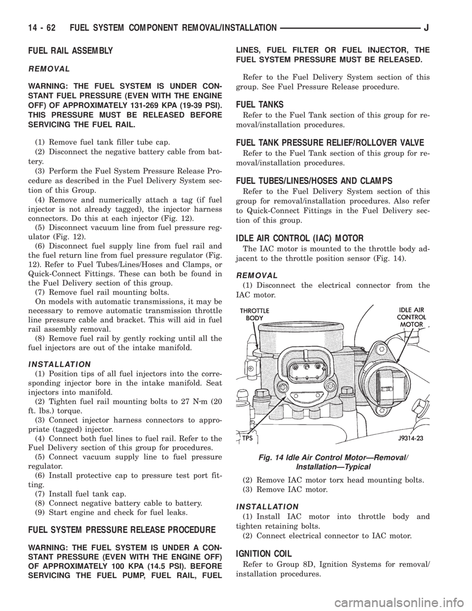
The IAC motor is mounted to the throttle body ad-
jacent to the throttle position sensor (Fig. 14).
REMOVAL
(1) Disconnect the electrical connector from the
IAC motor.
(2) Remove IAC motor torx head mounting bolts.
(3) Remove IAC motor.
INSTALLATION
(1) Install IAC motor into throttle body and
tighten retaining bolts.
(2) Connect electrical connector to IAC motor.
IGNITION COIL
Refer to Group 8D, Ignition Systems for removal/
installation procedures.
Fig. 14 Idle Air Control MotorÐRemoval/
InstallationÐTypical
14 - 62 FUEL SYSTEM COMPONENT REMOVAL/INSTALLATIONJ
Page 1500 of 2158
STEERING LINKAGEÐXJ
INDEX
page page
Drag Link............................... 16
Pitman Arm.............................. 17
Service Information........................ 16Steering Damper.......................... 17
TieRod ................................ 16
SERVICE INFORMATION
The steering linkage consists of a pitman arm, drag
link, tie rod, and steering damper. Adjustment
sleeves are used on the tie rod and drag link for toe
and steering wheel alignment.
Refer to Group 2, Front Suspension and Axle for
additional information.
The tie-rod end ball stud seals should be inspected
during all oil changes.
A damaged ball stud seal requires removal of the
seal. Inspect the tie-rod end ball stud at the throat
opening. Check for lubricant loss, contamination, ball
stud wear or corrosion. If these conditions exist, re-
place the tie-rod. A replacement seal can be installed
if lubricant is in good condition. Otherwise, a com-
plete replacement ball stud end should be installed.
Lubricate the tie-rod end with MOPARtMulti-Mile-
age Lubricant, or equivalent product.
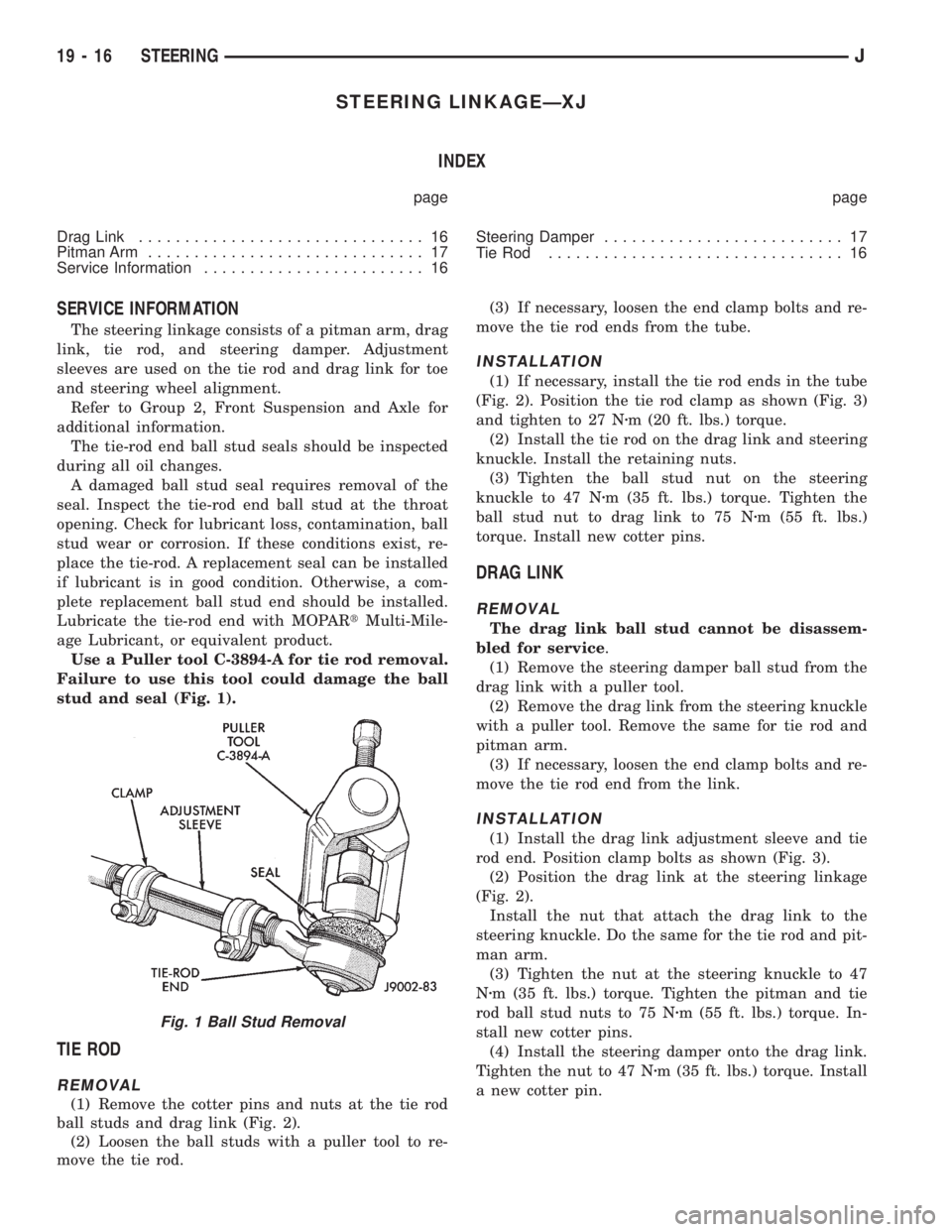
Use a Puller tool C-3894-A for tie rod removal.
Failure to use this tool could damage the ball
stud and seal (Fig. 1).
TIE ROD
REMOVAL
(1) Remove the cotter pins and nuts at the tie rod
ball studs and drag link (Fig. 2).
(2) Loosen the ball studs with a puller tool to re-
move the tie rod.(3) If necessary, loosen the end clamp bolts and re-
move the tie rod ends from the tube.
INSTALLATION
(1) If necessary, install the tie rod ends in the tube
(Fig. 2). Position the tie rod clamp as shown (Fig. 3)
and tighten to 27 Nzm (20 ft. lbs.) torque.
(2) Install the tie rod on the drag link and steering
knuckle. Install the retaining nuts.
(3) Tighten the ball stud nut on the steering
knuckle to 47 Nzm (35 ft. lbs.) torque. Tighten the
ball stud nut to drag link to 75 Nzm (55 ft. lbs.)
torque. Install new cotter pins.
DRAG LINK
REMOVAL
The drag link ball stud cannot be disassem-
bled for service.
(1) Remove the steering damper ball stud from the
drag link with a puller tool.
(2) Remove the drag link from the steering knuckle
with a puller tool. Remove the same for tie rod and
pitman arm.
(3) If necessary, loosen the end clamp bolts and re-
move the tie rod end from the link.
INSTALLATION
(1) Install the drag link adjustment sleeve and tie
rod end. Position clamp bolts as shown (Fig. 3).
(2) Position the drag link at the steering linkage
(Fig. 2).
Install the nut that attach the drag link to the
steering knuckle. Do the same for the tie rod and pit-
man arm.
(3) Tighten the nut at the steering knuckle to 47
Nzm (35 ft. lbs.) torque. Tighten the pitman and tie
rod ball stud nuts to 75 Nzm (55 ft. lbs.) torque. In-
stall new cotter pins.
(4) Install the steering damper onto the drag link.
Tighten the nut to 47 Nzm (35 ft. lbs.) torque. Install
a new cotter pin.
Fig. 1 Ball Stud Removal
19 - 16 STEERINGJ
Page 1503 of 2158
STEERING LINKAGEÐYJ
INDEX
page page
Drag Link............................... 20
Pitman Arm.............................. 20
Service Information........................ 19Steering Damper.......................... 20
TieRod ................................ 19
SERVICE INFORMATION
The steering linkage consists of a pitman arm, drag
link, tie rod, and steering damper. Adjustment
sleeves are used on the tie rod and drag link for toe
and steering wheel alignment.
Refer to Group 2, Front Suspension and Axle for
additional information.The tie-rod end ball stud seals should be inspected
during all oil changes.
A damaged ball stud seal requires removal of the
seal. Inspect the tie-rod end ball stud at the throat
opening. Check for lubricant loss, contamination, ball
stud wear or corrosion. If these conditions exist, re-
place the tie-rod. A replacement seal can be installed
if lubricant is in good condition. Otherwise, a com-
plete replacement ball stud end should be installed.
Lubricate the tie-rod end with MOPARtMulti-Mile-
age Lubricant, or equivalent product.
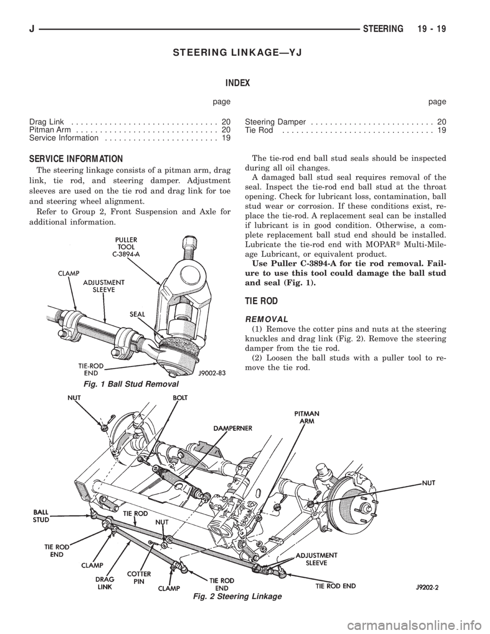
Use Puller C-3894-A for tie rod removal. Fail-
ure to use this tool could damage the ball stud
and seal (Fig. 1).
TIE ROD
REMOVAL
(1) Remove the cotter pins and nuts at the steering
knuckles and drag link (Fig. 2). Remove the steering
damper from the tie rod.
(2) Loosen the ball studs with a puller tool to re-
move the tie rod.
Fig. 1 Ball Stud Removal
Fig. 2 Steering Linkage
JSTEERING 19 - 19
Page 1564 of 2158
TRANSMISSION IDENTIFICATION
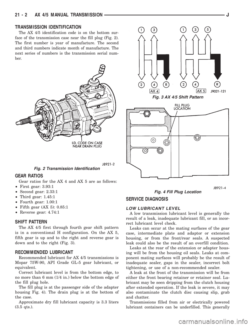
The AX 4/5 identification code is on the bottom sur-
face of the transmission case near the fill plug (Fig. 2).
The first number is year of manufacture. The second
and third numbers indicate month of manufacture. The
next series of numbers is the transmission serial num-
ber.
GEAR RATIOS
Gear ratios for the AX 4 and AX 5 are as follows:
²First gear: 3.93:1
²Second gear: 2.33:1
²Third gear: 1.45:1
²Fourth gear: 1.00:1
²Fifth gear (AX 5): 0.85:1
²Reverse gear: 4.74:1
SHIFT PATTERN
The AX 4/5 first through fourth gear shift pattern
is in a conventional H configuration. On the AX 5,
fifth gear is up and to the right and reverse gear is
down and to the right (Fig. 3).
RECOMMENDED LUBRICANT
Recommended lubricant for AX 4/5 transmissions is
Mopar 75W-90, API Grade GL-5 gear lubricant, or
equivalent.
Correct lubricant level is from the bottom edge, to
no more than 6 mm (1/4 in.) below the bottom edge of
the fill plug hole.
The fill plug is at the passenger side of the adapter
housing Fig. 4). The drain plug is at the bottom of
the case.
Approximate dry fill lubricant capacity is 3.3 liters
(3.5 qts.).
SERVICE DIAGNOSIS
LOW LUBRICANT LEVEL
A low transmission lubricant level is generally the
result of a leak, inadequate lubricant fill, or an incor-
rect lubricant level check.
Leaks can occur at the mating surfaces of the gear
case, intermediate plate and adaptor or extension
housing, or from the front/rear seals. A suspected
leak could also be the result of an overfill condition.
Leaks at the rear of the extension or adapter hous-
ing will be from the housing oil seals. Leaks at com-
ponent mating surfaces will probably be the result of
inadequate sealer, gaps in the sealer, incorrect bolt
tightening, or use of a non-recommended sealer.
A leak at the front of the transmission will be from
either the front bearing retainer or retainer seal. Lu-
bricant may be seen dripping from the clutch housing
after extended operation. If the leak is severe, it may
also contaminate the clutch disc causing slip, grab
and chatter.
Transmissions filled from air or electrically powered
lubricant containers can be underfilled. This generally
Fig. 2 Transmission Identification
Fig. 3 AX 4/5 Shift Pattern
Fig. 4 Fill Plug Location
21 - 2 AX 4/5 MANUAL TRANSMISSIONJ
Page 1565 of 2158

happens when the container delivery mechanism is im-
properly calibrated. Always check the lubricant level af-
ter filling to avoid an under fill condition.
A correct lubricant level check can only be made
when the vehicle is level; use a drive-on hoist to en-
sure this. Also allow the lubricant to settle for a
minute or so before checking. These recommenda-
tions will ensure an accurate check and avoid an un-
der-or-overfill condition.
HARD SHIFTING
Hard shifting is usually caused by a low lubricant
level, improper or contaminated lubricants, compo-
nent damage, incorrect clutch adjustment, or by a
damaged clutch pressure plate or disc.
Substantial lubricant leaks can result in gear, shift
rail, synchro and bearing damage. If a leak goes un-
detected for an extended period, the first indications
of a problem are usually hard shifting and noise.
Incorrect or contaminated lubricants can also con-
tribute to hard shifting. The consequence of using
non-recommended lubricants is noise, excessive wear,
internal bind and hard shifting.
Improper clutch release is a frequent cause of hard
shifting. Incorrect adjustment or a worn, damaged
pressure plate or disc can cause incorrect release. If
the clutch problem is advanced, gear clash during
shifts can result.
Worn or damaged synchro rings can cause gear clash
when shifting into any forward gear. In some new or re-
built transmissions, new synchro rings may tend to
stick slightly causing hard or noisy shifts. In most
cases, this condition will decline as the rings wear-in.
TRANSMISSION NOISE
Most manual transmissions make some noise dur-
ing normal operation. Rotating gears generate a mild
whine that is audible but only at extreme speeds.
Severe, highly audible transmission noise is gener-
ally the result of a lubricant problem. Insufficient,
improper, or contaminated lubricant will promote
rapid wear of gears, synchros, shift rails, forks and
bearings. The overheating caused by a lubricant
problem, can also lead to gear breakage.
TRANSMISSION REMOVAL
(1) Shift transmission into first or third gear. Then
raise vehicle on hoist.
(2) Support engine with adjustable jack stand. Po-
sition wood block between jack and oil pan to avoid
damaging pan.
(3) Disconnect necessary exhaust system components.
(4) Remove skid plate.
(5) Disconnect rear cushion and bracket from
transmission (Fig. 5).
(6) Remove rear crossmember.
Fig. 5 Rear Mount Components (YJ Shown)
JAX 4/5 MANUAL TRANSMISSION 21 - 3
Page 1575 of 2158
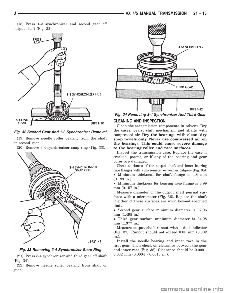
(18) Press 1-2 synchronizer and second gear off
output shaft (Fig. 32).
(19) Remove needle roller bearing from the shaft
or second gear.
(20) Remove 3-4 synchronizer snap ring (Fig. 33).
(21) Press 3-4 synchronizer and third gear off shaft
(Fig. 34).
(22) Remove needle roller bearing from shaft or
gear.
CLEANING AND INSPECTION
Clean the transmission components in solvent. Dry
the cases, gears, shift mechanism and shafts with
compressed air.Dry the bearings with clean, dry
shop towels only. Never use compressed air on
the bearings. This could cause severe damage
to the bearing roller and race surfaces.
Inspect the transmission case. Replace the case if
cracked, porous, or if any of the bearing and gear
bores are damaged.
Check thickness of the output shaft and inner bearing
race flanges with a micrometer or vernier calipers (Fig. 35).
²Minimum thickness for shaft flange is 4.8 mm
(0.189 in.)
²Minimum thickness for bearing race flange is 3.99
mm (0.157 in.)
Measure diameter of the output shaft journal sur-
faces with a micrometer (Fig. 36). Replace the shaft
if either of these surfaces are worn beyond specified
limits.
²Second gear surface minimum diameter is 37.96
mm (1.495 in.)
²Third gear surface minimum diameter is 34.98
mm (1.377 in.)
Measure output shaft runout with a dial indicator
(Fig. 37). Runout should not exceed 0.05 mm (0.002
in.).
Install the needle bearing and inner race in the
first gear. Then check oil clearance between the gear
and inner race (Fig. 38). Clearance should be 0.009 -
0.032 mm (0.0004 - 0.0013 in.).
Fig. 32 Second Gear And 1-2 Synchronizer Removal
Fig. 33 Removing 3-4 Synchronizer Snap Ring
Fig. 34 Removing 3-4 Synchronizer And Third Gear
JAX 4/5 MANUAL TRANSMISSION 21 - 13