1995 JEEP XJ rear suspension and axles
[x] Cancel search: rear suspension and axlesPage 3 of 2158
GROUP TAB LOCATOR
Introduction
0Lubrication and Maintenance
2Front Suspension and Axle
3Rear Suspension and Axles
5Brakes
6Clutch
7Cooling System
8Electrical
9Engines
11Exhaust System and Intake Manifold
13Frame and Bumpers
14Fuel System
16Propeller Shafts
19Steering
21Transmission and Transfer Cases
22Wheels and Tires
23Body Components
24Heating and Air Conditioning
25Emission Control Systems
Index
Service Manual Comment Forms (Rear of Manual)
Page 91 of 2158
(5) Lubricate all differential components with hy-
poid gear lubricant.
PINION GEAR DEPTH INFORMATION
Ring and pinion gears are supplied as matched sets
only. The identifying numbers for the ring and pinion
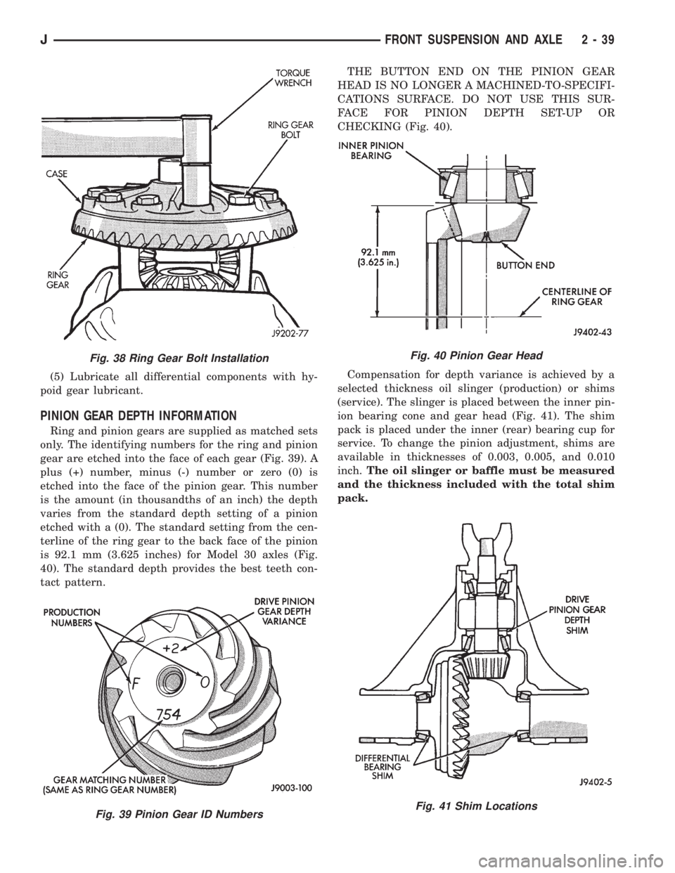
gear are etched into the face of each gear (Fig. 39). A
plus (+) number, minus (-) number or zero (0) is
etched into the face of the pinion gear. This number
is the amount (in thousandths of an inch) the depth
varies from the standard depth setting of a pinion
etched with a (0). The standard setting from the cen-
terline of the ring gear to the back face of the pinion
is 92.1 mm (3.625 inches) for Model 30 axles (Fig.
40). The standard depth provides the best teeth con-
tact pattern.THE BUTTON END ON THE PINION GEAR
HEAD IS NO LONGER A MACHINED-TO-SPECIFI-
CATIONS SURFACE. DO NOT USE THIS SUR-
FACE FOR PINION DEPTH SET-UP OR
CHECKING (Fig. 40).
Compensation for depth variance is achieved by a
selected thickness oil slinger (production) or shims
(service). The slinger is placed between the inner pin-
ion bearing cone and gear head (Fig. 41). The shim
pack is placed under the inner (rear) bearing cup for
service. To change the pinion adjustment, shims are
available in thicknesses of 0.003, 0.005, and 0.010
inch.The oil slinger or baffle must be measured
and the thickness included with the total shim
pack.
Fig. 38 Ring Gear Bolt Installation
Fig. 39 Pinion Gear ID Numbers
Fig. 40 Pinion Gear Head
Fig. 41 Shim Locations
JFRONT SUSPENSION AND AXLE 2 - 39
Page 102 of 2158
REAR SUSPENSION AND AXLES
CONTENTS
page page
8 1/4 AXLE............................ 30
AXLE NOISE/VIBRATION DIAGNOSIS......... 9
AXLE SPECIFICATIONS................... 51
GENERAL INFORMATION.................. 1
MODEL 35 AXLE........................ 13TORQUE SPECIFICATIONS................ 51
TRAC-LOK DIFFERENTIAL................. 45
XJ SUSPENSION......................... 3
YJ SUSPENSION......................... 6
GENERAL INFORMATION
SUSPENSION COMPONENTS
The Jeep rear suspension is comprised of;
²Drive axle
²Leaf springs
²Dual-action shock absorbers
²Track bar (YJ vehicles)
²Stabilizer bar (XJ vehicles)
²Jounce bumpers
The rear suspension design uses semi-elliptic
multi-leaf springs and a solid drive axle. The forward
end of the springs are mounted to the frame rail
hangers through rubber bushings. The bushings iso-
late road noise as the springs move. The rearward
end of the springs are attached to the frame by the
use of shackles. Again the spring and shackles use
rubber bushings to isolate road noise. The shackles
allow the springs to change their length as the vehi-
cle moves over various road conditions. The spring
and axle travel is limited through the use of bumpers
mounted on frame.
All suspension components that use bushings
should be tightened with the vehicle at normal ride
height. If the springs are not at normal ride position,
vehicle ride comfort could be affected. Rubber bush-
ings must never be lubricated.
The springs are attached to the axle pads with U-
bolts and plates. The springs use a center bolt that
holds the spring leafs in position. The bolt is also
used to locate the spring assembly to the axle pad.
Ride control is accomplished through the use of du-
al-action shock absorbers. The shocks dampen the
jounce and rebound as the vehicle travels over vari-
ous road conditions. The top of shock absorbers are
bolted to the frame bracket. The bottom of the shocks
are bolted to the axle bracket.
The stabilizer bar on the XJ is used to minimize
vehicle rear sway during turns. The bar helps the ve-
hicle maintain a flat attitude to the road surface. The
bar extends across the underside of the chassis and
connects to the frame rails. The links are connectedto the axle brackets. All mounting points of the sta-
bilizer bar are isolated by bushings.
The track bar on the YJ is used to minimize rear
axle side-to-side movement. The track bar is attached
to the frame rail bracket and axle bracket and is iso-
lated with bushings.
The jounce bumpers are used to limit the jounce
and rebound travel of the suspension.
AXLES
The Model 35 axle is standard for XJ and YJ vehi-
cles. The 8 1/4 axle is available in XJ vehicles with-
out ABS brakes.
The Model 35 and 8 1/4 axle housings has a cast
iron center section. Two steel axle shaft tubes are
pressed into the differential housing and welded.
It is not necessary to remove the axle from the ve-
hicle for service. A removable differential cover is
provided for routine vehicle service. If the differential
housing is damaged, the complete axle assembly can
be removed.
For complete drive axle assembly removal and in-
stallation refer to Drive Axle Assembly Replacement
in this Group.
IDENTIFICATION
Model 35 axle has the assembly part number and
gear ratio listed on a tag. The tag is attached to the left
side of the housing cover (Fig. 1). Build date identifica-
tion codes on axles are stamped on the axle shaft tube
cover side. The Model 35 axle has a flat housing cover
gasket flange at the outer edge (Fig. 1).
The 8 1/4 axle has the build date code and gear ra-
tio tags attached to the housing cover (Fig. 2). The
housing cover gasket has a rolled gasket flange at
the outer edge (Fig. 2).
²The Model 35 axle has shaft tubes that are 2.625
inch (66.67 mm) in diameter.
²The 8 1/4 axle has axle shaft tubes that are 3.0-
inch (76.2 mm) in diameter.
JREAR SUSPENSION AND AXLES 3 - 1
Page 103 of 2158
STANDARD DIFFERENTIAL OPERATION
The differential gear system divides the torque be-
tween the axle shafts. It allows the axle shafts to ro-
tate at different speeds when turning corners.
Each differential side gear is splined to an axle
shaft. The pinion gears are mounted on a pinion
mate shaft and are free to rotate on the shaft. The
pinion gear is fitted in a bore in the differential case
and is positioned at a right angle to the axle shafts.
In operation, power flow occurs as follows:
²The pinion gear rotates the ring gear²The ring gear (bolted to the differential case) ro-
tates the case
²The differential pinion gears (mounted on the pin-
ion mate shaft in the case) rotate the side gears
²The side gears (splined to the axle shafts) rotate
the shafts
During straight-ahead driving, the differential pin-
ion gears do not rotate on the pinion mate shaft. This
occurs because input torque applied to the gears is
divided and distributed equally between the two side
gears. As a result, the pinion gears revolve with the
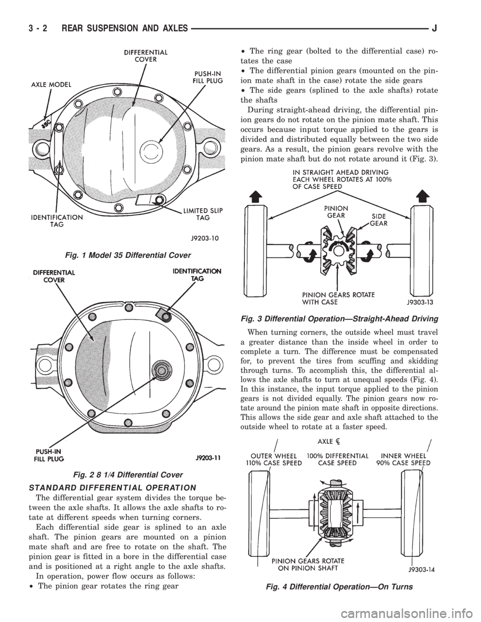
pinion mate shaft but do not rotate around it (Fig. 3).
When turning corners, the outside wheel must travel
a greater distance than the inside wheel in order to
complete a turn. The difference must be compensated
for, to prevent the tires from scuffing and skidding
through turns. To accomplish this, the differential al-
lows the axle shafts to turn at unequal speeds (Fig. 4).
In this instance, the input torque applied to the pinion
gears is not divided equally. The pinion gears now ro-
tate around the pinion mate shaft in opposite directions.
This allows the side gear and axle shaft attached to the
outside wheel to rotate at a faster speed.
Fig. 4 Differential OperationÐOn Turns
Fig. 1 Model 35 Differential Cover
Fig. 2 8 1/4 Differential Cover
Fig. 3 Differential OperationÐStraight-Ahead Driving
3 - 2 REAR SUSPENSION AND AXLESJ
Page 104 of 2158
XJ SUSPENSION
INDEX
page page
Leaf Spring............................... 4
Leaf Spring Eye Bushing Replacement.......... 5
Shock Absorber........................... 4Spring and Shock Diagnosis.................. 3
Stabilizer Bar............................. 5
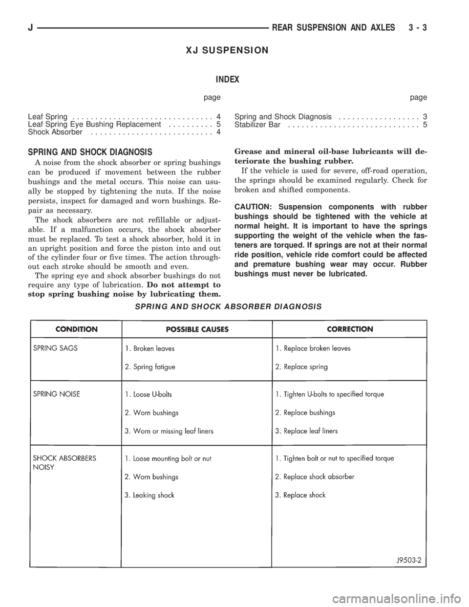
SPRING AND SHOCK DIAGNOSIS
A noise from the shock absorber or spring bushings
can be produced if movement between the rubber
bushings and the metal occurs. This noise can usu-
ally be stopped by tightening the nuts. If the noise
persists, inspect for damaged and worn bushings. Re-
pair as necessary.
The shock absorbers are not refillable or adjust-
able. If a malfunction occurs, the shock absorber
must be replaced. To test a shock absorber, hold it in
an upright position and force the piston into and out
of the cylinder four or five times. The action through-
out each stroke should be smooth and even.
The spring eye and shock absorber bushings do not
require any type of lubrication.Do not attempt to
stop spring bushing noise by lubricating them.Grease and mineral oil-base lubricants will de-
teriorate the bushing rubber.
If the vehicle is used for severe, off-road operation,
the springs should be examined regularly. Check for
broken and shifted components.
CAUTION: Suspension components with rubber
bushings should be tightened with the vehicle at
normal height. It is important to have the springs
supporting the weight of the vehicle when the fas-
teners are torqued. If springs are not at their normal
ride position, vehicle ride comfort could be affected
and premature bushing wear may occur. Rubber
bushings must never be lubricated.
SPRING AND SHOCK ABSORBER DIAGNOSIS
JREAR SUSPENSION AND AXLES 3 - 3
Page 105 of 2158
SHOCK ABSORBER
REMOVAL
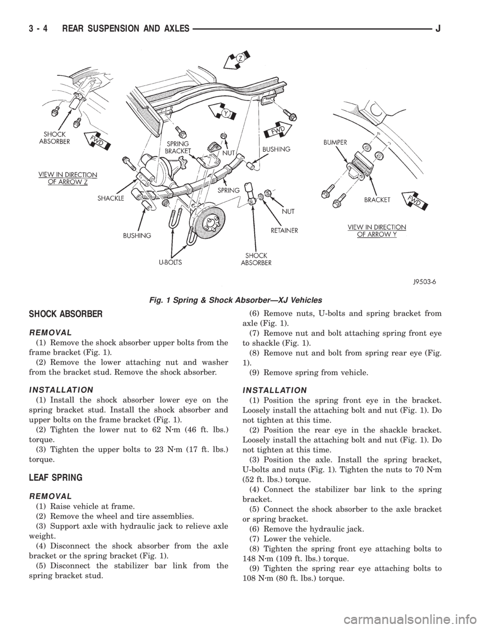
(1) Remove the shock absorber upper bolts from the
frame bracket (Fig. 1).
(2) Remove the lower attaching nut and washer
from the bracket stud. Remove the shock absorber.
INSTALLATION
(1) Install the shock absorber lower eye on the
spring bracket stud. Install the shock absorber and
upper bolts on the frame bracket (Fig. 1).
(2) Tighten the lower nut to 62 Nzm (46 ft. lbs.)
torque.
(3) Tighten the upper bolts to 23 Nzm (17 ft. lbs.)
torque.
LEAF SPRING
REMOVAL
(1) Raise vehicle at frame.
(2) Remove the wheel and tire assemblies.
(3) Support axle with hydraulic jack to relieve axle
weight.
(4) Disconnect the shock absorber from the axle
bracket or the spring bracket (Fig. 1).
(5) Disconnect the stabilizer bar link from the
spring bracket stud.(6) Remove nuts, U-bolts and spring bracket from
axle (Fig. 1).
(7) Remove nut and bolt attaching spring front eye
to shackle (Fig. 1).
(8) Remove nut and bolt from spring rear eye (Fig.
1).
(9) Remove spring from vehicle.
INSTALLATION
(1) Position the spring front eye in the bracket.
Loosely install the attaching bolt and nut (Fig. 1). Do
not tighten at this time.
(2) Position the rear eye in the shackle bracket.
Loosely install the attaching bolt and nut (Fig. 1). Do
not tighten at this time.
(3) Position the axle. Install the spring bracket,
U-bolts and nuts (Fig. 1). Tighten the nuts to 70 Nzm
(52 ft. lbs.) torque.
(4) Connect the stabilizer bar link to the spring
bracket.
(5) Connect the shock absorber to the axle bracket
or spring bracket.
(6) Remove the hydraulic jack.
(7) Lower the vehicle.
(8) Tighten the spring front eye attaching bolts to
148 Nzm (109 ft. lbs.) torque.
(9) Tighten the spring rear eye attaching bolts to
108 Nzm (80 ft. lbs.) torque.
Fig. 1 Spring & Shock AbsorberÐXJ Vehicles
3 - 4 REAR SUSPENSION AND AXLESJ
Page 106 of 2158
LEAF SPRING EYE BUSHING REPLACEMENT
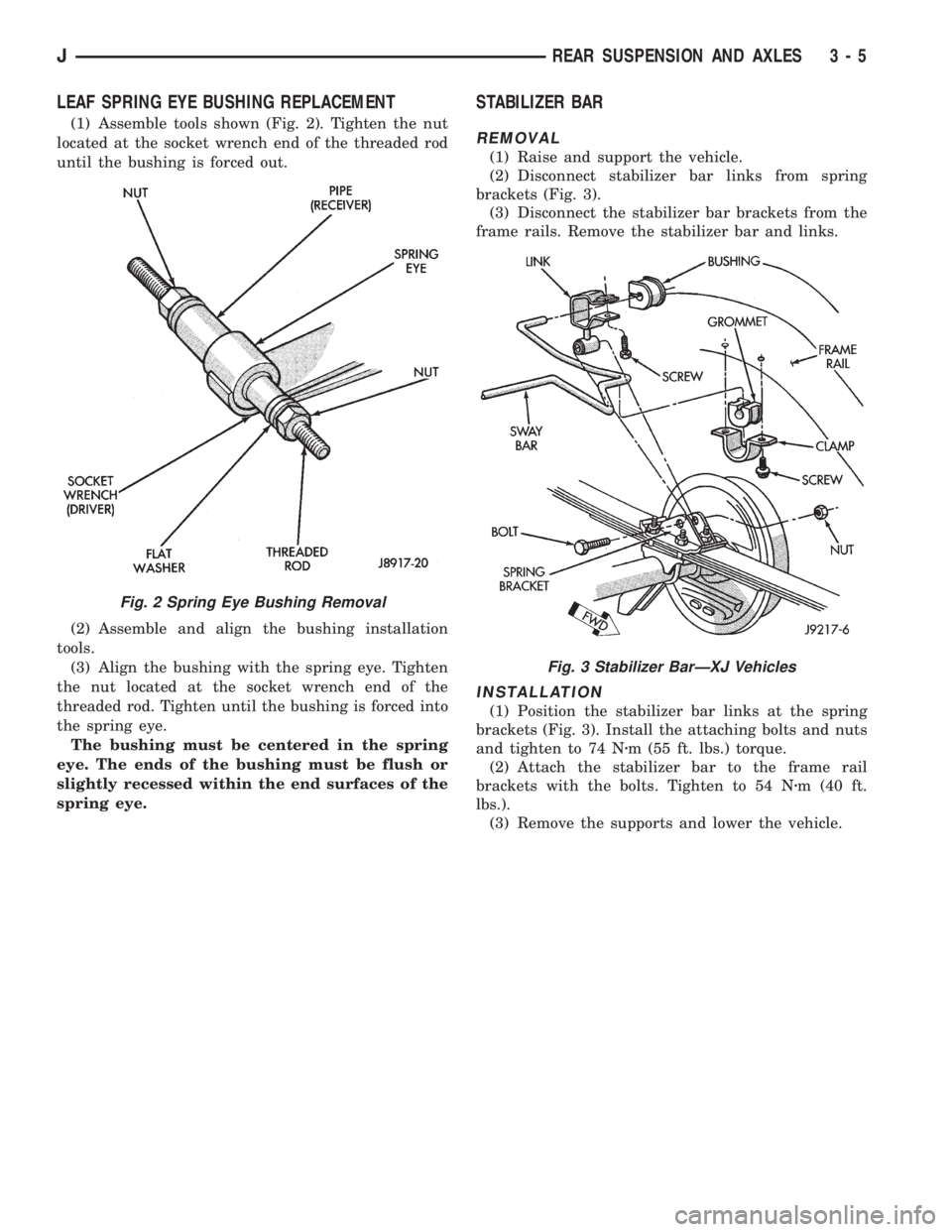
(1) Assemble tools shown (Fig. 2). Tighten the nut
located at the socket wrench end of the threaded rod
until the bushing is forced out.
(2) Assemble and align the bushing installation
tools.
(3) Align the bushing with the spring eye. Tighten
the nut located at the socket wrench end of the
threaded rod. Tighten until the bushing is forced into
the spring eye.
The bushing must be centered in the spring
eye. The ends of the bushing must be flush or
slightly recessed within the end surfaces of the
spring eye.
STABILIZER BAR
REMOVAL
(1) Raise and support the vehicle.
(2) Disconnect stabilizer bar links from spring
brackets (Fig. 3).
(3) Disconnect the stabilizer bar brackets from the
frame rails. Remove the stabilizer bar and links.
INSTALLATION
(1) Position the stabilizer bar links at the spring
brackets (Fig. 3). Install the attaching bolts and nuts
and tighten to 74 Nzm (55 ft. lbs.) torque.
(2) Attach the stabilizer bar to the frame rail
brackets with the bolts. Tighten to 54 Nzm (40 ft.
lbs.).
(3) Remove the supports and lower the vehicle.
Fig. 2 Spring Eye Bushing Removal
Fig. 3 Stabilizer BarÐXJ Vehicles
JREAR SUSPENSION AND AXLES 3 - 5
Page 107 of 2158
YJ SUSPENSION
INDEX
page page
Leaf Spring............................... 7
Leaf Spring Eye Bushing Replacement.......... 7
Shock Absorber........................... 7Spring and Shock Diagnosis.................. 6
Track Bar................................ 8
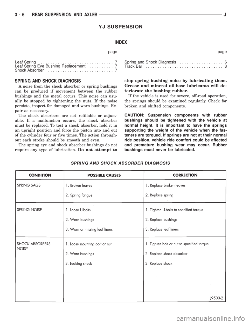
SPRING AND SHOCK DIAGNOSIS
A noise from the shock absorber or spring bushings
can be produced if movement between the rubber
bushings and the metal occurs. This noise can usu-
ally be stopped by tightening the nuts. If the noise
persists, inspect for damaged and worn bushings. Re-
pair as necessary.
The shock absorbers are not refillable or adjust-
able. If a malfunction occurs, the shock absorber
must be replaced. To test a shock absorber, hold it in
an upright position and force the piston into and out
of the cylinder four or five times. The action through-
out each stroke should be smooth and even.
The spring eye and shock absorber bushings do not
require any type of lubrication.Do not attempt tostop spring bushing noise by lubricating them.
Grease and mineral oil-base lubricants will de-
teriorate the bushing rubber.
If the vehicle is used for severe, off-road operation,
the springs should be examined regularly. Check for
broken and shifted components.
CAUTION: Suspension components with rubber
bushings should be tightened with the vehicle at
normal height. It is important to have the springs
supporting the weight of the vehicle when the fas-
teners are torqued. If springs are not at their normal
ride position, vehicle ride comfort could be affected
and premature bushing wear may occur. Rubber
bushings must never be lubricated.
SPRING AND SHOCK ABSORBER DIAGNOSIS
3 - 6 REAR SUSPENSION AND AXLESJ