1995 JEEP XJ fuse diagram
[x] Cancel search: fuse diagramPage 865 of 2158

HELPFUL INFORMATION
²If the system loses ground for the Z11 circuits at
the right rear of the engine, the vehicle will not op-
erate. Check the connection at the ganged-ground cir-
cuit eyelet.
²Circuit F12 splices to supply battery voltage to the
vehicle speed control switch, back-up lamp switch,
A/C compressor clutch relay, windshield washer fluid
level sensor and radiator fan relay.
BRAKE SWITCH INPUT
Circuit K29 provides the brake switch input to the
PCM. Circuit K29 connects to cavity 29 of the PCM.
POWER (DEVICE) GROUND
Circuit Z12 connects to cavities 11 and 12 of the
PCM. The Z12 circuit provides ground for PCM inter-
nal drivers that operate high current devices like the
injectors and ignition coil.
Internal to the PCM, the power (device) ground cir-
cuit connects to the PCM sensor return circuit (from
circuit K4).
HELPFUL INFORMATION
²The grounding point for circuit Z12 is the right
rear of the engine.
²If the system loses ground for the Z12 circuits at
the rear of the engine, the vehicle will not operate.
Check the connection at the ganged-ground circuit
eyelet.
DIAGRAM INDEX
Component Page
Automatic Shut Down Relay.................8W-30-6
Camshaft Position Sensor...................8W-30-8
Crankshaft Position Sensor..................8W-30-9
Data Link Connector......................8W-30-11
Distributor Ignition Coil....................8W-30-11
Engine Coolant Temperature Sensor.............8W-30-9
Fuel Injector #1.........................8W-30-7
Fuel Injector #2.........................8W-30-7
Fuel Injector #3.........................8W-30-7
Fuel Injector #4.........................8W-30-7
Fuel Injector #5.........................8W-30-7
Fuel Injector #6.........................8W-30-7
Fuel Pump Relay........................8W-30-12
Fuel Tank Gauge Level Sending Unit...........8W-30-12
Fuse 2 (PDC)...........................8W-30-6
Fuse 6 (PDC)...........................8W-30-6
Fuse 11 (PDC).......................8W-30-6, 11
Fuse 14 (PDC)..........................8W-30-6
Heated Oxygen Sensor....................8W-30-10
Idle Air Control Motor.....................8W-30-10
Ignition Switch.......................8W-30-6, 12
Instrument Cluster....................8W-30-11, 12
Intake Air Temperature Sensor................8W-30-9
MAP Sensor............................8W-30-8
Powertrain Control Module.............8W-30-6 thru 12
Throttle Position Sensor....................8W-30-8
Vehicle Speed Sensor.....................8W-30-11
J8W-30 FUEL/IGNITIONÐXJ-RHD 8W - 30 - 5
Page 873 of 2158

TRANSMISSION CONTROLS
FOUR-WHEEL DRIVE (4WD) SWITCH
When the 4WD switch closes, circuit Z1 provides
ground for the 4WD indicator lamp in the instrument
cluster. Circuit F87 connects to the instrument clus-
ter and supplies battery voltage to the 4WD indicator
lamp. Circuit 107 connects the indicator lamp to the
4WD switch. Circuit 106 connects the lamp to the in-
strument cluster and circuit F87.
TRANSMISSION COMFORT SWITCH
Circuit T17 from fuse 12 in the Power Distribution
Center (PDC) supplies battery voltage to the trans-
mission comfort switch. Circuit Z1 provides ground
for the switch. Circuit T177 Connects the switch to
the Transmission Control Module (TCM).
TRANSMISSION CONTROL MODULE
Vehicles equipped with the 4.0L engine have elec-
tronically controlled solenoids in the automatic trans-
mission valve body.
The transmission control module (TCM) receives
inputs from the throttle position sensor (TPS) on cir-
cuit K22 and the stop lamp switch on circuit K29.
Circuit K4 connects to the TCM to provide ground for
the TPS signal.
The TCM receives the transmission output speed
sensor signal on circuit 505. Circuit A14 from fuse 2
in the Power Distribution Center (PDC) supplies bat-
tery voltage to the TCM. Circuit T17 from fuse 12 in
the PDC also connects to the TCM. Circuit Z12 pro-
vides ground for the TCM.The TCM powers the S1 solenoid on circuit 510,
the S2 solenoid on circuit 509, and the S3 solenoid on
circuit 508. Circuit Z12 provides ground for the S1,
S2, and S3 solenoids.
Circuits 506 and 507 from the Park/Neutral posi-
tion switch connect to the TCM. Circuits 506 and 507
tell the TCM what drive range the transmission is in.
DATA LINK CONNECTOR
Circuit 137 from the TCM connects to the data link
connector. Circuit F39 from fuse 5 in the PDC sup-
plies power to the data link connector. Circuit Z12
provides ground for the data link connector.
DIAGRAM INDEX
Component Page
ABS Data Link Connector...................8W-31-3
4-WD Indicator Lamp......................8W-31-4
4-WD Indicator Switch.....................8W-31-4
Fuse 2 (PDC)...........................8W-31-4
Fuse 6 (PDC).........................8W-31-2, 3
Fuse 11 (PDC)..........................8W-31-3
Fuse 12 (PDC)..........................8W-31-2
Ignition Switch........................8W-31-2, 3
Park/Neutral Position Switch.................8W-31-3
Telltale Connector (Instrument Cluster)...........8W-31-4
Transmission Comfort Switch.................8W-31-2
Transmission Control Module.............8W-31-2, 3, 4
Transmission Valve Body Solenoids.............8W-31-4
J8W-31 TRANSMISSION CONTROLSÐXJ-RHD 8W - 31 - 1
Page 877 of 2158

ANTI-LOCK BRAKES
INDEX
page page
ABS Power Relay.......................... 1
ABS Pump Motor Relay..................... 1
ABS Warning Lamp........................ 2
Acceleration Switch......................... 1
Brake Pedal Travel Sensor................... 2
Brake Switch Input......................... 2Data Link Connector........................ 2
Diagram Index............................ 3
General Information........................ 1
Hydraulic Control Unit....................... 2
Pump Motor Speed Sensor................... 2
Wheel Speed Sensors...................... 1
GENERAL INFORMATION
Three fuses supply power for the Anti-Lock Brake
System (ABS); fuses 6 and 10 in the Power Distribu-
tion Center (PDC) and fuse 2 in the fuse block. Fuses
6 and 10 in the PDC are connected directly to battery
voltage and are HOT all times. Fuse 2 in the fuse
block is HOT when the ignition switch is the RUN
Position.
In the RUN position, the ignition switch connects
circuit A1 from fuse 6 in the PDC with circuit A38.
Circuit A38 connects to a bus bar in the fuse block.
The bus bar feeds circuit B236 through fuse 2. Fuse
2 is a 2 amp fuse.
Circuit B236 connects to the coil side of the ABS
power relay and cavity 53 of the ABS control module.
Circuit Z1 provides ground for the ABS control
module. Circuit Z1 connects to cavities 1 and 19 of
the ABS control module.
Refer to group 5, Brakes for operational descrip-
tions of ABS system components.
WHEEL SPEED SENSORS
The all wheel anti-lock system uses four wheel
speed sensors; one for each wheel. Each sensor con-
verts wheel speed into an electrical signal that it
transmits to the ABS control module. A pair of
twisted wires connect to each sensor to provide sig-
nals to the ABS control module.
Circuits B6 and B7 provide signals to ABS control
module from the right front wheel speed sensor. Cir-
cuit B6 which provides the LOW signal connects to
cavity 29 of the ABS control module. Circuit B7 con-
nects to cavity 47 of the module and provides the
HIGH signal.
Circuits B8 and B9 provide signals to ABS control
module from the left front wheel speed sensor. Cir-
cuit B8, which provides the LOW signal, connects to
cavity 30 of the ABS control module. Circuit B9 con-
nects to cavity 48 of the module and provides the
HIGH signal.
Circuits B1 and B2 provide signals to ABS control
module from the right rear wheel speed sensor. Cir-
cuit B1 which provides the LOW signal connects tocavity 45 of the ABS control module. Circuit B2 con-
nects to cavity 27 of the module and provides the
HIGH signal.
Circuits B4 and B3 provide signals to ABS control
module from the left rear wheel speed sensor. Circuit
B3, which provides the LOW signal, connects to cav-
ity 28 of the ABS control module. Circuit B4 connects
to cavity 46 of the module and provides the HIGH
signal.
ACCELERATION SWITCH
During four-wheel drive operation, the acceleration
switch provides deceleration data to the ABS control
module. Refer to Group 5, Brakes for additional in-
formation.
Circuits B515, B516, and B517 connect the acceler-
ation sensor to the ABS control module. Circuits
B515 and B516 provide switch states while circuit
B517 provides ground. At the ABS control module cir-
cuit B515 connects to cavity 25, circuit B516 connects
to cavity 43 and circuit B517 connects to cavity 26.
ABS POWER RELAY
The ABS power relay is located in the power distri-
bution center (PDC). When the ABS module grounds
the ABS power relay on circuit B207, the relay
switches to connect circuit A20 from PDC fuse 10 to
circuit B235. Circuit B236 from fuse 7 in the fuse
block splices to feed the coil side of the ABS power
relay. Circuit B207 connects to cavity 34 of the ABS
control module.
Circuit B235 is double crimped at the ABS power
relay. One branch of circuit B235 supplies power to
the coil side of the ABS pump motor relay. The other
branch of circuit B235 splices to cavities 3 and 33 of
the ABS control module and to the hydraulic control
unit.
ABS PUMP MOTOR RELAY
The ABS pump motor relay in the power distribu-
tion center (PDC) supplies voltage to the ABS pump
motor. When the ABS power relay energizes, circuit
B235 supplies battery voltage to the coil side of the
J8W-32 ANTI-LOCK BRAKESÐXJ-RHD 8W - 32 - 1
Page 879 of 2158

DIAGRAM INDEX
Component Page
ABS Control Module..................8W-32-4 thru 8
ABS Hydraulic Unit.......................8W-32-6
ABS Power Relay........................8W-32-4
ABS Pump Motor........................8W-32-4
ABS Pump Motor Relay....................8W-32-5
Data Link Connector......................8W-32-8
Diode................................8W-32-6
Fuse 6 (PDC)...........................8W-32-5
Fuse 7 (PDC)...........................8W-32-8
Fuse 8 (PDC)...........................8W-32-5
Fuse 10 (PDC)..........................8W-32-4
Fuse 13 (PDC)..........................8W-32-8
Fuse 18 (Fuse Block)......................8W-32-5
G-Sensor..............................8W-32-8
Ignition Switch..........................8W-32-5
Powertrain Control Module..................8W-32-8
Telltale Connector (Instrument Cluster)...........8W-32-6
Wheel Speed Sensors......................8W-32-7
J8W-32 ANTI-LOCK BRAKESÐXJ-RHD 8W - 32 - 3
Page 885 of 2158

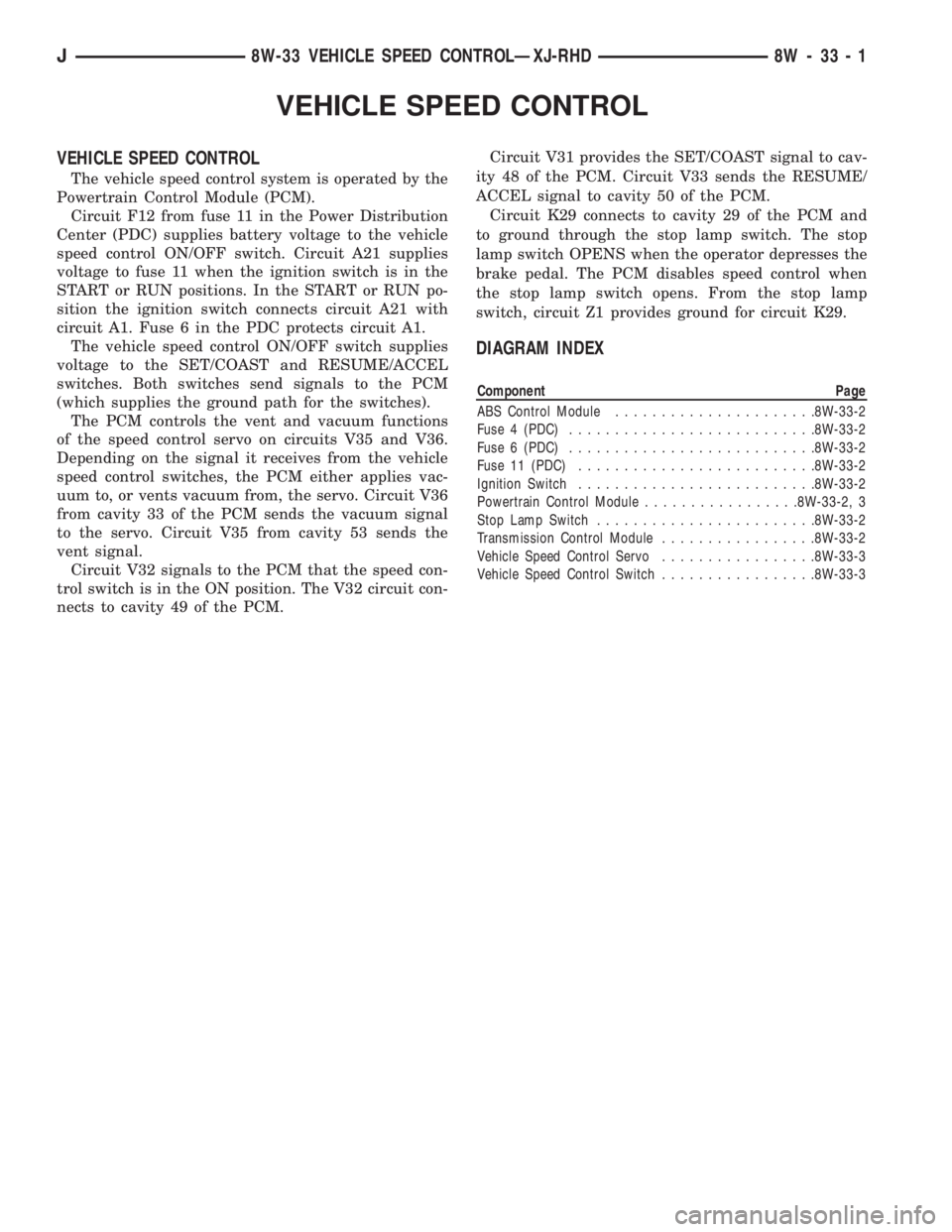
VEHICLE SPEED CONTROL
VEHICLE SPEED CONTROL
The vehicle speed control system is operated by the
Powertrain Control Module (PCM).
Circuit F12 from fuse 11 in the Power Distribution
Center (PDC) supplies battery voltage to the vehicle
speed control ON/OFF switch. Circuit A21 supplies
voltage to fuse 11 when the ignition switch is in the
START or RUN positions. In the START or RUN po-
sition the ignition switch connects circuit A21 with
circuit A1. Fuse 6 in the PDC protects circuit A1.
The vehicle speed control ON/OFF switch supplies
voltage to the SET/COAST and RESUME/ACCEL
switches. Both switches send signals to the PCM
(which supplies the ground path for the switches).
The PCM controls the vent and vacuum functions
of the speed control servo on circuits V35 and V36.
Depending on the signal it receives from the vehicle
speed control switches, the PCM either applies vac-
uum to, or vents vacuum from, the servo. Circuit V36
from cavity 33 of the PCM sends the vacuum signal
to the servo. Circuit V35 from cavity 53 sends the
vent signal.
Circuit V32 signals to the PCM that the speed con-
trol switch is in the ON position. The V32 circuit con-
nects to cavity 49 of the PCM.Circuit V31 provides the SET/COAST signal to cav-
ity 48 of the PCM. Circuit V33 sends the RESUME/
ACCEL signal to cavity 50 of the PCM.
Circuit K29 connects to cavity 29 of the PCM and
to ground through the stop lamp switch. The stop
lamp switch OPENS when the operator depresses the
brake pedal. The PCM disables speed control when
the stop lamp switch opens. From the stop lamp
switch, circuit Z1 provides ground for circuit K29.
DIAGRAM INDEX
Component Page
ABS Control Module......................8W-33-2
Fuse 4 (PDC)...........................8W-33-2
Fuse 6 (PDC)...........................8W-33-2
Fuse 11 (PDC)..........................8W-33-2
Ignition Switch..........................8W-33-2
Powertrain Control Module.................8W-33-2, 3
Stop Lamp Switch........................8W-33-2
Transmission Control Module.................8W-33-2
Vehicle Speed Control Servo.................8W-33-3
Vehicle Speed Control Switch.................8W-33-3
J8W-33 VEHICLE SPEED CONTROLÐXJ-RHD 8W - 33 - 1
Page 891 of 2158

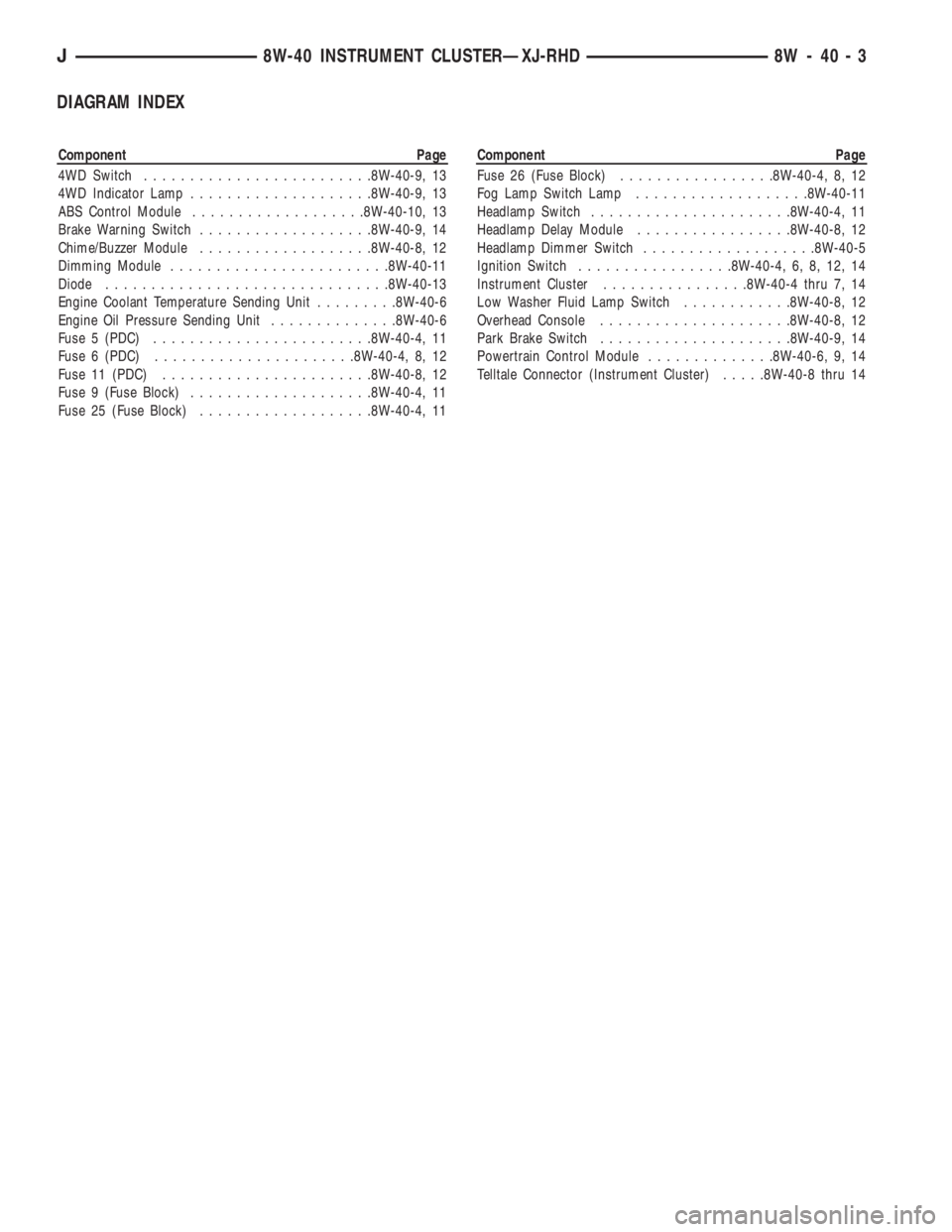
DIAGRAM INDEX
Component Page
4WD Switch.........................8W-40-9, 13
4WD Indicator Lamp....................8W-40-9, 13
ABS Control Module...................8W-40-10, 13
Brake Warning Switch...................8W-40-9, 14
Chime/Buzzer Module...................8W-40-8, 12
Dimming Module........................8W-40-11
Diode...............................8W-40-13
Engine Coolant Temperature Sending Unit.........8W-40-6
Engine Oil Pressure Sending Unit..............8W-40-6
Fuse 5 (PDC)........................8W-40-4, 11
Fuse 6 (PDC)......................8W-40-4, 8, 12
Fuse 11 (PDC).......................8W-40-8, 12
Fuse 9 (Fuse Block)....................8W-40-4, 11
Fuse 25 (Fuse Block)...................8W-40-4, 11Component Page
Fuse 26 (Fuse Block).................8W-40-4, 8, 12
Fog Lamp Switch Lamp...................8W-40-11
Headlamp Switch......................8W-40-4, 11
Headlamp Delay Module.................8W-40-8, 12
Headlamp Dimmer Switch...................8W-40-5
Ignition Switch.................8W-40-4, 6, 8, 12, 14
Instrument Cluster................8W-40-4 thru 7, 14
Low Washer Fluid Lamp Switch............8W-40-8, 12
Overhead Console.....................8W-40-8, 12
Park Brake Switch.....................8W-40-9, 14
Powertrain Control Module..............8W-40-6, 9, 14
Telltale Connector (Instrument Cluster).....8W-40-8 thru 14
J8W-40 INSTRUMENT CLUSTERÐXJ-RHD 8W - 40 - 3
Page 903 of 2158

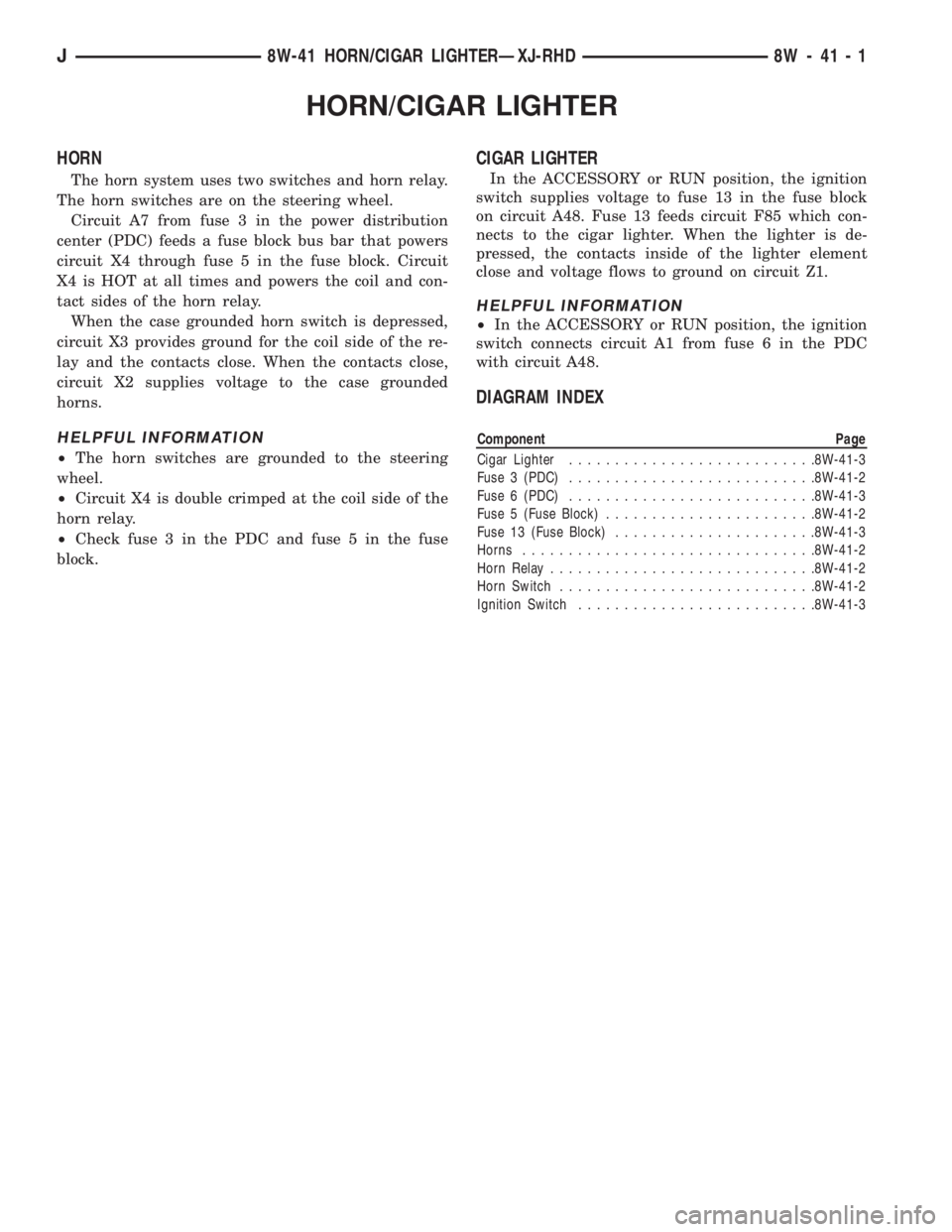
HORN/CIGAR LIGHTER
HORN
The horn system uses two switches and horn relay.
The horn switches are on the steering wheel.
Circuit A7 from fuse 3 in the power distribution
center (PDC) feeds a fuse block bus bar that powers
circuit X4 through fuse 5 in the fuse block. Circuit
X4 is HOT at all times and powers the coil and con-
tact sides of the horn relay.
When the case grounded horn switch is depressed,
circuit X3 provides ground for the coil side of the re-
lay and the contacts close. When the contacts close,
circuit X2 supplies voltage to the case grounded
horns.
HELPFUL INFORMATION
²The horn switches are grounded to the steering
wheel.
²Circuit X4 is double crimped at the coil side of the
horn relay.
²Check fuse 3 in the PDC and fuse 5 in the fuse
block.
CIGAR LIGHTER
In the ACCESSORY or RUN position, the ignition
switch supplies voltage to fuse 13 in the fuse block
on circuit A48. Fuse 13 feeds circuit F85 which con-
nects to the cigar lighter. When the lighter is de-
pressed, the contacts inside of the lighter element
close and voltage flows to ground on circuit Z1.
HELPFUL INFORMATION
²In the ACCESSORY or RUN position, the ignition
switch connects circuit A1 from fuse 6 in the PDC
with circuit A48.
DIAGRAM INDEX
Component Page
Cigar Lighter...........................8W-41-3
Fuse 3 (PDC)...........................8W-41-2
Fuse 6 (PDC)...........................8W-41-3
Fuse 5 (Fuse Block).......................8W-41-2
Fuse 13 (Fuse Block)......................8W-41-3
Horns................................8W-41-2
Horn Relay.............................8W-41-2
Horn Switch............................8W-41-2
Ignition Switch..........................8W-41-3
J8W-41 HORN/CIGAR LIGHTERÐXJ-RHD 8W - 41 - 1
Page 907 of 2158

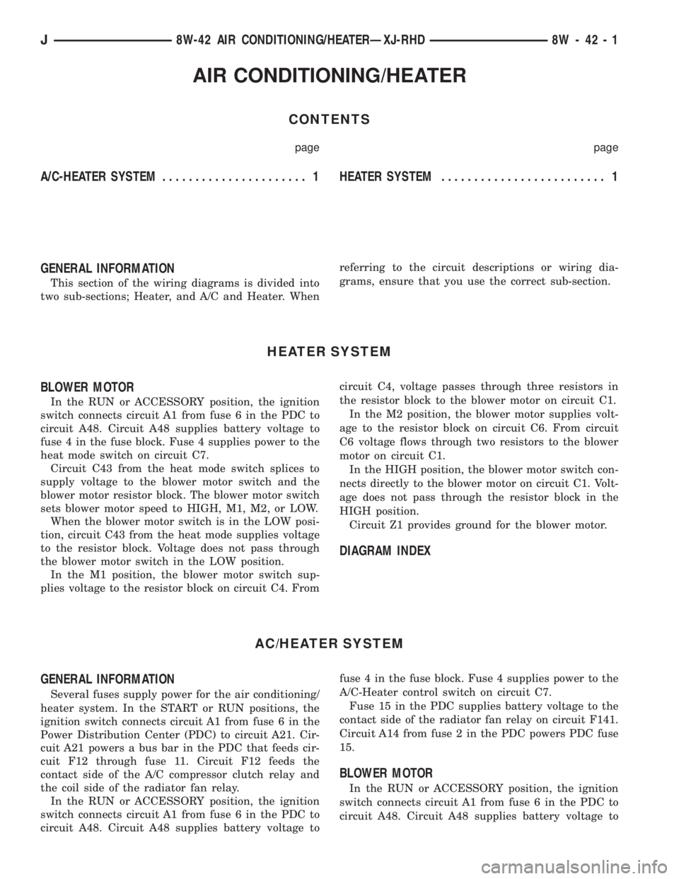
AIR CONDITIONING/HEATER
CONTENTS
page page
A/C-HEATER SYSTEM...................... 1 HEATERSYSTEM......................... 1
GENERAL INFORMATION
This section of the wiring diagrams is divided into
two sub-sections; Heater, and A/C and Heater. Whenreferring to the circuit descriptions or wiring dia-
grams, ensure that you use the correct sub-section.
HEATER SYSTEM
BLOWER MOTOR
In the RUN or ACCESSORY position, the ignition
switch connects circuit A1 from fuse 6 in the PDC to
circuit A48. Circuit A48 supplies battery voltage to
fuse 4 in the fuse block. Fuse 4 supplies power to the
heat mode switch on circuit C7.
Circuit C43 from the heat mode switch splices to
supply voltage to the blower motor switch and the
blower motor resistor block. The blower motor switch
sets blower motor speed to HIGH, M1, M2, or LOW.
When the blower motor switch is in the LOW posi-
tion, circuit C43 from the heat mode supplies voltage
to the resistor block. Voltage does not pass through
the blower motor switch in the LOW position.
In the M1 position, the blower motor switch sup-
plies voltage to the resistor block on circuit C4. Fromcircuit C4, voltage passes through three resistors in
the resistor block to the blower motor on circuit C1.
In the M2 position, the blower motor supplies volt-
age to the resistor block on circuit C6. From circuit
C6 voltage flows through two resistors to the blower
motor on circuit C1.
In the HIGH position, the blower motor switch con-
nects directly to the blower motor on circuit C1. Volt-
age does not pass through the resistor block in the
HIGH position.
Circuit Z1 provides ground for the blower motor.
DIAGRAM INDEX
AC/HEATER SYSTEM
GENERAL INFORMATION
Several fuses supply power for the air conditioning/
heater system. In the START or RUN positions, the
ignition switch connects circuit A1 from fuse 6 in the
Power Distribution Center (PDC) to circuit A21. Cir-
cuit A21 powers a bus bar in the PDC that feeds cir-
cuit F12 through fuse 11. Circuit F12 feeds the
contact side of the A/C compressor clutch relay and
the coil side of the radiator fan relay.
In the RUN or ACCESSORY position, the ignition
switch connects circuit A1 from fuse 6 in the PDC to
circuit A48. Circuit A48 supplies battery voltage tofuse 4 in the fuse block. Fuse 4 supplies power to the
A/C-Heater control switch on circuit C7.
Fuse 15 in the PDC supplies battery voltage to the
contact side of the radiator fan relay on circuit F141.
Circuit A14 from fuse 2 in the PDC powers PDC fuse
15.
BLOWER MOTOR
In the RUN or ACCESSORY position, the ignition
switch connects circuit A1 from fuse 6 in the PDC to
circuit A48. Circuit A48 supplies battery voltage to
J8W-42 AIR CONDITIONING/HEATERÐXJ-RHD 8W - 42 - 1