1995 JEEP XJ bulb
[x] Cancel search: bulbPage 1983 of 2158
(7) Move downward and mate the seal with the
right-side flange.
(8) Move to the left and mate the seal with the bot-
tom-right flange.
(9) Center and butt seal the ends together at the
centerline.
(10) Seat the remaining part of the seal with a
roller. Move the roller the from top-left half of the
seal to the right-bottom end of the seal.
LIFTGATE LICENSE PLATE LAMP HOUSINGÐXJ
REMOVAL
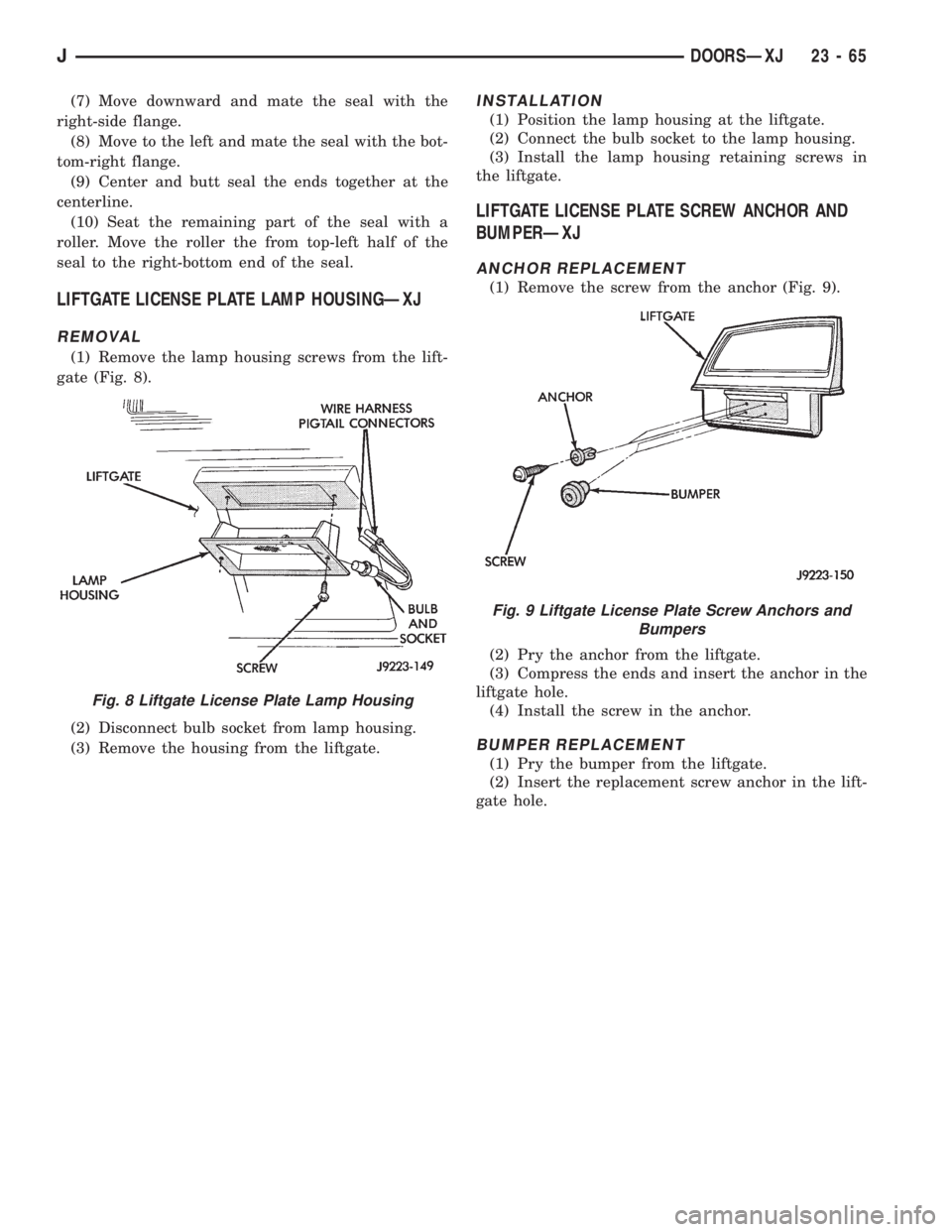
(1) Remove the lamp housing screws from the lift-
gate (Fig. 8).
(2) Disconnect bulb socket from lamp housing.
(3) Remove the housing from the liftgate.
INSTALLATION
(1) Position the lamp housing at the liftgate.
(2) Connect the bulb socket to the lamp housing.
(3) Install the lamp housing retaining screws in
the liftgate.
LIFTGATE LICENSE PLATE SCREW ANCHOR AND
BUMPERÐXJ
ANCHOR REPLACEMENT
(1) Remove the screw from the anchor (Fig. 9).
(2) Pry the anchor from the liftgate.
(3) Compress the ends and insert the anchor in the
liftgate hole.
(4) Install the screw in the anchor.
BUMPER REPLACEMENT
(1) Pry the bumper from the liftgate.
(2) Insert the replacement screw anchor in the lift-
gate hole.
Fig. 8 Liftgate License Plate Lamp Housing
Fig. 9 Liftgate License Plate Screw Anchors and
Bumpers
JDOORSÐXJ 23 - 65
Page 2022 of 2158
EXTERIOR COMPONENTS
INDEX
page page
Battery TrayÐYJ......................... 110
Body Side Step MoldingÐYJ................ 115
Body Stripes/DecalsÐYJ................... 116
Cowl Grille and ScreenÐYJ................ 109
Cowl Weatherstrip SealÐYJ................ 109
Exterior Nameplates (Adhesive-Backed)ÐYJ.... 120
External Spare/Wheel Tire CarrierÐYJ........ 133
Fender FlareÐYJ........................ 114
Fender Inner Splash ShieldsÐYJ............. 116
Fender Splash ApronsÐYJ................. 115
FendersÐYJ............................ 110
Fuel Filler Protector/NozzleÐYJ............. 121
Half Metal Door Mirror (External)ÐYJ......... 121
Hard Top Liftgate GlassÐYJ................ 124
Hard Top RepairÐYJ..................... 127
Hard Top Roof VentÐYJ................... 127
Hard TopÐYJ........................... 126Hood AlignmentÐYJ...................... 107
Hood Insulator PanelÐYJ.................. 107
Hood Safety LatchÐYJ.................... 109
HoodÐYJ.............................. 107
Liftgate Glass Weatherstrip Seal ReplacementÐYJ. 125
Radiator Grille AppliqueÐYJ................ 104
Soft Top Service InformationÐYJ............. 127
Soft Top ServiceÐYJ..................... 129
Sport BarÐYJ........................... 132
Tailgate AdjustmentÐYJ................... 121
Tailgate HingeÐYJ....................... 121
Tailgate Latch and Release HandleÐYJ........ 122
Tailgate Latch StrikerÐYJ.................. 123
Tailgate Lock CylinderÐYJ................. 122
Tailgate Weatherstrip SealÐYJ.............. 123
TailgateÐYJ............................ 121
Wheelhouse Splash LinersÐYJ.............. 115
RADIATOR GRILLE APPLIQUEÐYJ
REMOVAL
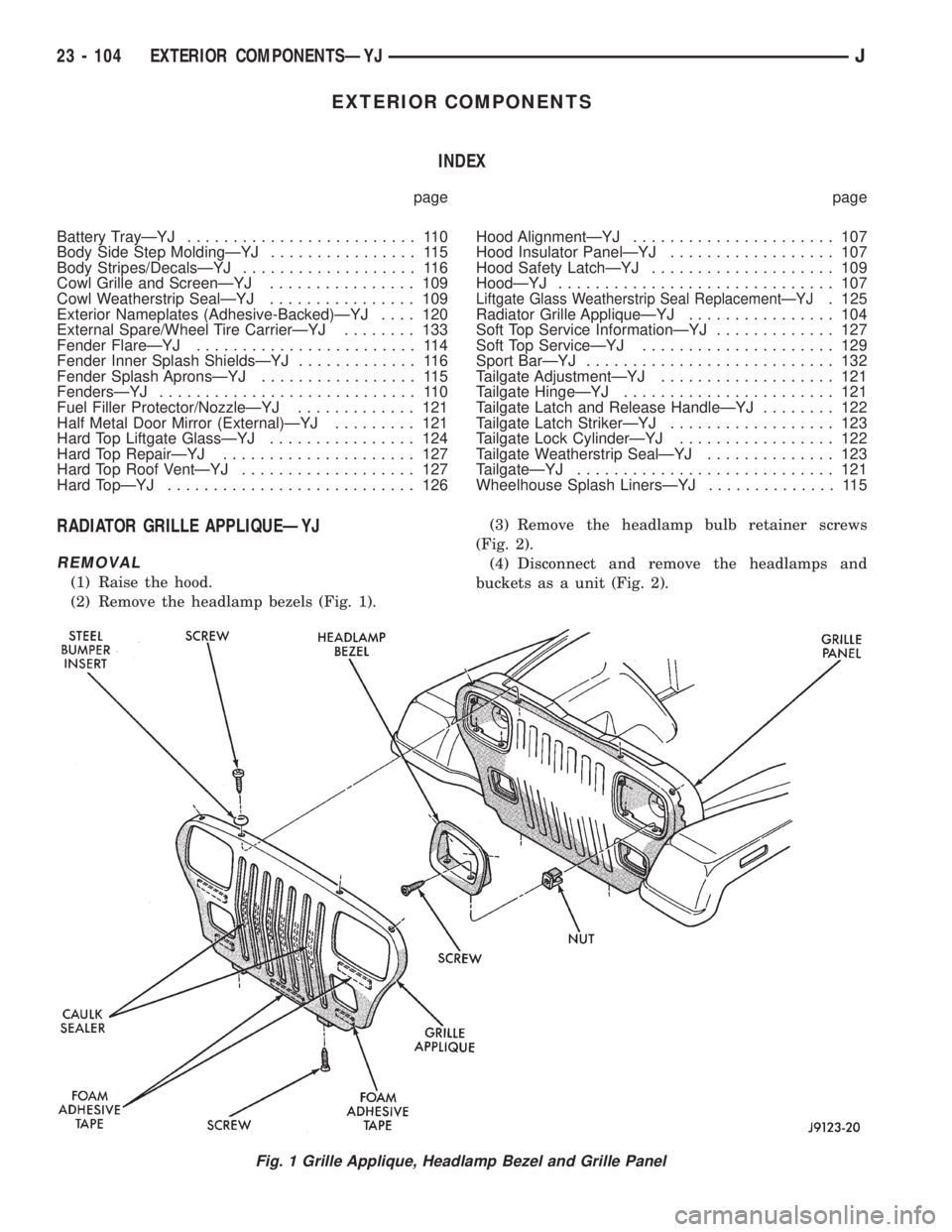
(1) Raise the hood.
(2) Remove the headlamp bezels (Fig. 1).(3) Remove the headlamp bulb retainer screws
(Fig. 2).
(4) Disconnect and remove the headlamps and
buckets as a unit (Fig. 2).
Fig. 1 Grille Applique, Headlamp Bezel and Grille Panel
23 - 104 EXTERIOR COMPONENTSÐYJJ
Page 2023 of 2158
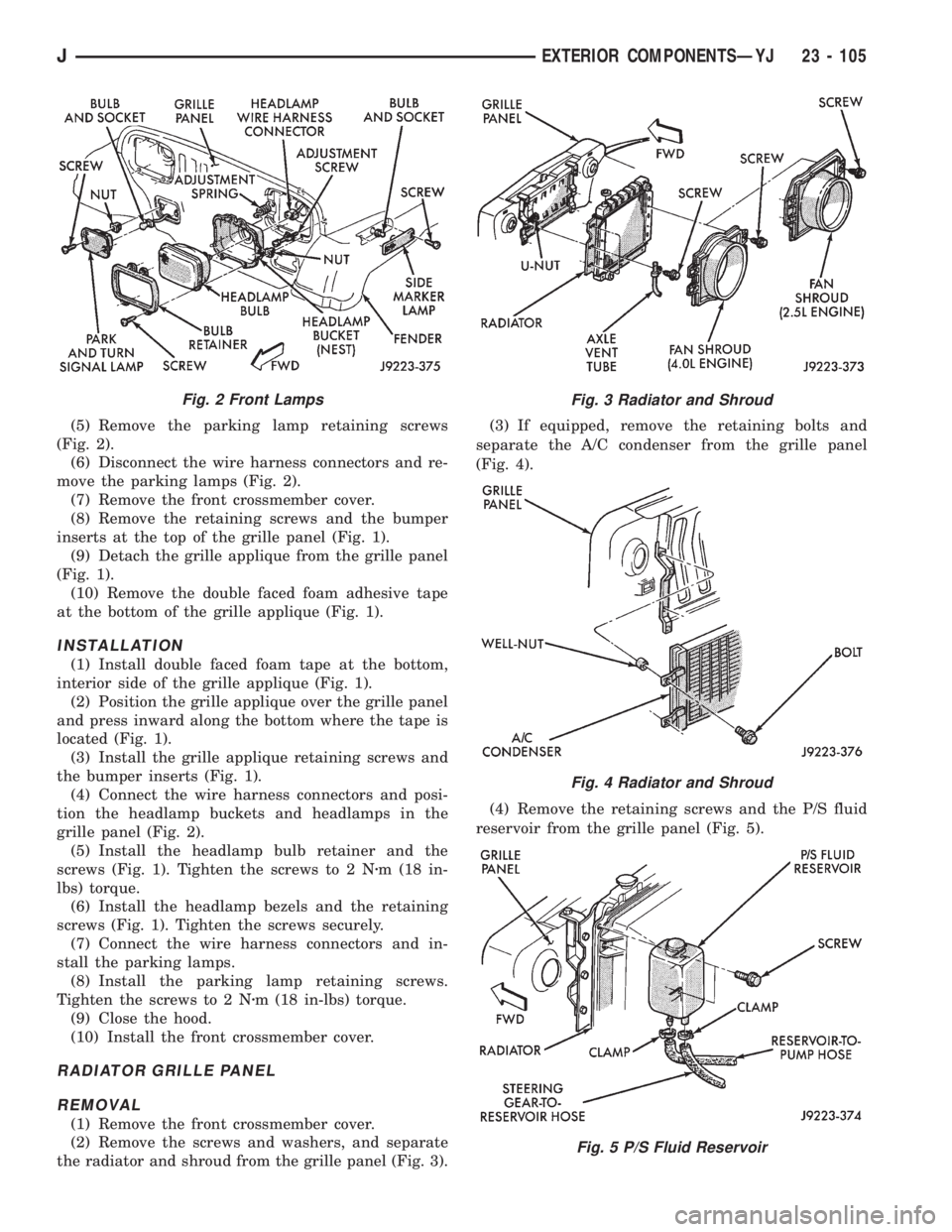
(5) Remove the parking lamp retaining screws
(Fig. 2).
(6) Disconnect the wire harness connectors and re-
move the parking lamps (Fig. 2).
(7) Remove the front crossmember cover.
(8) Remove the retaining screws and the bumper
inserts at the top of the grille panel (Fig. 1).
(9) Detach the grille applique from the grille panel
(Fig. 1).
(10) Remove the double faced foam adhesive tape
at the bottom of the grille applique (Fig. 1).
INSTALLATION
(1) Install double faced foam tape at the bottom,
interior side of the grille applique (Fig. 1).
(2) Position the grille applique over the grille panel
and press inward along the bottom where the tape is
located (Fig. 1).
(3) Install the grille applique retaining screws and
the bumper inserts (Fig. 1).
(4) Connect the wire harness connectors and posi-
tion the headlamp buckets and headlamps in the
grille panel (Fig. 2).
(5) Install the headlamp bulb retainer and the
screws (Fig. 1). Tighten the screws to 2 Nzm (18 in-
lbs) torque.
(6) Install the headlamp bezels and the retaining
screws (Fig. 1). Tighten the screws securely.
(7) Connect the wire harness connectors and in-
stall the parking lamps.
(8) Install the parking lamp retaining screws.
Tighten the screws to 2 Nzm (18 in-lbs) torque.
(9) Close the hood.
(10) Install the front crossmember cover.
RADIATOR GRILLE PANEL
REMOVAL
(1) Remove the front crossmember cover.
(2) Remove the screws and washers, and separate
the radiator and shroud from the grille panel (Fig. 3).(3) If equipped, remove the retaining bolts and
separate the A/C condenser from the grille panel
(Fig. 4).
(4) Remove the retaining screws and the P/S fluid
reservoir from the grille panel (Fig. 5).
Fig. 2 Front LampsFig. 3 Radiator and Shroud
Fig. 4 Radiator and Shroud
Fig. 5 P/S Fluid Reservoir
JEXTERIOR COMPONENTSÐYJ 23 - 105
Page 2031 of 2158
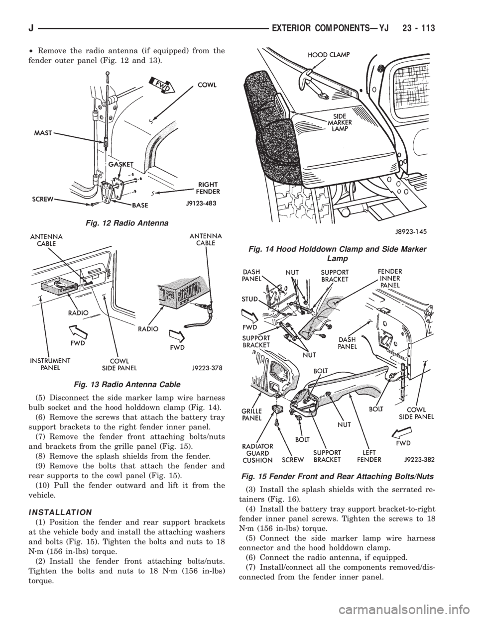
²Remove the radio antenna (if equipped) from the
fender outer panel (Fig. 12 and 13).
(5) Disconnect the side marker lamp wire harness
bulb socket and the hood holddown clamp (Fig. 14).
(6) Remove the screws that attach the battery tray
support brackets to the right fender inner panel.
(7) Remove the fender front attaching bolts/nuts
and brackets from the grille panel (Fig. 15).
(8) Remove the splash shields from the fender.
(9) Remove the bolts that attach the fender and
rear supports to the cowl panel (Fig. 15).
(10) Pull the fender outward and lift it from the
vehicle.
INSTALLATION
(1) Position the fender and rear support brackets
at the vehicle body and install the attaching washers
and bolts (Fig. 15). Tighten the bolts and nuts to 18
Nzm (156 in-lbs) torque.
(2) Install the fender front attaching bolts/nuts.
Tighten the bolts and nuts to 18 Nzm (156 in-lbs)
torque.(3) Install the splash shields with the serrated re-
tainers (Fig. 16).
(4) Install the battery tray support bracket-to-right
fender inner panel screws. Tighten the screws to 18
Nzm (156 in-lbs) torque.
(5) Connect the side marker lamp wire harness
connector and the hood holddown clamp.
(6) Connect the radio antenna, if equipped.
(7) Install/connect all the components removed/dis-
connected from the fender inner panel.
Fig. 12 Radio Antenna
Fig. 13 Radio Antenna Cable
Fig. 14 Hood Holddown Clamp and Side Marker
Lamp
Fig. 15 Fender Front and Rear Attaching Bolts/Nuts
JEXTERIOR COMPONENTSÐYJ 23 - 113
Page 2032 of 2158
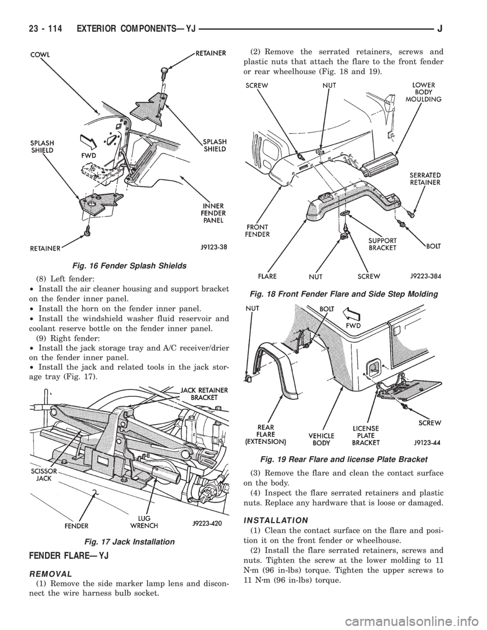
(8) Left fender:
²Install the air cleaner housing and support bracket
on the fender inner panel.
²Install the horn on the fender inner panel.
²Install the windshield washer fluid reservoir and
coolant reserve bottle on the fender inner panel.
(9) Right fender:
²Install the jack storage tray and A/C receiver/drier
on the fender inner panel.
²Install the jack and related tools in the jack stor-
age tray (Fig. 17).
FENDER FLAREÐYJ
REMOVAL
(1) Remove the side marker lamp lens and discon-
nect the wire harness bulb socket.(2) Remove the serrated retainers, screws and
plastic nuts that attach the flare to the front fender
or rear wheelhouse (Fig. 18 and 19).
(3) Remove the flare and clean the contact surface
on the body.
(4) Inspect the flare serrated retainers and plastic
nuts. Replace any hardware that is loose or damaged.
INSTALLATION
(1) Clean the contact surface on the flare and posi-
tion it on the front fender or wheelhouse.
(2) Install the flare serrated retainers, screws and
nuts. Tighten the screw at the lower molding to 11
Nzm (96 in-lbs) torque. Tighten the upper screws to
11 Nzm (96 in-lbs) torque.
Fig. 16 Fender Splash Shields
Fig. 17 Jack Installation
Fig. 18 Front Fender Flare and Side Step Molding
Fig. 19 Rear Flare and license Plate Bracket
23 - 114 EXTERIOR COMPONENTSÐYJJ
Page 2035 of 2158
The work area temperature should be between
18ÉC (65ÉF) and 32ÉC (90ÉF).A tape stripe/decal
should not be replaced if the work area temper-
ature is less than 18ÉC (65ÉF).
The following equipment and material are neces-
sary for body stripe/decal removal and installation:
²Commercial tape stripe/decal removal solution.
²Commercial adhesive removal solution.
²Liquid dish detergent (for the wetting solution).
²Mixture of wetting solution.
²Commercial wax and silicone removal solution.
²Isopropyl (rubbing) alcohol.
²Small squeegee (plastic or hard rubber).
²Water bucket and sponge.
²Clean wiping rags or paper towels.
²Heat gun (or infra-red heat bulb).
²Wax pencil.
²Sharp knife, single edge razor blade or X-acto
knife.
²Pair of scissors.
²Needle or pin.
A wetting solution assures a better bond between
the painted surface of the body and the tape stripe/
decal. Prepare a supply of wetting solution by mixing
two or three teaspoons of dish detergent with 1 gal-
lon of water.Do not use soap.
Too much detergent will reduce the effective-
ness of the mixture.
REMOVAL
The key to successful tape stripe/decal re-
moval is to apply heat to area and slowly peel
stripe/decal from panel.
(1) Clean the repaired surface, adjacent panels and
door openings as necessary.
(2) Start at one end of the tape stripe/decal and
apply heat with a heat gun. Slowly peel the stripe/
decal from the panel by pulling it back.Do not pull
the tape stripe/decal outward from the panel.
WARNING: USE THE TAPE STRIPE/DECAL RE-
MOVAL SOLUTION IN A WELL-VENTILATED AREA
ONLY.
(3) A commercial tape stripe/decal removal solution
can be used for stripe/decal removal at areas where a
heat gun is ineffective:
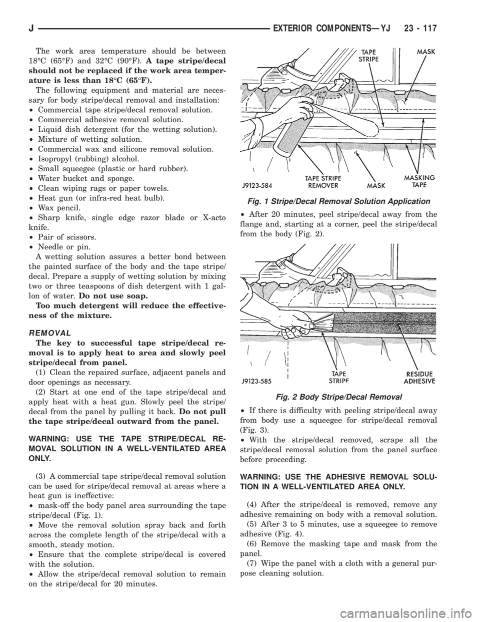
²mask-off the body panel area surrounding the tape
stripe/decal (Fig. 1).
²Move the removal solution spray back and forth
across the complete length of the stripe/decal with a
smooth, steady motion.
²Ensure that the complete stripe/decal is covered
with the solution.
²Allow the stripe/decal removal solution to remain
on the stripe/decal for 20 minutes.²After 20 minutes, peel stripe/decal away from the
flange and, starting at a corner, peel the stripe/decal
from the body (Fig. 2).
²If there is difficulty with peeling stripe/decal away
from body use a squeegee for stripe/decal removal
(Fig. 3).
²With the stripe/decal removed, scrape all the
stripe/decal removal solution from the panel surface
before proceeding.
WARNING: USE THE ADHESIVE REMOVAL SOLU-
TION IN A WELL-VENTILATED AREA ONLY.
(4) After the stripe/decal is removed, remove any
adhesive remaining on body with a removal solution.
(5) After 3 to 5 minutes, use a squeegee to remove
adhesive (Fig. 4).
(6) Remove the masking tape and mask from the
panel.
(7) Wipe the panel with a cloth with a general pur-
pose cleaning solution.
Fig. 1 Stripe/Decal Removal Solution Application
Fig. 2 Body Stripe/Decal Removal
JEXTERIOR COMPONENTSÐYJ 23 - 117
Page 2069 of 2158
INTERIOR COMPONENTS
INDEX
page page
Add-A-TrunkÐYJ........................ 157
Bucket SeatsÐYJ........................ 153
CarpetÐYJ............................. 156
Floor ConsolesÐYJ...................... 155
Front Shoulder BeltsÐYJ.................. 154
Glove BoxÐYJ.......................... 152
Instrument Cluster and Gauge HousingsÐYJ.... 151Instrument Cluster BezelÐYJ............... 151
Instrument Panel ComponentsÐYJ........... 152
Instrument PanelÐYJ..................... 151
Rear Bench SeatÐYJ..................... 153
Rear Shoulder BeltsÐYJ................... 154
SeatsÐYJ............................. 153
SunvisorsÐYJ.......................... 155
INSTRUMENT PANELÐYJ
The instrument panel is constructed of sheet metal
and is attached to cowl panel with screws. The in-
strument panel and defroster grille pad is attached
to the instrument panel with screws.
INSTRUMENT CLUSTER AND GAUGE HOUSINGSÐ
YJ
REMOVAL
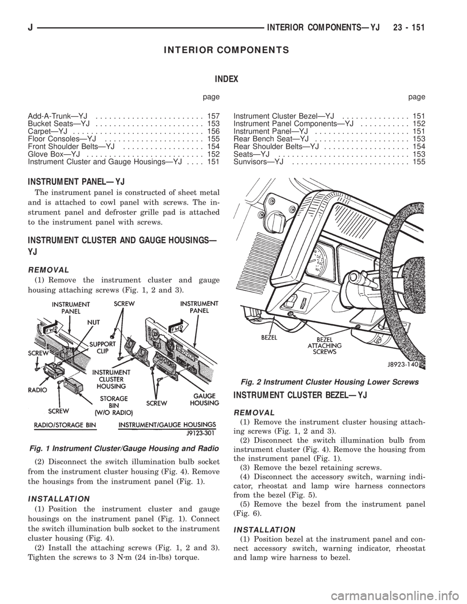
(1) Remove the instrument cluster and gauge
housing attaching screws (Fig. 1, 2 and 3).
(2) Disconnect the switch illumination bulb socket
from the instrument cluster housing (Fig. 4). Remove
the housings from the instrument panel (Fig. 1).
INSTALLATION
(1) Position the instrument cluster and gauge
housings on the instrument panel (Fig. 1). Connect
the switch illumination bulb socket to the instrument
cluster housing (Fig. 4).
(2) Install the attaching screws (Fig. 1, 2 and 3).
Tighten the screws to 3 Nzm (24 in-lbs) torque.
INSTRUMENT CLUSTER BEZELÐYJ
REMOVAL
(1) Remove the instrument cluster housing attach-
ing screws (Fig. 1, 2 and 3).
(2) Disconnect the switch illumination bulb from
instrument cluster (Fig. 4). Remove the housing from
the instrument panel (Fig. 1).
(3) Remove the bezel retaining screws.
(4) Disconnect the accessory switch, warning indi-
cator, rheostat and lamp wire harness connectors
from the bezel (Fig. 5).
(5) Remove the bezel from the instrument panel
(Fig. 6).
INSTALLATION
(1) Position bezel at the instrument panel and con-
nect accessory switch, warning indicator, rheostat
and lamp wire harness to bezel.
Fig. 1 Instrument Cluster/Gauge Housing and Radio
Fig. 2 Instrument Cluster Housing Lower Screws
JINTERIOR COMPONENTSÐYJ 23 - 151
Page 2070 of 2158
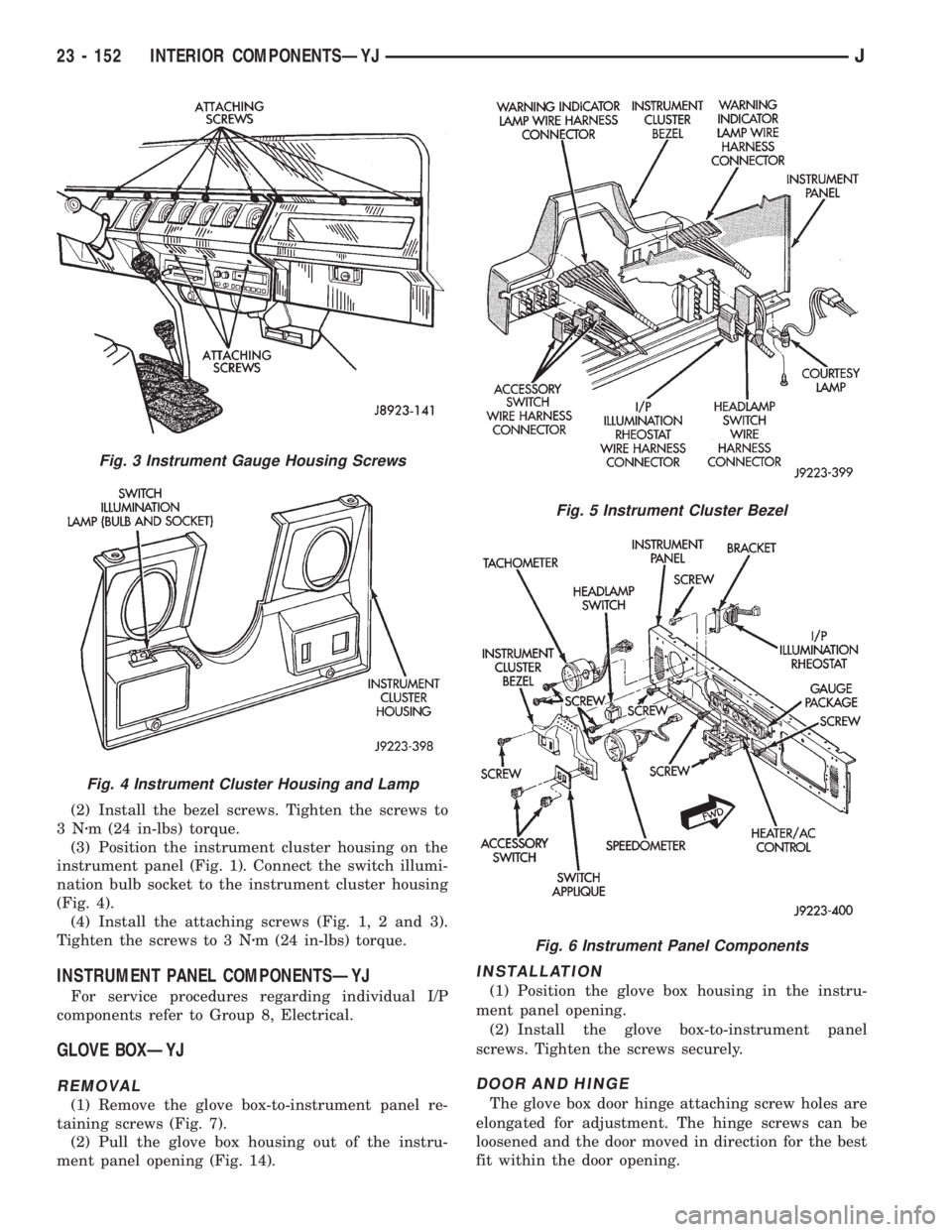
(2) Install the bezel screws. Tighten the screws to
3Nzm (24 in-lbs) torque.
(3) Position the instrument cluster housing on the
instrument panel (Fig. 1). Connect the switch illumi-
nation bulb socket to the instrument cluster housing
(Fig. 4).
(4) Install the attaching screws (Fig. 1, 2 and 3).
Tighten the screws to 3 Nzm (24 in-lbs) torque.
INSTRUMENT PANEL COMPONENTSÐYJ
For service procedures regarding individual I/P
components refer to Group 8, Electrical.
GLOVE BOXÐYJ
REMOVAL
(1) Remove the glove box-to-instrument panel re-
taining screws (Fig. 7).
(2) Pull the glove box housing out of the instru-
ment panel opening (Fig. 14).
INSTALLATION
(1) Position the glove box housing in the instru-
ment panel opening.
(2) Install the glove box-to-instrument panel
screws. Tighten the screws securely.
DOOR AND HINGE
The glove box door hinge attaching screw holes are
elongated for adjustment. The hinge screws can be
loosened and the door moved in direction for the best
fit within the door opening.
Fig. 3 Instrument Gauge Housing Screws
Fig. 4 Instrument Cluster Housing and Lamp
Fig. 5 Instrument Cluster Bezel
Fig. 6 Instrument Panel Components
23 - 152 INTERIOR COMPONENTSÐYJJ