1995 JEEP XJ weight
[x] Cancel search: weightPage 1670 of 2158
bind if misalignment occurs. Remove and repo-
sition governor body if necessary.
(9) Verify that shaft bore in governor body and out-
put shaft are aligned.
(10) Verify that governor valve will be indexed
with spotface in output shaft. Reposition valve, shaft
and body if necessary.
(11) Install an E-clip on one end of governor valve
shaft. Be sure rounded side of E-clip is facing out
(away from weight).
(12) Insert governor valve shaft through governor
weight. Be sure shaft slides freely in bore.
(13) Install governor valve on shaft and in gover-
nor body bore.
(14) Install remaining E-clip on governor valve
shaft. Be sure rounded side of E-clip is facing out
(away from valve).
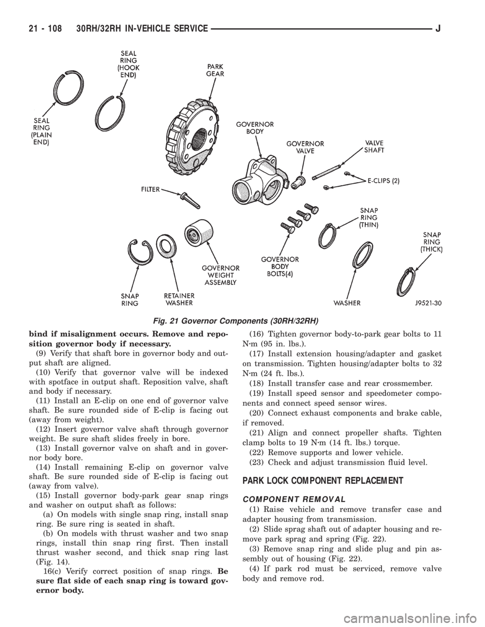
(15) Install governor body-park gear snap rings
and washer on output shaft as follows:
(a) On models with single snap ring, install snap
ring. Be sure ring is seated in shaft.
(b) On models with thrust washer and two snap
rings, install thin snap ring first. Then install
thrust washer second, and thick snap ring last
(Fig. 14).
16(c) Verify correct position of snap rings.Be
sure flat side of each snap ring is toward gov-
ernor body.(16) Tighten governor body-to-park gear bolts to 11
Nzm (95 in. lbs.).
(17) Install extension housing/adapter and gasket
on transmission. Tighten housing/adapter bolts to 32
Nzm (24 ft. lbs.).
(18) Install transfer case and rear crossmember.
(19) Install speed sensor and speedometer compo-
nents and connect speed sensor wires.
(20) Connect exhaust components and brake cable,
if removed.
(21) Align and connect propeller shafts. Tighten
clamp bolts to 19 Nzm (14 ft. lbs.) torque.
(22) Remove supports and lower vehicle.
(23) Check and adjust transmission fluid level.
PARK LOCK COMPONENT REPLACEMENT
COMPONENT REMOVAL
(1) Raise vehicle and remove transfer case and
adapter housing from transmission.
(2) Slide sprag shaft out of adapter housing and re-
move park sprag and spring (Fig. 22).
(3) Remove snap ring and slide plug and pin as-
sembly out of housing (Fig. 22).
(4) If park rod must be serviced, remove valve
body and remove rod.
Fig. 21 Governor Components (30RH/32RH)
21 - 108 30RH/32RH IN-VEHICLE SERVICEJ
Page 1683 of 2158
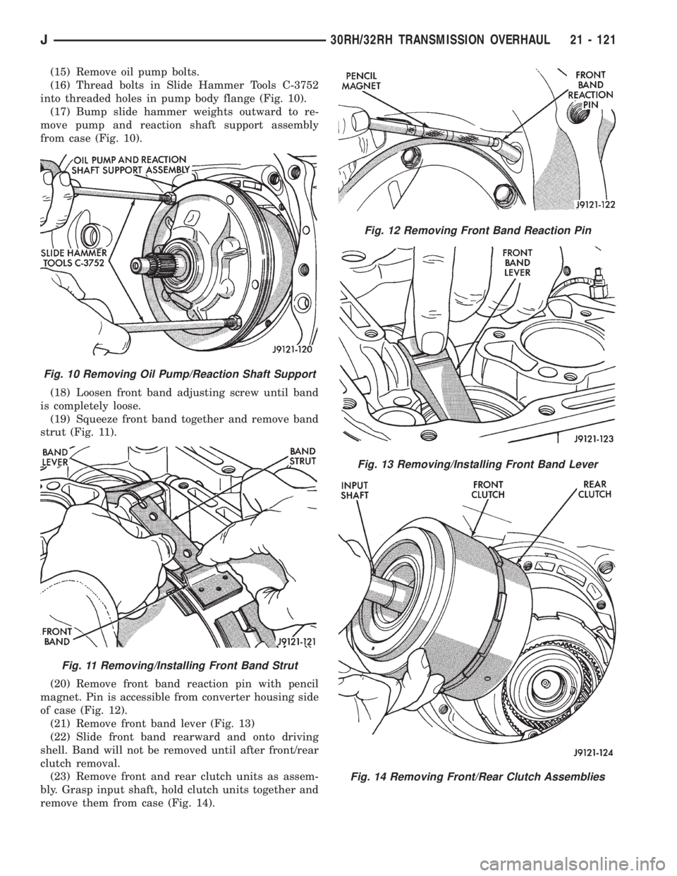
(15) Remove oil pump bolts.
(16) Thread bolts in Slide Hammer Tools C-3752
into threaded holes in pump body flange (Fig. 10).
(17) Bump slide hammer weights outward to re-
move pump and reaction shaft support assembly
from case (Fig. 10).
(18) Loosen front band adjusting screw until band
is completely loose.
(19) Squeeze front band together and remove band
strut (Fig. 11).
(20) Remove front band reaction pin with pencil
magnet. Pin is accessible from converter housing side
of case (Fig. 12).
(21) Remove front band lever (Fig. 13)
(22) Slide front band rearward and onto driving
shell. Band will not be removed until after front/rear
clutch removal.
(23) Remove front and rear clutch units as assem-
bly. Grasp input shaft, hold clutch units together and
remove them from case (Fig. 14).
Fig. 10 Removing Oil Pump/Reaction Shaft Support
Fig. 11 Removing/Installing Front Band Strut
Fig. 12 Removing Front Band Reaction Pin
Fig. 13 Removing/Installing Front Band Lever
Fig. 14 Removing Front/Rear Clutch Assemblies
J30RH/32RH TRANSMISSION OVERHAUL 21 - 121
Page 1689 of 2158
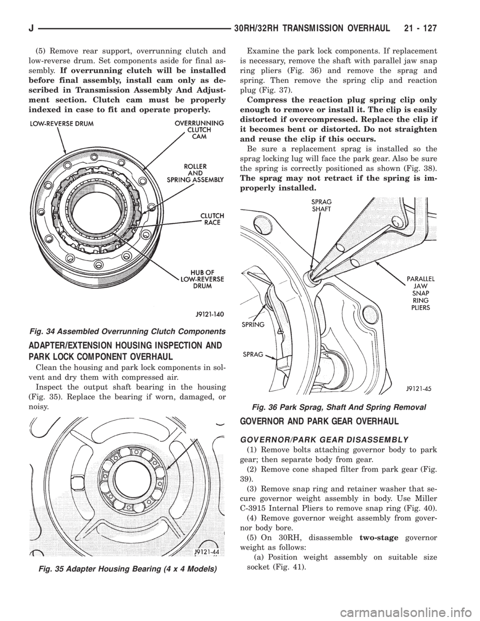
(5) Remove rear support, overrunning clutch and
low-reverse drum. Set components aside for final as-
sembly.If overrunning clutch will be installed
before final assembly, install cam only as de-
scribed in Transmission Assembly And Adjust-
ment section. Clutch cam must be properly
indexed in case to fit and operate properly.
ADAPTER/EXTENSION HOUSING INSPECTION AND
PARK LOCK COMPONENT OVERHAUL
Clean the housing and park lock components in sol-
vent and dry them with compressed air.
Inspect the output shaft bearing in the housing
(Fig. 35). Replace the bearing if worn, damaged, or
noisy.Examine the park lock components. If replacement
is necessary, remove the shaft with parallel jaw snap
ring pliers (Fig. 36) and remove the sprag and
spring. Then remove the spring clip and reaction
plug (Fig. 37).
Compress the reaction plug spring clip only
enough to remove or install it. The clip is easily
distorted if overcompressed. Replace the clip if
it becomes bent or distorted. Do not straighten
and reuse the clip if this occurs.
Be sure a replacement sprag is installed so the
sprag locking lug will face the park gear. Also be sure
the spring is correctly positioned as shown (Fig. 38).
The sprag may not retract if the spring is im-
properly installed.
GOVERNOR AND PARK GEAR OVERHAUL
GOVERNOR/PARK GEAR DISASSEMBLY
(1) Remove bolts attaching governor body to park
gear; then separate body from gear.
(2) Remove cone shaped filter from park gear (Fig.
39).
(3) Remove snap ring and retainer washer that se-
cure governor weight assembly in body. Use Miller
C-3915 Internal Pliers to remove snap ring (Fig. 40).
(4) Remove governor weight assembly from gover-
nor body bore.
(5) On 30RH, disassembletwo-stagegovernor
weight as follows:
(a) Position weight assembly on suitable size
socket (Fig. 41).
Fig. 34 Assembled Overrunning Clutch Components
Fig. 35 Adapter Housing Bearing (4 x 4 Models)
Fig. 36 Park Sprag, Shaft And Spring Removal
J30RH/32RH TRANSMISSION OVERHAUL 21 - 127
Page 1690 of 2158
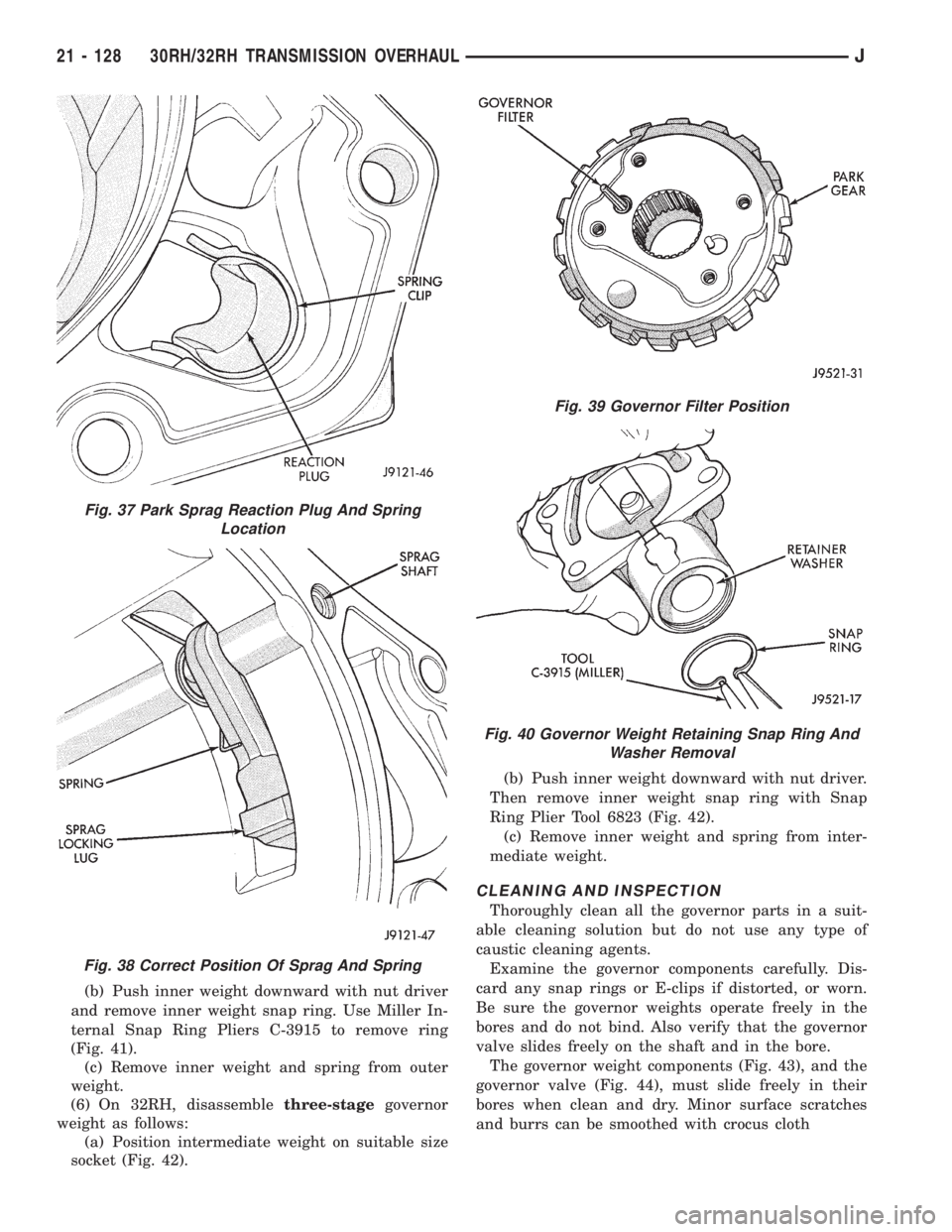
(b) Push inner weight downward with nut driver
and remove inner weight snap ring. Use Miller In-
ternal Snap Ring Pliers C-3915 to remove ring
(Fig. 41).
(c) Remove inner weight and spring from outer
weight.
(6) On 32RH, disassemblethree-stagegovernor
weight as follows:
(a) Position intermediate weight on suitable size
socket (Fig. 42).(b) Push inner weight downward with nut driver.
Then remove inner weight snap ring with Snap
Ring Plier Tool 6823 (Fig. 42).
(c) Remove inner weight and spring from inter-
mediate weight.
CLEANING AND INSPECTION
Thoroughly clean all the governor parts in a suit-
able cleaning solution but do not use any type of
caustic cleaning agents.
Examine the governor components carefully. Dis-
card any snap rings or E-clips if distorted, or worn.
Be sure the governor weights operate freely in the
bores and do not bind. Also verify that the governor
valve slides freely on the shaft and in the bore.
The governor weight components (Fig. 43), and the
governor valve (Fig. 44), must slide freely in their
bores when clean and dry. Minor surface scratches
and burrs can be smoothed with crocus cloth
Fig. 37 Park Sprag Reaction Plug And Spring
Location
Fig. 38 Correct Position Of Sprag And Spring
Fig. 39 Governor Filter Position
Fig. 40 Governor Weight Retaining Snap Ring And
Washer Removal
21 - 128 30RH/32RH TRANSMISSION OVERHAULJ
Page 1691 of 2158
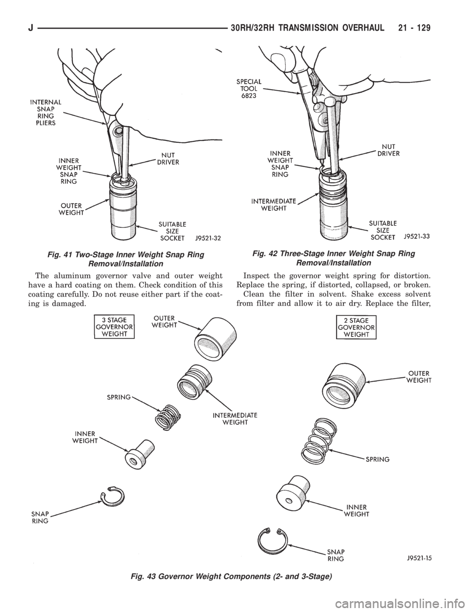
The aluminum governor valve and outer weight
have a hard coating on them. Check condition of this
coating carefully. Do not reuse either part if the coat-
ing is damaged.Inspect the governor weight spring for distortion.
Replace the spring, if distorted, collapsed, or broken.
Clean the filter in solvent. Shake excess solvent
from filter and allow it to air dry. Replace the filter,
Fig. 41 Two-Stage Inner Weight Snap Ring
Removal/InstallationFig. 42 Three-Stage Inner Weight Snap Ring
Removal/Installation
Fig. 43 Governor Weight Components (2- and 3-Stage)
J30RH/32RH TRANSMISSION OVERHAUL 21 - 129
Page 1693 of 2158
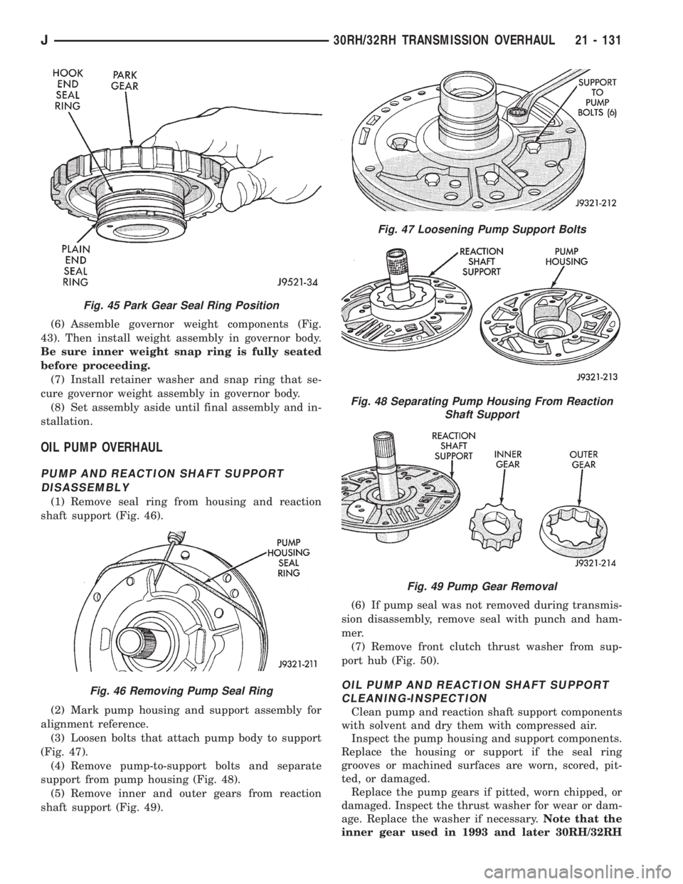
(6) Assemble governor weight components (Fig.
43). Then install weight assembly in governor body.
Be sure inner weight snap ring is fully seated
before proceeding.
(7) Install retainer washer and snap ring that se-
cure governor weight assembly in governor body.
(8) Set assembly aside until final assembly and in-
stallation.
OIL PUMP OVERHAUL
PUMP AND REACTION SHAFT SUPPORT
DISASSEMBLY
(1) Remove seal ring from housing and reaction
shaft support (Fig. 46).
(2) Mark pump housing and support assembly for
alignment reference.
(3) Loosen bolts that attach pump body to support
(Fig. 47).
(4) Remove pump-to-support bolts and separate
support from pump housing (Fig. 48).
(5) Remove inner and outer gears from reaction
shaft support (Fig. 49).(6) If pump seal was not removed during transmis-
sion disassembly, remove seal with punch and ham-
mer.
(7) Remove front clutch thrust washer from sup-
port hub (Fig. 50).
OIL PUMP AND REACTION SHAFT SUPPORT
CLEANING-INSPECTION
Clean pump and reaction shaft support components
with solvent and dry them with compressed air.
Inspect the pump housing and support components.
Replace the housing or support if the seal ring
grooves or machined surfaces are worn, scored, pit-
ted, or damaged.
Replace the pump gears if pitted, worn chipped, or
damaged. Inspect the thrust washer for wear or dam-
age. Replace the washer if necessary.Note that the
inner gear used in 1993 and later 30RH/32RH
Fig. 45 Park Gear Seal Ring Position
Fig. 46 Removing Pump Seal Ring
Fig. 47 Loosening Pump Support Bolts
Fig. 48 Separating Pump Housing From Reaction
Shaft Support
Fig. 49 Pump Gear Removal
J30RH/32RH TRANSMISSION OVERHAUL 21 - 131
Page 1773 of 2158
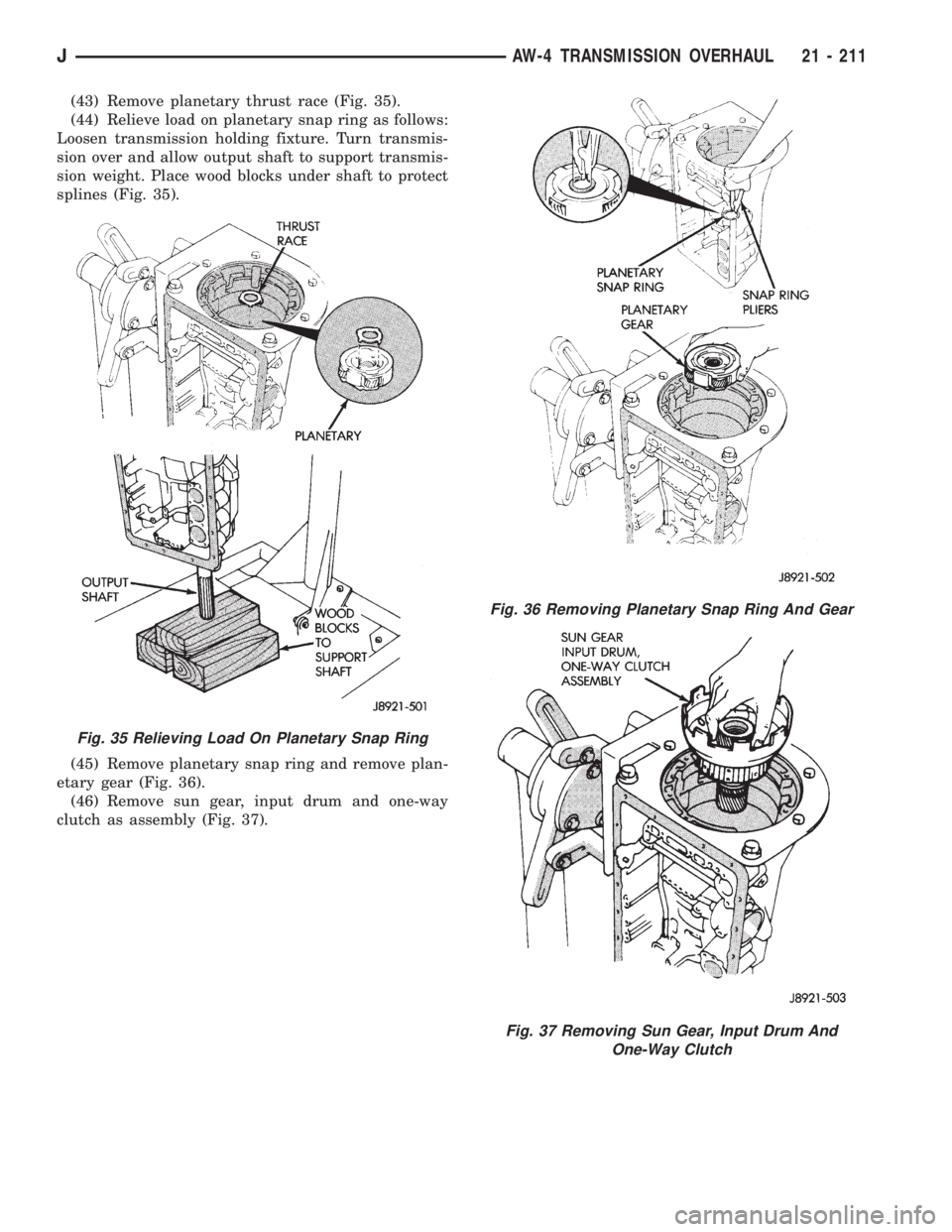
(43) Remove planetary thrust race (Fig. 35).
(44) Relieve load on planetary snap ring as follows:
Loosen transmission holding fixture. Turn transmis-
sion over and allow output shaft to support transmis-
sion weight. Place wood blocks under shaft to protect
splines (Fig. 35).
(45) Remove planetary snap ring and remove plan-
etary gear (Fig. 36).
(46) Remove sun gear, input drum and one-way
clutch as assembly (Fig. 37).
Fig. 35 Relieving Load On Planetary Snap Ring
Fig. 36 Removing Planetary Snap Ring And Gear
Fig. 37 Removing Sun Gear, Input Drum And
One-Way Clutch
JAW-4 TRANSMISSION OVERHAUL 21 - 211
Page 1912 of 2158
WHEELS
GENERAL INFORMATION
Original equipment wheels are designed for the
specified Maximum Vehicle Capacity.
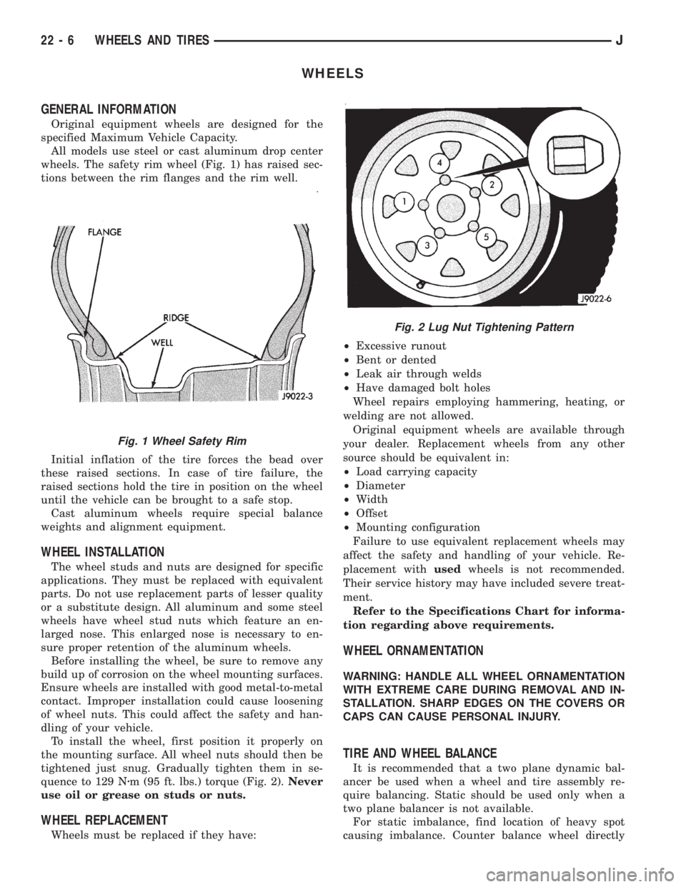
All models use steel or cast aluminum drop center
wheels. The safety rim wheel (Fig. 1) has raised sec-
tions between the rim flanges and the rim well.
Initial inflation of the tire forces the bead over
these raised sections. In case of tire failure, the
raised sections hold the tire in position on the wheel
until the vehicle can be brought to a safe stop.
Cast aluminum wheels require special balance
weights and alignment equipment.
WHEEL INSTALLATION
The wheel studs and nuts are designed for specific
applications. They must be replaced with equivalent
parts. Do not use replacement parts of lesser quality
or a substitute design. All aluminum and some steel
wheels have wheel stud nuts which feature an en-
larged nose. This enlarged nose is necessary to en-
sure proper retention of the aluminum wheels.
Before installing the wheel, be sure to remove any
build up of corrosion on the wheel mounting surfaces.
Ensure wheels are installed with good metal-to-metal
contact. Improper installation could cause loosening
of wheel nuts. This could affect the safety and han-
dling of your vehicle.
To install the wheel, first position it properly on
the mounting surface. All wheel nuts should then be
tightened just snug. Gradually tighten them in se-
quence to 129 Nzm (95 ft. lbs.) torque (Fig. 2).Never
use oil or grease on studs or nuts.
WHEEL REPLACEMENT
Wheels must be replaced if they have:²Excessive runout
²Bent or dented
²Leak air through welds
²Have damaged bolt holes
Wheel repairs employing hammering, heating, or
welding are not allowed.
Original equipment wheels are available through
your dealer. Replacement wheels from any other
source should be equivalent in:
²Load carrying capacity
²Diameter
²Width
²Offset
²Mounting configuration
Failure to use equivalent replacement wheels may
affect the safety and handling of your vehicle. Re-
placement withusedwheels is not recommended.
Their service history may have included severe treat-
ment.
Refer to the Specifications Chart for informa-
tion regarding above requirements.
WHEEL ORNAMENTATION
WARNING: HANDLE ALL WHEEL ORNAMENTATION
WITH EXTREME CARE DURING REMOVAL AND IN-
STALLATION. SHARP EDGES ON THE COVERS OR
CAPS CAN CAUSE PERSONAL INJURY.
TIRE AND WHEEL BALANCE
It is recommended that a two plane dynamic bal-
ancer be used when a wheel and tire assembly re-
quire balancing. Static should be used only when a
two plane balancer is not available.
For static imbalance, find location of heavy spot
causing imbalance. Counter balance wheel directly
Fig. 1 Wheel Safety Rim
Fig. 2 Lug Nut Tightening Pattern
22 - 6 WHEELS AND TIRESJ