1995 JEEP XJ charging
[x] Cancel search: chargingPage 857 of 2158

CHARGING SYSTEM
CHARGING SYSTEM
The charging system is an integral part of the bat-
tery and starting systems. Because all these systems
work in conjunction, diagnose and test them together.
Circuit A11 connects to the generator output termi-
nal and splices to fuse 1 and fuse 9 in the Power Dis-
tribution Center (PDC). Circuit A0 connects the
battery to the PDC. Circuit Z0 provides ground for
the generator.
When the ignition switch is in either the START or
RUN positions, it connects circuit A1 from fuse 6 in
the PDC to circuit A21. Circuit A21 splices to supply
current to the coil side of the Automatic Shut Down
(ASD) relay. The Powertrain Control Module (PCM)
provides ground for the relay on circuit K51. Circuit
K51 connects to cavity 51 of the PCM.
When the PCM grounds the ASD relay, contacts in-
side the relay close and connect circuit A18 from fuse
14 in the PDC to circuit A142. Circuit A142 splices to
the generator field terminal.
The PCM has an internal voltage regulator that
controls generator output. The PCM controls the gen-
erator field on circuit K20. Circuit K20 connects to
PCM cavity 20.When the engine operates and there is current in
the generator field, the generator produces a B+ volt-
age. The generator supplies B+ voltage to the battery
through the A11 and A0 circuits.
HELPFUL INFORMATION
²Circuit A14 from fuse 2 in the PDC supplies volt-
age to PDC fuse 14.
²The ignition switch also connects circuit A1 with
circuits A41, A38, and A48.
²Circuit A21 also powers the coil side of the fuel
pump relay.
²The ASD relay supplies battery voltage for the fuel
injectors, ignition coil, and the heated oxygen sensor.
The fuel pump relay powers the fuel pump module.
²Circuit K51 also provides ground for the coil side
of the fuel pump relay.
DIAGRAM INDEX
Component Page
Battery...............................8W-20-2
PDC Fuse 1............................8W-20-2
PDC Fuse 9............................8W-20-2
Generator..............................8W-20-2
Powertrain Control Module..................8W-20-2
J8W-20 CHARGING SYSTEMÐXJ-RHD 8W - 20 - 1
Page 1094 of 2158
WIRING DIAGRAMS
CONTENTS
page page
8W-01 GENERAL INFORMATIONÐWIRING
DIAGRAMS...................... 8W-01-1
8W-10 FUSE/FUSE BLOCK........... 8W-10-1
8W-11 POWER DISTRIBUTION........ 8W-11-1
8W-15 GROUND DISTRIBUTION....... 8W-15-1
8W-20 CHARGING SYSTEM.......... 8W-20-1
8W-21 STARTING SYSTEM........... 8W-21-1
8W-30 FUEL/IGNITION.............. 8W-30-1
8W-31 TRANSMISSION CONTROLS.... 8W-31-1
8W-32 ANTI-LOCK BRAKES.......... 8W-32-1
8W-40 INSTRUMENT CLUSTER....... 8W-40-1
8W-41 HORN/CIGAR LIGHTER........ 8W-41-18W-42 AIR CONDITIONING/HEATER.... 8W-42-1
8W-44 INTERIOR LIGHTING.......... 8W-44-1
8W-47 AUDIO SYSTEM.............. 8W-47-1
8W-48 HEATED REAR WINDOW....... 8W-48-1
8W-50 FRONT LIGHTING............ 8W-50-1
8W-51 REAR LIGHTING............. 8W-51-1
8W-52 TURN SIGNALS.............. 8W-52-1
8W-53 WIPERS.................... 8W-53-1
8W-70 SPLICE INFORMATION........ 8W-70-1
8W-80 CONNECTOR PIN OUTS....... 8W-80-1
8W-90 CONNECTOR LOCATIONS...... 8W-90-1
8W-95 SPLICE LOCATIONS........... 8W-95-1
HOW TO USE THIS GROUP
The purpose of this group is to show the electrical
circuits in a clear, simple fashion and to make trou-
bleshooting easier. Components that work together
are shown together. All electrical components used in
a specific system are shown on one diagram. The feed
for a system is shown at the top of the page. All
wires, connectors, splices, and components are shown
in the flow of current to the bottom of the page. Wir-
ing which is not part of the circuit represented is ref-
erenced to another page/section, where the complete
circuit is shown. In addition, all switches, compo-
nents, and modules are shown in theat rest posi-
tion with the doors closed and the key removed
from the ignition.
If a component is part of several different circuits,
it is shown in the diagram for each. For example, the
headlamp switch is the main part of the exterior
lighting, but it also affects the interior lighting and
the chime warning system.
It is important to realize that no attempt is
made on the diagrams to represent components
and wiring as they appear on the vehicle. For
example, a short piece of wire is treated the
same as a long one. In addition, switches and
other components are shown as simply as pos-
sible, with regard to function only.
The wiring diagram show circuits for all wheel-
bases. If there is a difference in systems or compo-
nents between wheel-bases, an identifier is placed
next to the component.
SECTION IDENTIFICATION
Sections in Group 8W are organized by sub-sys-
tems. The sections contain circuit operation descrip-
tions, helpful information, and system diagrams. The
intention is to organize information by system, con-
sistently from year to year.
CONNECTOR LOCATIONS
Section 8W-90 contains Connector Location illus-
trations. The illustrations contain the connector
number and component identification. Connector Lo-
cation charts in Section 8W-90 reference the illustra-
tion number for components and connectors.
Section 8W-80 shows each connector and the cir-
cuits involved with that connector. The connectors
are identified using the number on the Diagram
pages.
SPLICE LOCATIONS
Splice Location charts in Section 8W-70 show the
entire splice, and provide references to other sections
the splice serves.
Section 8W-95 contains illustrations that show the
general location of the splices in each harness. The
illustrations show the splice by number, and provide
a written location.
JWIRING DIAGRAMSÐÐYJ VEHICLES 8W - 1 - 1
Page 1118 of 2158
CHARGING SYSTEM
CHARGING SYSTEM
The charging system is an integral part of the bat-
tery and starting systems. Because all these systems
work in conjunction, diagnose and test them together.
Circuit A11 connects to the generator output termi-
nal and splices to fuse 2 and fuse 6 in the Power Dis-
tribution Center (PDC). Circuit A0 connects the
battery to the PDC.
Circuit Z0 provides ground for the generator. Cir-
cuit Z0 attaches to the right side rear of the engine.
When the ignition switch is in either the START or
RUN position, it connects circuit A1 from fuse 4 in
the PDC to circuit A21. Circuit A21 powers fuse 5 in
the fuse block. Circuit G50 from fuse 5 splices to
power the coil side of the Automatic Shut Down
(ASD) relay. The Powertrain Control Module (PCM)
provides ground for the relay on circuit K51. Circuit
K51 connects to cavity 51 of the PCM.
When the PCM grounds the ASD relay, contacts in-
side the relay close and connect circuit A14 from fuse
1 in the PDC to circuit A142. Circuit A142 splices to
the generator field terminal.
The PCM has an internal voltage regulator that
controls generator output. The PCM controls the gen-
erator field on circuit K20. Circuit K20 connects to
PCM cavity 20.When the engine operates and there is current in
the generator field, the generator produces a B+ volt-
age. The generator supplies B+ voltage to the battery
through the A11 and A0 circuits.
HELPFUL INFORMATION
²The ignition switch also connects circuit A1 with
circuits A41, A22, and A31.
²Circuit A21 also powers fuse 9 in the fuse block.
²Circuit G50 also powers the coil sides of the fuel
pump relay and the torque convertor clutch (TCC) re-
lay.
²The ASD relay supplies battery voltage for the fuel
injectors, ignition coil, and the heated oxygen sensor.
²Circuit K51 also provides ground for the coil side
of the fuel pump relay.
DIAGRAM INDEX
Component Page
Battery...............................8W-20-2
Fuse 2 (PDC)...........................8W-20-2
Fuse 6 (PDC)...........................8W-20-2
Generator..............................8W-20-2
Powertrain Control Module (PCM)..............8W-20-2
J8W-20 CHARGING SYSTEMÐYJ VEHICLES 8W - 20 - 1
Page 1421 of 2158
MULTI-PORT FUEL INJECTION (MFI)ÐCOMPONENT DESCRIPTION/SYSTEM
OPERATION
INDEX
page page
Air Cleaner.............................. 29
Air Conditioning (A/C) Clutch RelayÐPCM Output . 26
Air Conditioning (A/C) ControlsÐPCM Input...... 21
Auto Shutdown (ASD) RelayÐPCM Output...... 26
Automatic Shutdown (ASD) SenseÐPCM Input . . . 21
Battery VoltageÐPCM Input................. 21
Brake SwitchÐPCM Input................... 22
Camshaft Position SensorÐPCM Input......... 22
Crankshaft Position SensorÐPCM Input........ 22
Data Link ConnectorÐPCM Input............. 22
Data Link ConnectorÐPCM Output............ 27
EMR LampÐPCM Output................... 27
Engine Coolant Temperature SensorÐPCM Input . 23
Extended Idle SwitchÐPCM Input............. 23
Fuel InjectorsÐPCM Output................. 27
Fuel Pressure Regulator.................... 33
Fuel Pump RelayÐPCM Output.............. 27
Fuel Rail................................ 33
General Information....................... 19
Generator FieldÐPCM Output................ 27
Generator LampÐPCM Output............... 27
Idle Air Control (IAC) MotorÐPCM Output....... 27
Ignition Circuit SenseÐPCM Input............. 23
Ignition CoilÐPCM Output................... 28Intake Manifold Air Temperature SensorÐ
PCM Input............................. 22
Malfunction Indicator LampÐPCM Output....... 28
Manifold Absolute Pressure (MAP) SensorÐPCM
Input................................. 23
Open Loop/Closed Loop Modes of Operation..... 30
Oxygen (O2S) SensorÐPCM Input............ 24
Park/Neutral SwitchÐPCM Input.............. 24
Power Ground........................... 24
Power Steering Pressure SwitchÐPCM Input.... 24
Powertrain Control Module (PCM)............. 20
Radiator Fan RelayÐPCM Output............. 28
SCI ReceiveÐPCM Input................... 24
SCI TransmitÐPCM Output.................. 29
Sensor ReturnÐPCM Input.................. 25
Shift IndicatorÐPCM Output................. 29
Speed ControlÐPCM Input.................. 25
Speed ControlÐPCM Output................. 29
TachometerÐPCM Output................... 29
Throttle Body............................ 33
Throttle Position Sensor (TPS)ÐPCM Input...... 25
Torque Converter Clutch RelayÐPCM Output.... 29
Vehicle Speed SensorÐPCM Input............ 25
GENERAL INFORMATION
All 2.5L 4-cylinder and 4.0L 6-cylinder engines are
equipped with sequential Multi-Port Fuel Injection
(MFI). The MFI system provides precise air/fuel ra-
tios for all driving conditions.
The Powertrain Control Module (PCM) operates
the fuel system. The PCM was formerly referred to
as the SBEC or engine controller. The PCM is a pre-
programmed, dual microprocessor digital computer. It
regulates ignition timing, air-fuel ratio, emission con-
trol devices, charging system, speed control, air con-
ditioning compressor clutch engagement and idle
speed. The PCM can adapt its programming to meet
changing operating conditions.
Powertrain Control Module (PCM) Inputsrep-
resent the instantaneous engine operating conditions.
Air-fuel mixture and ignition timing calibrations for
various driving and atmospheric conditions are pre-
programmed into the PCM. The PCM monitors and
analyzes various inputs. It then computes engine fuel
and ignition timing requirements based on these in-
puts. Fuel delivery control and ignition timing will
then be adjusted accordingly.
Other inputs to the PCM are provided by the brake
light switch, air conditioning select switch and the
speed control switches. All inputs to the PCM are
converted into signals.
Electrically operated fuel injectors spray fuel inprecise metered amounts into the intake port directly
above the intake valve. The injectors are fired in a
specific sequence by the PCM. The PCM maintains
an air/fuel ratio of 14.7 to 1 by constantly adjusting
injector pulse width. Injector pulse width is the
length of time that the injector opens and sprays fuel
into the chamber. The PCM adjusts injector pulse
width by opening and closing the ground path to the
injector.
Manifold absolute pressure (air density) and engine
rpm (speed) are the primary inputs that determine
fuel injector pulse width. The PCM also monitors
other inputs when adjusting air-fuel ratio.
Inputs That Effect Fuel Injector Pulse Width:
²Exhaust gas oxygen content
²Engine coolant temperature
²Manifold absolute pressure (MAP)
²Engine speed
²Throttle position
²Battery voltage
²Air conditioning selection
²Transmission gear selection (automatic transmis-
sions only)
²Speed control
The powertrain control module (PCM) adjusts igni-
tion timing by controlling ignition coil operation. The
ignition coil receives battery voltage when the igni-
tion key is in the run or starter position. The PCM
JFUEL SYSTEM COMPONENT DESCRIPTION/SYSTEM OPERATION 14 - 19
Page 1422 of 2158
provides a ground for the ignition coil. The coil dis-
charges when the PCM supplies a ground. By switch-
ing the ground path on and off, the PCM regulates
ignition timing.
The sensors and switches that provide inputs to
the powertrain control module (PCM) comprise the
Engine Control System. It is also comprised of the
PCM Outputs (engine control devices that the are op-
erated by the PCM).
SYSTEM DIAGNOSIS
The powertrain control module (PCM) tests many
of its own input and output circuits. If a Diagnostic
Trouble Code (DTC) is found in a major system, this
information is stored in the PCM memory. Refer to
On-Board Diagnostics in the MFI SystemÐGeneral
Diagnosis section of this group for DTC information.
POWERTRAIN CONTROL MODULE (PCM)
The PCM operates the fuel system. The PCM was
formerly referred to as the SBEC or engine control-
ler. The PCM is a pre-programmed, dual microproces-
sor digital computer. It regulates ignition timing, air-
fuel ratio, emission control devices, charging system,
speed control, air conditioning compressor clutch en-
gagement and idle speed. The PCM can adapt its
programming to meet changing operating conditions.
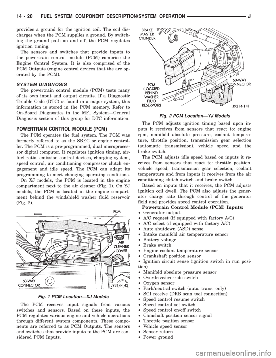
On XJ models, the PCM is located in the engine
compartment next to the air cleaner (Fig. 1). On YJ
models, the PCM is located in the engine compart-
ment behind the windshield washer fluid reservoir
(Fig. 2).
The PCM receives input signals from various
switches and sensors. Based on these inputs, the
PCM regulates various engine and vehicle operations
through different system components. These compo-
nents are referred to as PCM Outputs. The sensors
and switches that provide inputs to the PCM are con-
sidered PCM Inputs.The PCM adjusts ignition timing based upon in-
puts it receives from sensors that react to: engine
rpm, manifold absolute pressure, coolant tempera-
ture, throttle position, transmission gear selection
(automatic transmission), vehicle speed and the
brake switch.
The PCM adjusts idle speed based on inputs it re-
ceives from sensors that react to: throttle position,
vehicle speed, transmission gear selection, coolant
temperature and from inputs it receives from the air
conditioning clutch switch and brake switch.
Based on inputs that it receives, the PCM adjusts
ignition coil dwell. The PCM also adjusts the gener-
ator charge rate through control of the generator
field and provides speed control operation.
Powertrain Control Module (PCM) Inputs:
²Generator output
²A/C request (if equipped with factory A/C)
²A/C select (if equipped with factory A/C)
²Auto shutdown (ASD) sense
²Intake manifold air temperature sensor
²Battery voltage
²Brake switch
²Engine coolant temperature sensor
²Crankshaft position sensor
²Ignition circuit sense (ignition switch in run posi-
tion)
²Manifold absolute pressure sensor
²Overdrive/override switch
²Oxygen sensor
²Park/neutral switch (auto. trans. only)
²SCI receive (DRB scan tool connection)
²Speed control resume switch
²Speed control set switch
²Speed control on/off switch
²Camshaft position sensor signal
²Throttle position sensor
²Vehicle speed sensor
²Sensor return
²Power ground
Fig. 1 PCM LocationÐXJ Models
Fig. 2 PCM LocationÐYJ Models
14 - 20 FUEL SYSTEM COMPONENT DESCRIPTION/SYSTEM OPERATIONJ
Page 1429 of 2158
DATA LINK CONNECTORÐPCM OUTPUT
Refer to the previous paragraphs on Data Link
ConnectorÐPCM Input for information.
EMR LAMPÐPCM OUTPUT
The EMR (SRI) lamp is not used for the 1995
model year.
FUEL PUMP RELAYÐPCM OUTPUT
The PCM energizes the fuel pump and the oxygen
sensor (O2S) heating element through the fuel pump
relay. Battery voltage is applied to the relay from the
ignition switch. The relay is energized when a
ground is provided by the PCM. Refer to Automatic
Shutdown Relay for additional information.
FUEL INJECTORSÐPCM OUTPUT
Six individual fuel injectors are used with the 4.0L
6-cylinder engine. Four individual fuel injectors are
used with the 2.5L 4-cylinder engine. The injectors
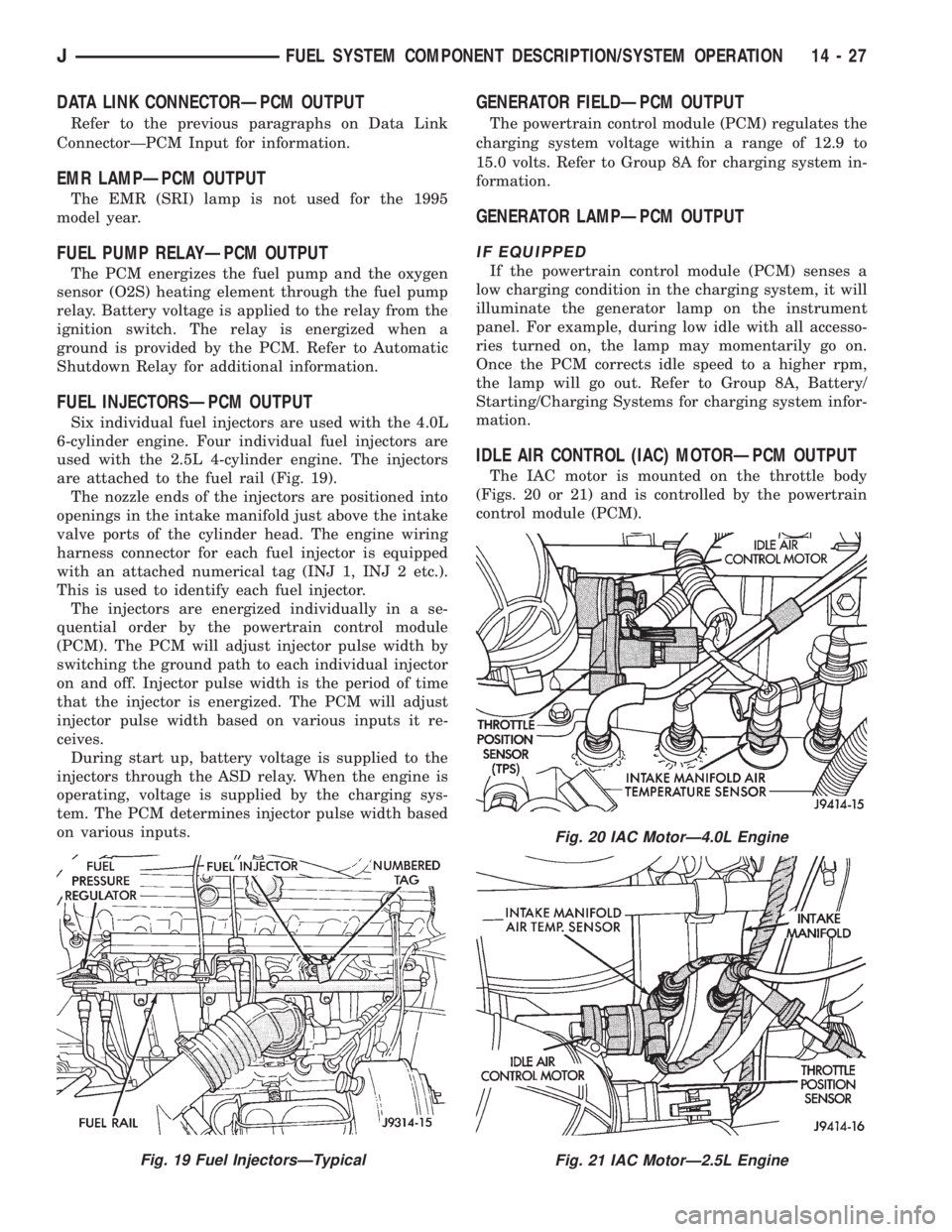
are attached to the fuel rail (Fig. 19).
The nozzle ends of the injectors are positioned into
openings in the intake manifold just above the intake
valve ports of the cylinder head. The engine wiring
harness connector for each fuel injector is equipped
with an attached numerical tag (INJ 1, INJ 2 etc.).
This is used to identify each fuel injector.
The injectors are energized individually in a se-
quential order by the powertrain control module
(PCM). The PCM will adjust injector pulse width by
switching the ground path to each individual injector
on and off. Injector pulse width is the period of time
that the injector is energized. The PCM will adjust
injector pulse width based on various inputs it re-
ceives.
During start up, battery voltage is supplied to the
injectors through the ASD relay. When the engine is
operating, voltage is supplied by the charging sys-
tem. The PCM determines injector pulse width based
on various inputs.
GENERATOR FIELDÐPCM OUTPUT
The powertrain control module (PCM) regulates the
charging system voltage within a range of 12.9 to
15.0 volts. Refer to Group 8A for charging system in-
formation.
GENERATOR LAMPÐPCM OUTPUT
IF EQUIPPED
If the powertrain control module (PCM) senses a
low charging condition in the charging system, it will
illuminate the generator lamp on the instrument
panel. For example, during low idle with all accesso-
ries turned on, the lamp may momentarily go on.
Once the PCM corrects idle speed to a higher rpm,
the lamp will go out. Refer to Group 8A, Battery/
Starting/Charging Systems for charging system infor-
mation.
IDLE AIR CONTROL (IAC) MOTORÐPCM OUTPUT
The IAC motor is mounted on the throttle body
(Figs. 20 or 21) and is controlled by the powertrain
control module (PCM).
Fig. 19 Fuel InjectorsÐTypical
Fig. 20 IAC MotorÐ4.0L Engine
Fig. 21 IAC MotorÐ2.5L Engine
JFUEL SYSTEM COMPONENT DESCRIPTION/SYSTEM OPERATION 14 - 27
Page 1453 of 2158
(8) Disconnect jumper wires from relay and 12 Volt
power source.
If continuity or resistance tests did not pass, re-
place relay. If tests passed, refer to Group 8W, Wiring
Diagrams for additional circuit information. Also re-
fer to the appropriate Powertrain Diagnostic Proce-
dures manual for operation of the DRB scan tool.
STARTER MOTOR RELAY TEST
Refer to Group 8A, Battery/Starting/Charging/Sys-
tem Diagnostics, for starter motor relay testing.
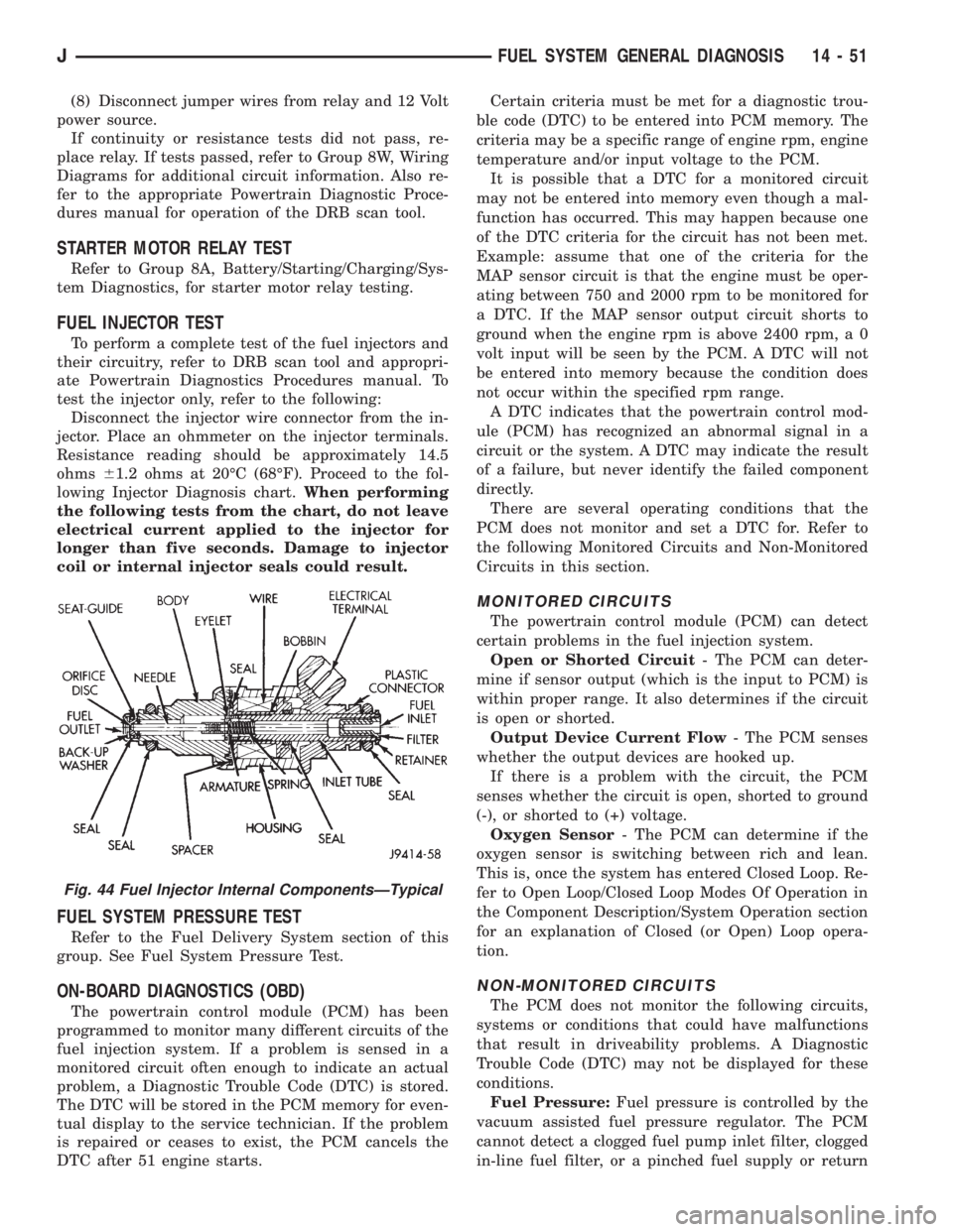
FUEL INJECTOR TEST
To perform a complete test of the fuel injectors and
their circuitry, refer to DRB scan tool and appropri-
ate Powertrain Diagnostics Procedures manual. To
test the injector only, refer to the following:
Disconnect the injector wire connector from the in-
jector. Place an ohmmeter on the injector terminals.
Resistance reading should be approximately 14.5
ohms61.2 ohms at 20ÉC (68ÉF). Proceed to the fol-
lowing Injector Diagnosis chart.When performing
the following tests from the chart, do not leave
electrical current applied to the injector for
longer than five seconds. Damage to injector
coil or internal injector seals could result.
FUEL SYSTEM PRESSURE TEST
Refer to the Fuel Delivery System section of this
group. See Fuel System Pressure Test.
ON-BOARD DIAGNOSTICS (OBD)
The powertrain control module (PCM) has been
programmed to monitor many different circuits of the
fuel injection system. If a problem is sensed in a
monitored circuit often enough to indicate an actual
problem, a Diagnostic Trouble Code (DTC) is stored.
The DTC will be stored in the PCM memory for even-
tual display to the service technician. If the problem
is repaired or ceases to exist, the PCM cancels the
DTC after 51 engine starts.Certain criteria must be met for a diagnostic trou-
ble code (DTC) to be entered into PCM memory. The
criteria may be a specific range of engine rpm, engine
temperature and/or input voltage to the PCM.
It is possible that a DTC for a monitored circuit
may not be entered into memory even though a mal-
function has occurred. This may happen because one
of the DTC criteria for the circuit has not been met.
Example: assume that one of the criteria for the
MAP sensor circuit is that the engine must be oper-
ating between 750 and 2000 rpm to be monitored for
a DTC. If the MAP sensor output circuit shorts to
ground when the engine rpm is above 2400 rpm, a 0
volt input will be seen by the PCM. A DTC will not
be entered into memory because the condition does
not occur within the specified rpm range.
A DTC indicates that the powertrain control mod-
ule (PCM) has recognized an abnormal signal in a
circuit or the system. A DTC may indicate the result
of a failure, but never identify the failed component
directly.
There are several operating conditions that the
PCM does not monitor and set a DTC for. Refer to
the following Monitored Circuits and Non-Monitored
Circuits in this section.
MONITORED CIRCUITS
The powertrain control module (PCM) can detect
certain problems in the fuel injection system.
Open or Shorted Circuit- The PCM can deter-
mine if sensor output (which is the input to PCM) is
within proper range. It also determines if the circuit
is open or shorted.
Output Device Current Flow- The PCM senses
whether the output devices are hooked up.
If there is a problem with the circuit, the PCM
senses whether the circuit is open, shorted to ground
(-), or shorted to (+) voltage.
Oxygen Sensor- The PCM can determine if the
oxygen sensor is switching between rich and lean.
This is, once the system has entered Closed Loop. Re-
fer to Open Loop/Closed Loop Modes Of Operation in
the Component Description/System Operation section
for an explanation of Closed (or Open) Loop opera-
tion.
NON-MONITORED CIRCUITS
The PCM does not monitor the following circuits,
systems or conditions that could have malfunctions
that result in driveability problems. A Diagnostic
Trouble Code (DTC) may not be displayed for these
conditions.
Fuel Pressure:Fuel pressure is controlled by the
vacuum assisted fuel pressure regulator. The PCM
cannot detect a clogged fuel pump inlet filter, clogged
in-line fuel filter, or a pinched fuel supply or return
Fig. 44 Fuel Injector Internal ComponentsÐTypical
JFUEL SYSTEM GENERAL DIAGNOSIS 14 - 51
Page 1459 of 2158
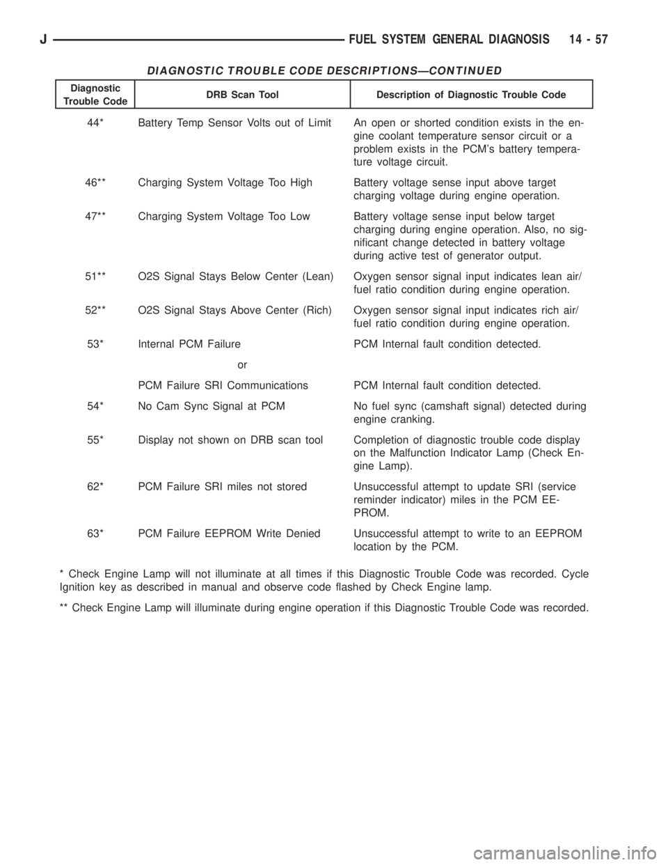
DIAGNOSTIC TROUBLE CODE DESCRIPTIONSÐCONTINUED
Diagnostic
Trouble CodeDRB Scan Tool Description of Diagnostic Trouble Code
44* Battery Temp Sensor Volts out of Limit An open or shorted condition exists in the en-
gine coolant temperature sensor circuit or a
problem exists in the PCM's battery tempera-
ture voltage circuit.
46** Charging System Voltage Too High Battery voltage sense input above target
charging voltage during engine operation.
47** Charging System Voltage Too Low Battery voltage sense input below target
charging during engine operation. Also, no sig-
nificant change detected in battery voltage
during active test of generator output.
51** O2S Signal Stays Below Center (Lean) Oxygen sensor signal input indicates lean air/
fuel ratio condition during engine operation.
52** O2S Signal Stays Above Center (Rich) Oxygen sensor signal input indicates rich air/
fuel ratio condition during engine operation.
53* Internal PCM Failure PCM Internal fault condition detected.
or
PCM Failure SRI Communications PCM Internal fault condition detected.
54* No Cam Sync Signal at PCM No fuel sync (camshaft signal) detected during
engine cranking.
55* Display not shown on DRB scan tool Completion of diagnostic trouble code display
on the Malfunction Indicator Lamp (Check En-
gine Lamp).
62* PCM Failure SRI miles not stored Unsuccessful attempt to update SRI (service
reminder indicator) miles in the PCM EE-
PROM.
63* PCM Failure EEPROM Write Denied Unsuccessful attempt to write to an EEPROM
location by the PCM.
* Check Engine Lamp will not illuminate at all times if this Diagnostic Trouble Code was recorded. Cycle
Ignition key as described in manual and observe code flashed by Check Engine lamp.
** Check Engine Lamp will illuminate during engine operation if this Diagnostic Trouble Code was recorded.
JFUEL SYSTEM GENERAL DIAGNOSIS 14 - 57