1995 JEEP XJ engine
[x] Cancel search: enginePage 1677 of 2158
30RH/32RH TRANSMISSION REMOVAL AND INSTALLATION
INDEX
page page
ConverterÐPump SealÐDrive Plate Service.... 116
Transmission and Converter Installation........ 117Transmission and Converter Removal......... 115
TRANSMISSION AND CONVERTER REMOVAL
(1) Remove fan shroud attaching bolts.
(2) Disconnect transmission fill tube at upper
bracket.
(3) Raise vehicle.
(4) Remove inspection cover from converter hous-
ing and remove skid plate for access, if necessary.
(5) Remove transmission fill tube and fill tube O-
ring.
(6) Remove starter motor.
(7) Mark propeller shafts and axle yokes for align-
ment reference.
(8) Disconnect propeller shafts at yokes. Secure
shafts to frame rails with wire.
(9) Disconnect exhaust pipes at exhaust manifolds,
if necessary.
(10) Drain transfer case lubricant, if transfer case
will also be serviced.
(11) Disconnect vehicle speed sensor wires.
(12) Disconnect transfer case shift linkage.
(13) Disconnect gearshift cable/linkage and throttle
valve cable at transmission levers.
(14) Disconnect transfer case vent hose. Then dis-
connect indicator switch wires on XJ, or vacuum
switch harness on YJ.
(15) Remove wire harness from clips on transfer
case.
(16) Remove transfer case attaching nuts and re-
move transfer case. Use transmission jack or helper
to support and remove transfer case.
(17) Disconnect park/neutral position switch wires.
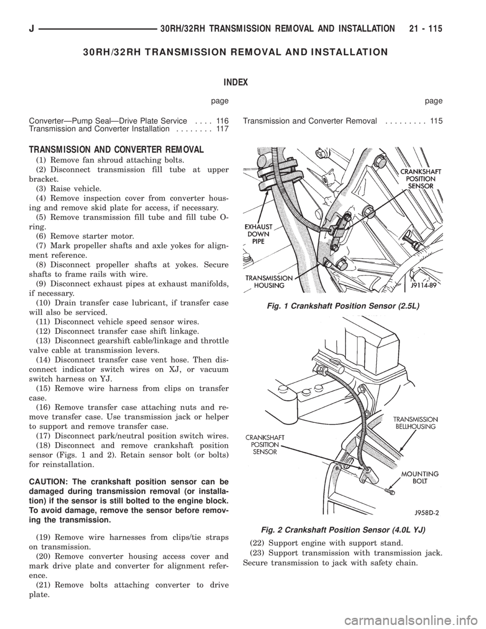
(18) Disconnect and remove crankshaft position
sensor (Figs. 1 and 2). Retain sensor bolt (or bolts)
for reinstallation.
CAUTION: The crankshaft position sensor can be
damaged during transmission removal (or installa-
tion) if the sensor is still bolted to the engine block.
To avoid damage, remove the sensor before remov-
ing the transmission.
(19) Remove wire harnesses from clips/tie straps
on transmission.
(20) Remove converter housing access cover and
mark drive plate and converter for alignment refer-
ence.
(21) Remove bolts attaching converter to drive
plate.(22) Support engine with support stand.
(23) Support transmission with transmission jack.
Secure transmission to jack with safety chain.
Fig. 1 Crankshaft Position Sensor (2.5L)
Fig. 2 Crankshaft Position Sensor (4.0L YJ)
J30RH/32RH TRANSMISSION REMOVAL AND INSTALLATION 21 - 115
Page 1678 of 2158
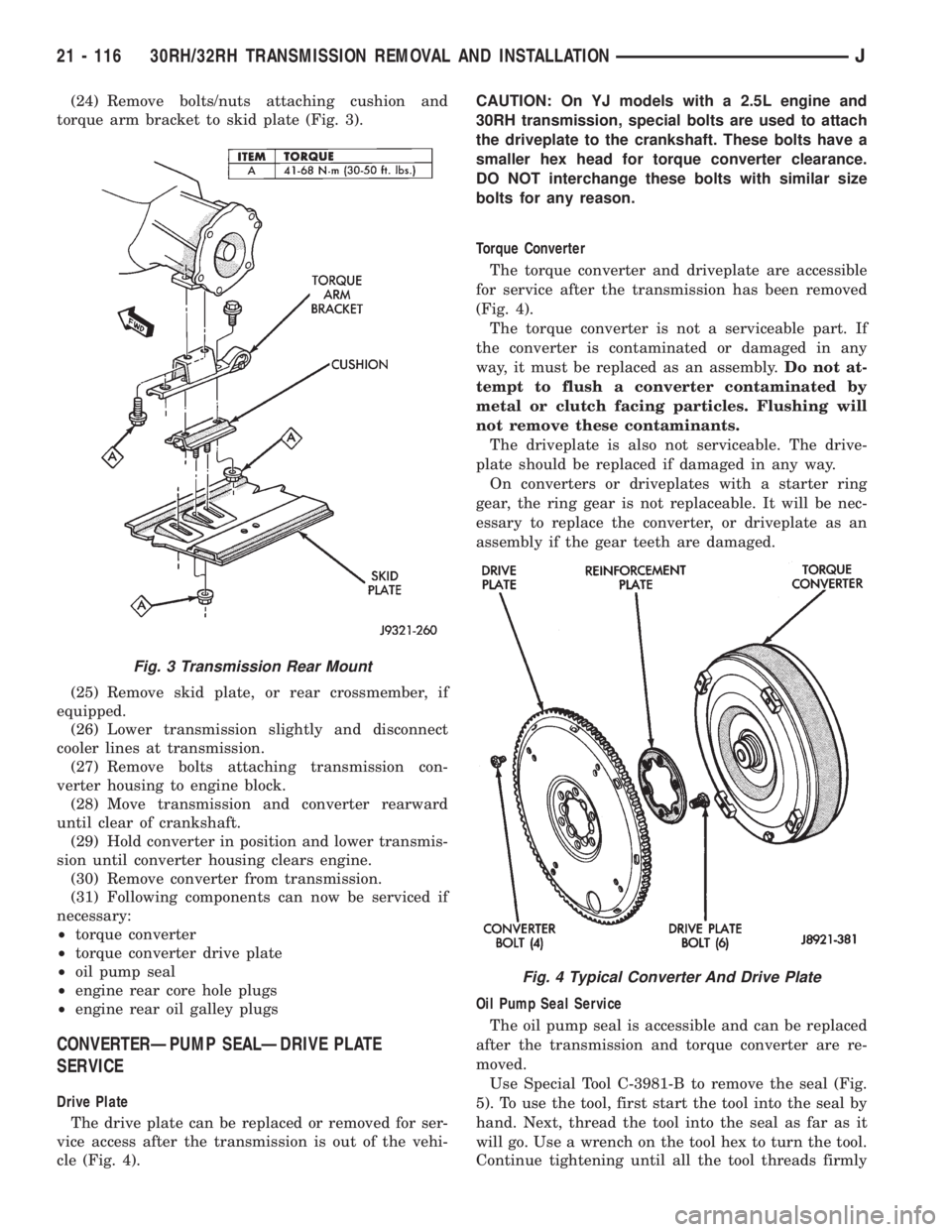
(24) Remove bolts/nuts attaching cushion and
torque arm bracket to skid plate (Fig. 3).
(25) Remove skid plate, or rear crossmember, if
equipped.
(26) Lower transmission slightly and disconnect
cooler lines at transmission.
(27) Remove bolts attaching transmission con-
verter housing to engine block.
(28) Move transmission and converter rearward
until clear of crankshaft.
(29) Hold converter in position and lower transmis-
sion until converter housing clears engine.
(30) Remove converter from transmission.
(31) Following components can now be serviced if
necessary:
²torque converter
²torque converter drive plate
²oil pump seal
²engine rear core hole plugs
²engine rear oil galley plugs
CONVERTERÐPUMP SEALÐDRIVE PLATE
SERVICE
Drive Plate
The drive plate can be replaced or removed for ser-
vice access after the transmission is out of the vehi-
cle (Fig. 4).CAUTION: On YJ models with a 2.5L engine and
30RH transmission, special bolts are used to attach
the driveplate to the crankshaft. These bolts have a
smaller hex head for torque converter clearance.
DO NOT interchange these bolts with similar size
bolts for any reason.
Torque Converter
The torque converter and driveplate are accessible
for service after the transmission has been removed
(Fig. 4).
The torque converter is not a serviceable part. If
the converter is contaminated or damaged in any
way, it must be replaced as an assembly.Do not at-
tempt to flush a converter contaminated by
metal or clutch facing particles. Flushing will
not remove these contaminants.
The driveplate is also not serviceable. The drive-
plate should be replaced if damaged in any way.
On converters or driveplates with a starter ring
gear, the ring gear is not replaceable. It will be nec-
essary to replace the converter, or driveplate as an
assembly if the gear teeth are damaged.
Oil Pump Seal Service
The oil pump seal is accessible and can be replaced
after the transmission and torque converter are re-
moved.
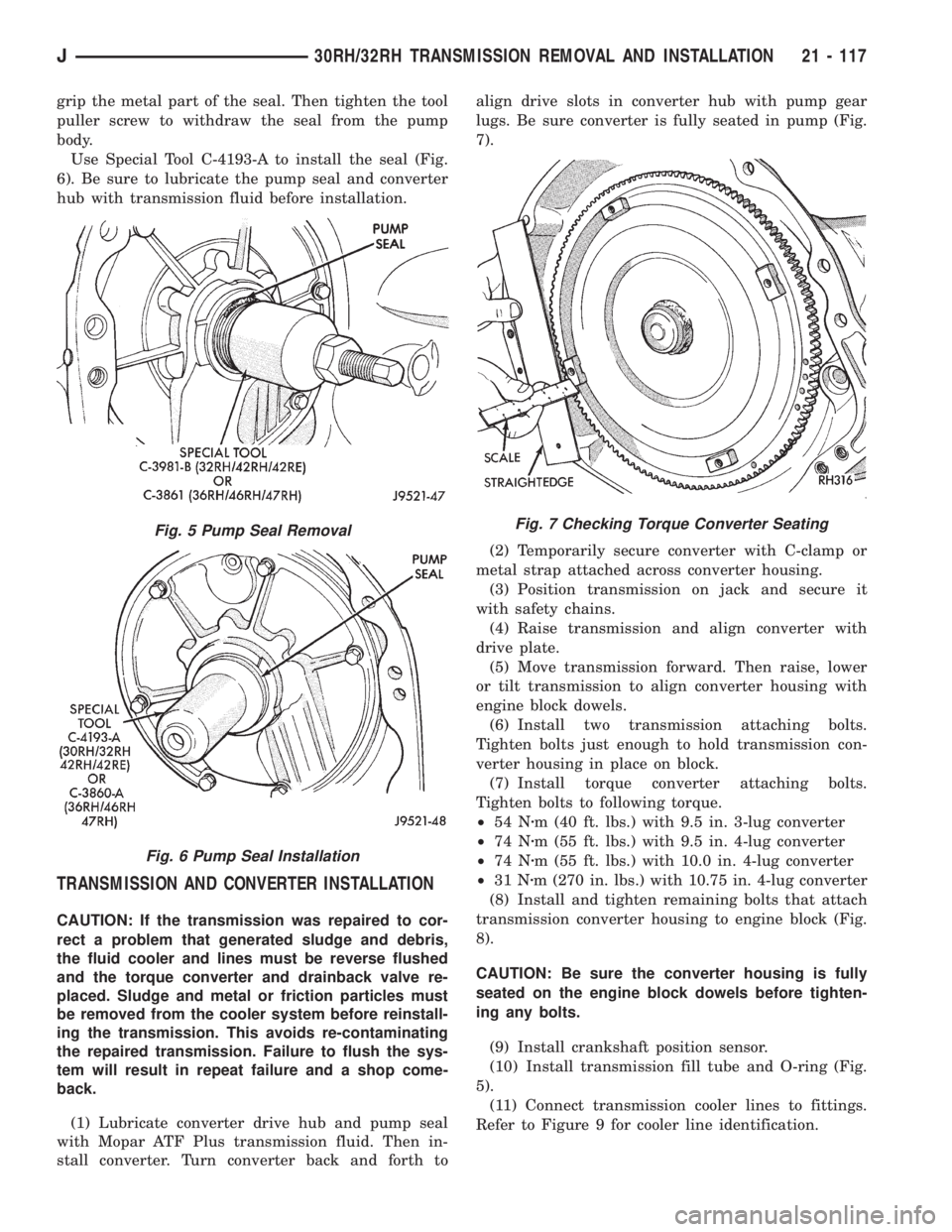
Use Special Tool C-3981-B to remove the seal (Fig.
5). To use the tool, first start the tool into the seal by
hand. Next, thread the tool into the seal as far as it
will go. Use a wrench on the tool hex to turn the tool.
Continue tightening until all the tool threads firmly
Fig. 3 Transmission Rear Mount
Fig. 4 Typical Converter And Drive Plate
21 - 116 30RH/32RH TRANSMISSION REMOVAL AND INSTALLATIONJ
Page 1679 of 2158
grip the metal part of the seal. Then tighten the tool
puller screw to withdraw the seal from the pump
body.
Use Special Tool C-4193-A to install the seal (Fig.
6). Be sure to lubricate the pump seal and converter
hub with transmission fluid before installation.
TRANSMISSION AND CONVERTER INSTALLATION
CAUTION: If the transmission was repaired to cor-
rect a problem that generated sludge and debris,
the fluid cooler and lines must be reverse flushed
and the torque converter and drainback valve re-
placed. Sludge and metal or friction particles must
be removed from the cooler system before reinstall-
ing the transmission. This avoids re-contaminating
the repaired transmission. Failure to flush the sys-
tem will result in repeat failure and a shop come-
back.
(1) Lubricate converter drive hub and pump seal
with Mopar ATF Plus transmission fluid. Then in-
stall converter. Turn converter back and forth toalign drive slots in converter hub with pump gear
lugs. Be sure converter is fully seated in pump (Fig.
7).
(2) Temporarily secure converter with C-clamp or
metal strap attached across converter housing.
(3) Position transmission on jack and secure it
with safety chains.
(4) Raise transmission and align converter with
drive plate.
(5) Move transmission forward. Then raise, lower
or tilt transmission to align converter housing with
engine block dowels.
(6) Install two transmission attaching bolts.
Tighten bolts just enough to hold transmission con-
verter housing in place on block.
(7) Install torque converter attaching bolts.
Tighten bolts to following torque.
²54 Nzm (40 ft. lbs.) with 9.5 in. 3-lug converter
²74 Nzm (55 ft. lbs.) with 9.5 in. 4-lug converter
²74 Nzm (55 ft. lbs.) with 10.0 in. 4-lug converter
²31 Nzm (270 in. lbs.) with 10.75 in. 4-lug converter
(8) Install and tighten remaining bolts that attach
transmission converter housing to engine block (Fig.
8).
CAUTION: Be sure the converter housing is fully
seated on the engine block dowels before tighten-
ing any bolts.
(9) Install crankshaft position sensor.
(10) Install transmission fill tube and O-ring (Fig.
5).
(11) Connect transmission cooler lines to fittings.
Refer to Figure 9 for cooler line identification.
Fig. 5 Pump Seal Removal
Fig. 6 Pump Seal Installation
Fig. 7 Checking Torque Converter Seating
J30RH/32RH TRANSMISSION REMOVAL AND INSTALLATION 21 - 117
Page 1727 of 2158
AW-4 AUTOMATIC TRANSMISSION
CONTENTS
page page
AW-4 AUTOMATIC TRANSMISSION........ 165
AW-4 IN-VEHICLE SERVICE.............. 182
AW-4 TRANSMISSION DIAGNOSIS......... 176
AW-4 TRANSMISSION OVERHAUL......... 201AW-4 TRANSMISSION REMOVAL AND
INSTALLATION....................... 198
GENERAL INFORMATION................ 165
GENERAL INFORMATION
INDEX
page page
Components and Operation................. 166
Description............................. 165
First/Second/Third/Reverse Components....... 168
Fourth Gear Overdrive Components.......... 167
Geartrain Operation and Application Charts..... 169Hydraulic System........................ 169
Recommended Fluid and Capacity........... 166
Torque Converter........................ 167
Transmission Identification.................. 166
Transmission Ranges and Shift Lever Positions . . 166
DESCRIPTION
AW-4 Transmission Overhaul
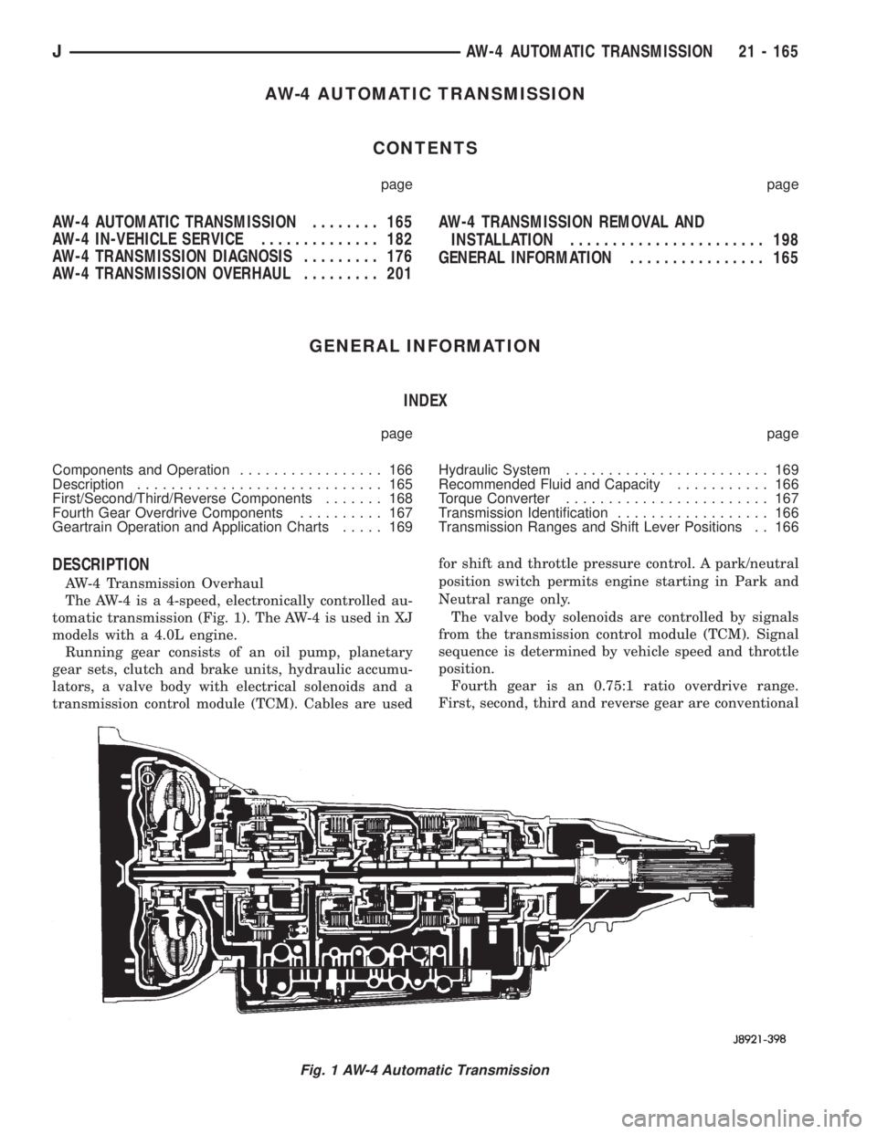
The AW-4 is a 4-speed, electronically controlled au-
tomatic transmission (Fig. 1). The AW-4 is used in XJ
models with a 4.0L engine.
Running gear consists of an oil pump, planetary
gear sets, clutch and brake units, hydraulic accumu-
lators, a valve body with electrical solenoids and a
transmission control module (TCM). Cables are usedfor shift and throttle pressure control. A park/neutral
position switch permits engine starting in Park and
Neutral range only.
The valve body solenoids are controlled by signals
from the transmission control module (TCM). Signal
sequence is determined by vehicle speed and throttle
position.
Fourth gear is an 0.75:1 ratio overdrive range.
First, second, third and reverse gear are conventional
Fig. 1 AW-4 Automatic Transmission
JAW-4 AUTOMATIC TRANSMISSION 21 - 165
Page 1729 of 2158
The transmission speed sensor consists of a rotor
and magnet on the transmission output shaft and a
switch in the extension housing or adapter. The sen-
sor switch is activated each time the rotor and mag-
net complete one revolution. Sensor signals are sent
to the transmission control module.
The park/neutral position switch is mounted on the
valve body manual shaft. The switch signals shift
linkage and manual valve position to the transmis-
sion control module through an interconnecting har-
ness. The switch prevents engine starting in all gears
other than Park or Neutral.
The brake switch is in circuit with the torque con-
verter clutch solenoid. The switch disengages the
converter clutch whenever the brakes are applied.
The switch is mounted on the brake pedal bracket
and signals the transmission control module when
the pedal is pressed or released.
TORQUE CONVERTER
A three element torque converter is used for all ap-
plications. The converter contains an impeller, stator,
and turbine.
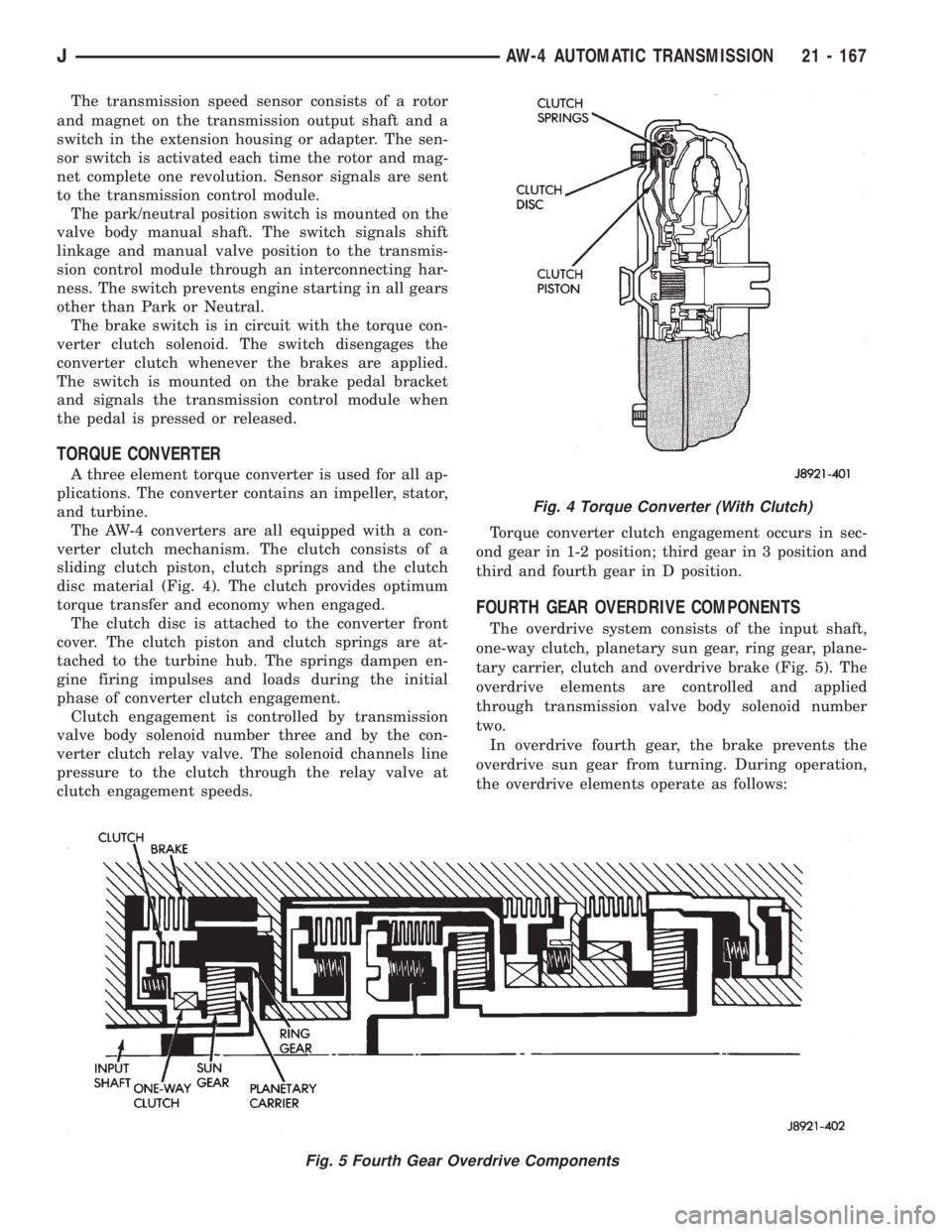
The AW-4 converters are all equipped with a con-
verter clutch mechanism. The clutch consists of a
sliding clutch piston, clutch springs and the clutch
disc material (Fig. 4). The clutch provides optimum
torque transfer and economy when engaged.
The clutch disc is attached to the converter front
cover. The clutch piston and clutch springs are at-
tached to the turbine hub. The springs dampen en-
gine firing impulses and loads during the initial
phase of converter clutch engagement.
Clutch engagement is controlled by transmission
valve body solenoid number three and by the con-
verter clutch relay valve. The solenoid channels line
pressure to the clutch through the relay valve at
clutch engagement speeds.Torque converter clutch engagement occurs in sec-
ond gear in 1-2 position; third gear in 3 position and
third and fourth gear in D position.
FOURTH GEAR OVERDRIVE COMPONENTS
The overdrive system consists of the input shaft,
one-way clutch, planetary sun gear, ring gear, plane-
tary carrier, clutch and overdrive brake (Fig. 5). The
overdrive elements are controlled and applied
through transmission valve body solenoid number
two.
In overdrive fourth gear, the brake prevents the
overdrive sun gear from turning. During operation,
the overdrive elements operate as follows:
Fig. 4 Torque Converter (With Clutch)
Fig. 5 Fourth Gear Overdrive Components
JAW-4 AUTOMATIC TRANSMISSION 21 - 167
Page 1732 of 2158
The manual valve, 1-2 shift valve, primary regula-
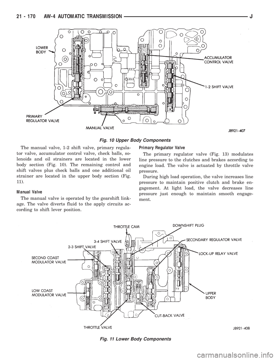
tor valve, accumulator control valve, check balls, so-
lenoids and oil strainers are located in the lower
body section (Fig. 10). The remaining control and
shift valves plus check balls and one additional oil
strainer are located in the upper body section (Fig.
11).
Manual Valve
The manual valve is operated by the gearshift link-
age. The valve diverts fluid to the apply circuits ac-
cording to shift lever position.Primary Regulator Valve
The primary regulator valve (Fig. 13) modulates
line pressure to the clutches and brakes according to
engine load. The valve is actuated by throttle valve
pressure.
During high load operation, the valve increases line
pressure to maintain positive clutch and brake en-
gagement. At light load, the valve decreases line
pressure just enough to maintain smooth engage-
ment.
Fig. 10 Upper Body Components
Fig. 11 Lower Body Components
21 - 170 AW-4 AUTOMATIC TRANSMISSIONJ
Page 1733 of 2158
Throttle Valve and Downshift Plug
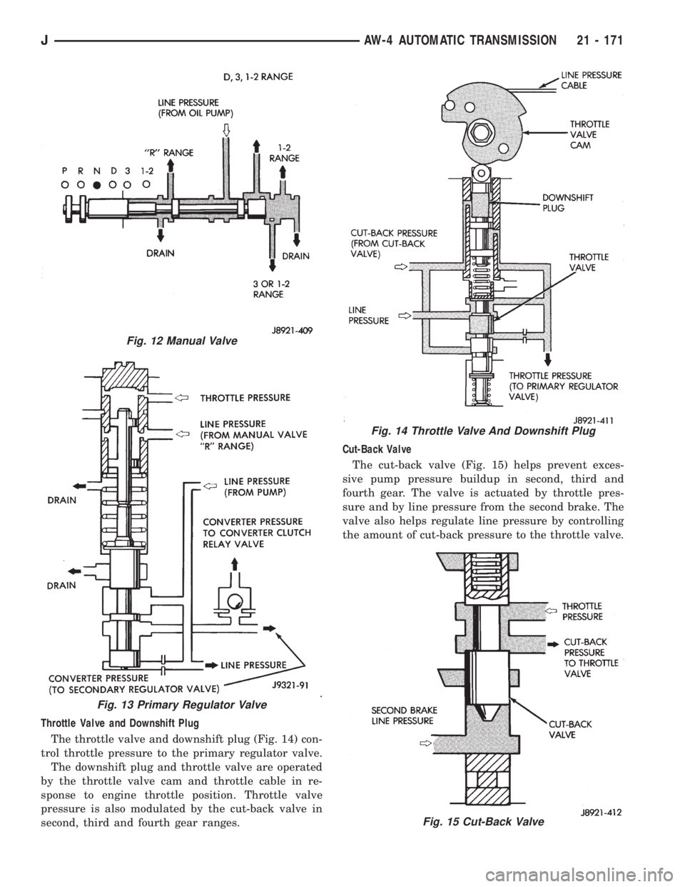
The throttle valve and downshift plug (Fig. 14) con-
trol throttle pressure to the primary regulator valve.
The downshift plug and throttle valve are operated
by the throttle valve cam and throttle cable in re-
sponse to engine throttle position. Throttle valve
pressure is also modulated by the cut-back valve in
second, third and fourth gear ranges.Cut-Back Valve
The cut-back valve (Fig. 15) helps prevent exces-
sive pump pressure buildup in second, third and
fourth gear. The valve is actuated by throttle pres-
sure and by line pressure from the second brake. The
valve also helps regulate line pressure by controlling
the amount of cut-back pressure to the throttle valve.
Fig. 12 Manual Valve
Fig. 13 Primary Regulator Valve
Fig. 14 Throttle Valve And Downshift Plug
Fig. 15 Cut-Back Valve
JAW-4 AUTOMATIC TRANSMISSION 21 - 171
Page 1739 of 2158
(2) Verify transmission throttle cable operation.
Repair or replace cable if necessary.
(3) Check engine throttle operation. Operate accel-
erator pedal and observe injector throttle plate move-
ment. Adjust linkage if throttle plate does not reach
wide open position.
(4) Check transmission fluid level when fluid is at
normal operating temperature. Start engine. Shift
transmission through all gear ranges then back to
Neutral. Correct level is to Full or Add mark on dip-
stick with engine at curb idle speed.
(5) Check and adjust park/neutral position switch
if necessary.
(6) Check throttle position sensor adjustment and
operation. Adjust the sensor if necessary.
MANUAL SHIFTING TEST
(1) This test determines if problem is related to
mechanical or electrical component.
(2) Stop engine and disconnect transmission con-
trol module or module fuse.
(3) Road test vehicle. Shift transmission into each
gear range. Transmission should operate as follows:
²lock in Park
²back up in Reverse
²not move in Neutral
²provide first gear only with shift lever in 1-2 posi-
tion
²operate in third gear only with shift lever in 3 po-
sition
²operate in overdrive fourth gear in D position
(4) If transmission operates as described, proceed
to next step. However, if forward gear ranges were
difficult to distinguish (all feel the same), or vehicle
would not back up, refer to diagnosis charts. Do not
perform stall or time lag tests.
CAUTION: Do not overspeed the engine during the
next test step. Ease off the throttle and allow the
vehicle to slow before downshifting.
(5) Continue road test. Manually downshift trans-
mission from D to 3, and from 3 to 1-2 position. Then
manually upshift transmission through forward
ranges again.
(6) If transmission operation is OK, perform stall,
time lag and pressure tests. If transmission shifting
problem is encountered, refer to diagnosis charts.
(7) If a problem still exists, continue testing with
DRB scan tool.
HYDRAULIC PRESSURE TEST
PRESSURE TEST PROCEDURE
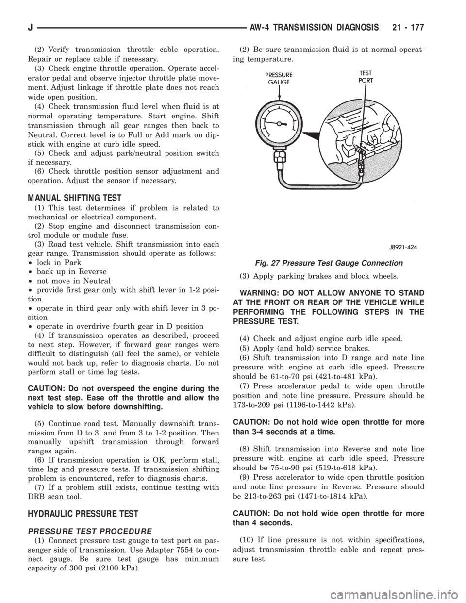
(1) Connect pressure test gauge to test port on pas-
senger side of transmission. Use Adapter 7554 to con-
nect gauge. Be sure test gauge has minimum
capacity of 300 psi (2100 kPa).(2) Be sure transmission fluid is at normal operat-
ing temperature.
(3) Apply parking brakes and block wheels.
WARNING: DO NOT ALLOW ANYONE TO STAND
AT THE FRONT OR REAR OF THE VEHICLE WHILE
PERFORMING THE FOLLOWING STEPS IN THE
PRESSURE TEST.
(4) Check and adjust engine curb idle speed.
(5) Apply (and hold) service brakes.
(6) Shift transmission into D range and note line
pressure with engine at curb idle speed. Pressure
should be 61-to-70 psi (421-to-481 kPa).
(7) Press accelerator pedal to wide open throttle
position and note line pressure. Pressure should be
173-to-209 psi (1196-to-1442 kPa).
CAUTION: Do not hold wide open throttle for more
than 3-4 seconds at a time.
(8) Shift transmission into Reverse and note line
pressure with engine at curb idle speed. Pressure
should be 75-to-90 psi (519-to-618 kPa).
(9) Press accelerator to wide open throttle position
and note line pressure in Reverse. Pressure should
be 213-to-263 psi (1471-to-1814 kPa).
CAUTION: Do not hold wide open throttle for more
than 4 seconds.
(10) If line pressure is not within specifications,
adjust transmission throttle cable and repeat pres-
sure test.
Fig. 27 Pressure Test Gauge Connection
JAW-4 TRANSMISSION DIAGNOSIS 21 - 177