1995 JEEP XJ weight
[x] Cancel search: weightPage 482 of 2158
SERVICE PROCEDURES
INDEX
page page
Back-Up/Rear Turn Signal/Tail Lamp Bulb
ReplacementÐYJ....................... 28
Center High Mounted Stop Lamp (CHMSL)ÐYJ . . 28
Daytime Running Lights (Canada Only)ÐYJ..... 30
Drl Module ReplacementÐYJ................ 30
Fog Lamp ReplacementÐYJ................. 25
Fog Lamp Switch ReplacementÐYJ........... 26
Fog LampsÐYJ.......................... 23
Front Park/Turn Signal Lamp Bulb ReplacementÐ
YJ ................................... 25
Headlamp Alignment PreparationÐYJ.......... 22Headlamp AlignmentÐYJ................... 22
Headlamp Bulb ReplacementÐYJ............. 23
Headlamp Dimmer Switch ReplacementÐYJ..... 26
Headlamp SwitchÐYJ...................... 26
Headlamp/Fog Lamp Adjustment Using Alignment
ScreenÐYJ............................ 23
Side Marker Lamp Bulb ReplacementÐYJ....... 25
Underhood Lamp Bulb ReplacementÐYJ....... 29
Underhood Lamp ReplacementÐYJ........... 29
Underhood Lamp Service InformationÐYJ....... 28
HEADLAMP ALIGNMENTÐYJ
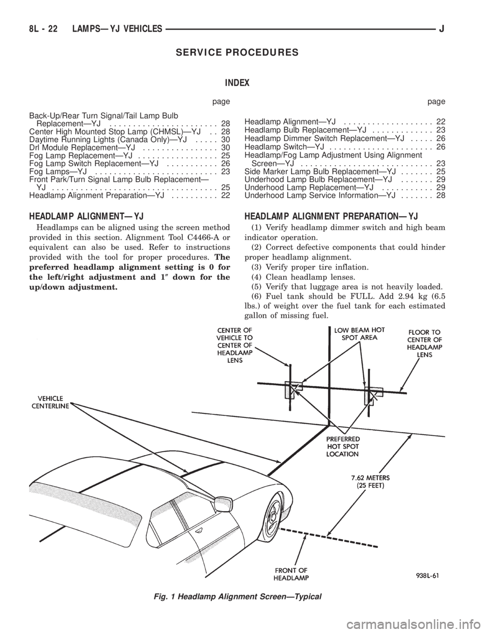
Headlamps can be aligned using the screen method
provided in this section. Alignment Tool C4466-A or
equivalent can also be used. Refer to instructions
provided with the tool for proper procedures.The
preferred headlamp alignment setting is 0 for
the left/right adjustment and 1(down for the
up/down adjustment.
HEADLAMP ALIGNMENT PREPARATIONÐYJ
(1) Verify headlamp dimmer switch and high beam
indicator operation.
(2) Correct defective components that could hinder
proper headlamp alignment.
(3) Verify proper tire inflation.
(4) Clean headlamp lenses.
(5) Verify that luggage area is not heavily loaded.
(6) Fuel tank should be FULL. Add 2.94 kg (6.5
lbs.) of weight over the fuel tank for each estimated
gallon of missing fuel.
Fig. 1 Headlamp Alignment ScreenÐTypical
8L - 22 LAMPSÐYJ VEHICLESJ
Page 1282 of 2158
CAUTION: DO NOT use engine or transmission oil,
mineral spirits or kerosene.
(3) Honing should be done by moving the hone up
and down fast enough to get a crosshatch pattern.
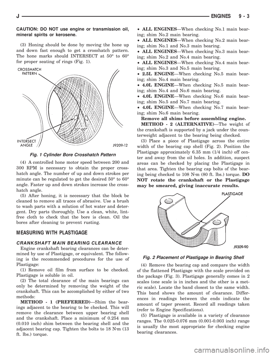
The hone marks should INTERSECT at 50É to 60É
for proper seating of rings (Fig. 1).
(4) A controlled hone motor speed between 200 and
300 RPM is necessary to obtain the proper cross-
hatch angle. The number of up and down strokes per
minute can be regulated to get the desired 50É to 60É
angle. Faster up and down strokes increase the cross-
hatch angle.
(5) After honing, it is necessary that the block be
cleaned to remove all traces of abrasive. Use a brush
to wash parts with a solution of hot water and deter-
gent. Dry parts thoroughly. Use a clean, white, lint-
free cloth to check that the bore is clean. Oil the
bores after cleaning to prevent rusting.
MEASURING WITH PLASTIGAGE
CRANKSHAFT MAIN BEARING CLEARANCE
Engine crankshaft bearing clearances can be deter-
mined by use of Plastigage, or equivalent. The follow-
ing is the recommended procedures for the use of
Plastigage:
(1) Remove oil film from surface to be checked.
Plastigage is soluble in oil.
(2) The total clearance of the main bearings can
only be determined by removing the weight of the
crankshaft. This can be accomplished by either of two
methods:
METHOD - 1 (PREFERRED)ÐShim the bear-
ings adjacent to the bearing to be checked. This will
remove the clearance between upper bearing shell
and the crankshaft. Place a minimum of 0.254 mm
(0.010 inch) shim between the bearing shell and the
adjacent bearing cap. Tighten the bolts to 18 Nzm (13
ft. lbs.) torque.²ALL ENGINESÐWhen checking No.1 main bear-
ing; shim No.2 main bearing.
²ALL ENGINESÐWhen checking No.2 main bear-
ing; shim No.1 and No.3 main bearing.
²ALL ENGINESÐWhen checking No.3 main bear-
ing; shim No.2 and No.4 main bearing.
²ALL ENGINESÐWhen checking No.4 main bear-
ing; shim No.3 and No.5 main bearing.
²2.5L ENGINEÐWhen checking No.5 main bear-
ing; shim No.4 main bearing.
²4.0L ENGINEÐWhen checking No.5 main bear-
ing; shim No.4 and No.6 main bearing.
²4.0L ENGINEÐWhen checking No.6 main bear-
ing; shim No.5 and No.7 main bearing.
²4.0L ENGINEÐWhen checking No.7 main bear-
ing; shim No.6 main bearing.
Remove all shims before assembling engine.
METHOD - 2 (ALTERNATIVE)ÐThe weight of
the crankshaft is supported by a jack under the coun-
terweight adjacent to the bearing being checked.
(3) Place a piece of Plastigage across the entire
width of the bearing cap shell (Fig. 2). Position the
Plastigage approximately 6.35 mm (1/4 inch) off cen-
ter and away from the oil holes. In addition, suspect
areas can be checked by placing the Plastigage in
that area. Tighten the bearing cap bolts of the bear-
ing being checked to 108 Nzm (80 ft. lbs.) torque.DO
NOT rotate the crankshaft or the Plastigage
may be smeared, giving inaccurate results.
(4) Remove the bearing cap and compare the width
of the flattened Plastigage with the scale provided on
the package (Fig. 3). Plastigage generally comes in 2
scales (one scale is in inches and the other is a met-
ric scale). Locate the band closest to the same width.
This band shows the amount of clearance. Differ-
ences in readings between the ends indicate the
amount of taper present. Record all readings taken
(refer to Engine Specifications).
(5) Plastigage is available in a variety of clearance
ranges. The 0.025-0.076 mm (0.001-0.003 inch) range
is usually the most appropriate for checking engine
bearing clearances.
Fig. 1 Cylinder Bore Crosshatch Pattern
Fig. 2 Placement of Plastigage in Bearing Shell
JENGINES 9 - 3
Page 1292 of 2158
2.5L ENGINE SERVICE PROCEDURES
INDEX
page page
Camshaft............................... 32
Camshaft Pin Replacement.................. 34
Engine AssemblyÐXJ Vehicles............... 18
Engine AssemblyÐYJ Vehicles............... 20
Engine Cylinder Head...................... 25
Engine Cylinder Head Cover................. 22
Engine Damper........................... 17
Engine MountÐRear....................... 16
Engine MountsÐFront..................... 14
General Information....................... 13
Hydraulic Tappets......................... 24OilPan ................................. 36
Rocker Arms and Push Rods................ 23
Timing Case Cover........................ 31
Timing Case Cover Oil Seal Replacement....... 30
Timing Chain and Sprockets................. 31
Valve Component ReplaceÐCylinder Head Not
Removed.............................. 23
Valve Springs and Oil Seals................. 23
Valve Timing............................. 30
Valves and Valve Springs................... 27
Vibration Damper......................... 30
GENERAL INFORMATION
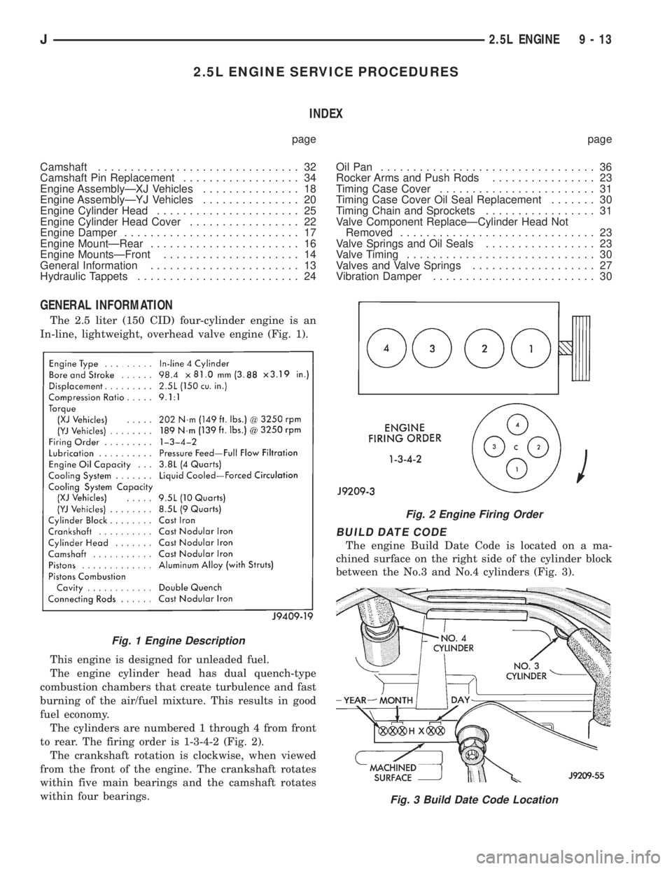
The 2.5 liter (150 CID) four-cylinder engine is an
In-line, lightweight, overhead valve engine (Fig. 1).
This engine is designed for unleaded fuel.
The engine cylinder head has dual quench-type
combustion chambers that create turbulence and fast
burning of the air/fuel mixture. This results in good
fuel economy.
The cylinders are numbered 1 through 4 from front
to rear. The firing order is 1-3-4-2 (Fig. 2).
The crankshaft rotation is clockwise, when viewed
from the front of the engine. The crankshaft rotates
within five main bearings and the camshaft rotates
within four bearings.
BUILD DATE CODE
The engine Build Date Code is located on a ma-
chined surface on the right side of the cylinder block
between the No.3 and No.4 cylinders (Fig. 3).
Fig. 1 Engine Description
Fig. 2 Engine Firing Order
Fig. 3 Build Date Code Location
J2.5L ENGINE 9 - 13
Page 1304 of 2158
LEAK-DOWN TEST
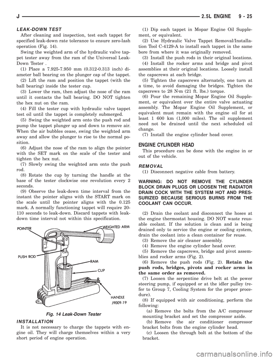
After cleaning and inspection, test each tappet for
specified leak-down rate tolerance to ensure zero-lash
operation (Fig. 14).
Swing the weighted arm of the hydraulic valve tap-
pet tester away from the ram of the Universal Leak-
Down Tester .
(1) Place a 7.925-7.950 mm (0.312-0.313 inch) di-
ameter ball bearing on the plunger cap of the tappet.
(2) Lift the ram and position the tappet (with the
ball bearing) inside the tester cup.
(3) Lower the ram, then adjust the nose of the ram
until it contacts the ball bearing. DO NOT tighten
the hex nut on the ram.
(4) Fill the tester cup with hydraulic valve tappet
test oil until the tappet is completely submerged.
(5) Swing the weighted arm onto the push rod and
pump the tappet plunger up and down to remove air.
When the air bubbles cease, swing the weighted arm
away and allow the plunger to rise to the normal po-
sition.
(6) Adjust the nose of the ram to align the pointer
with the SET mark on the scale of the tester and
tighten the hex nut.
(7) Slowly swing the weighted arm onto the push
rod.
(8) Rotate the cup by turning the handle at the
base of the tester clockwise one revolution every 2
seconds.
(9) Observe the leak-down time interval from the
instant the pointer aligns with the START mark on
the scale until the pointer aligns with the 0.125
mark. A normally functioning tappet will require 20-
110 seconds to leak-down. Discard tappets with leak-
down time interval not within this specification.
INSTALLATION
It is not necessary to charge the tappets with en-
gine oil. They will charge themselves within a very
short period of engine operation.(1) Dip each tappet in Mopar Engine Oil Supple-
ment, or equivalent.
(2) Use Hydraulic Valve Tappet Removal/Installa-
tion Tool C-4129-A to install each tappet in the same
bore from where it was originally removed.
(3) Install the push rods in their original locations.
(4) Install the rocker arms and bridge and pivot
assemblies at their original locations. Loosely install
the capscrews at each bridge.
(5) Tighten the capscrews alternately, one turn at
a time, to avoid damaging the bridges. Tighten the
capscrews to 28 Nzm (21 ft. lbs.) torque.
(6) Pour the remaining Mopar Engine Oil Supple-
ment, or equivalent over the entire valve actuating
assembly. The Mopar Engine Oil Supplement, or
equivalent must remain with the engine oil for at
least 1 600 km (1,000 miles). The oil supplement
need not be drained until the next scheduled oil
change.
(7) Install the engine cylinder head cover.
ENGINE CYLINDER HEAD
This procedure can be done with the engine in or
out of the vehicle.
REMOVAL
(1) Disconnect negative cable from battery.
WARNING: DO NOT REMOVE THE CYLINDER
BLOCK DRAIN PLUGS OR LOOSEN THE RADIATOR
DRAIN COCK WITH THE SYSTEM HOT AND PRES-
SURIZED BECAUSE SERIOUS BURNS FROM THE
COOLANT CAN OCCUR.
(2) Drain the coolant and disconnect the hoses at
the engine thermostat housing. DO NOT waste reus-
able coolant. If the solution is clean and is being
drained only to service the engine or cooling system,
drain the coolant into a clean container for reuse.
(3) Remove the air cleaner assembly.
(4) Remove the engine cylinder head cover.
(5) Remove the capscrews, bridge and pivot assem-
blies and rocker arms (Fig. 2).
(6) Remove the push rods (Fig. 2).Retain the
push rods, bridges, pivots and rocker arms in
the same order as removed.
(7) Loosen the serpentine drive belt at the power
steering pump, if equipped or at the idler pulley (re-
fer to Group 7, Cooling System for the proper proce-
dure).
(8) If equipped with air conditioning, perform the
following:
(a) Remove the bolts from the A/C compressor
mounting bracket and set the compressor aside.
(b) Remove the air conditioner compressor
bracket bolts from the engine cylinder head.
(c) Loosen the through bolt at the bottom of the
bracket.
Fig. 14 Leak-Down Tester
J2.5L ENGINE 9 - 25
Page 1323 of 2158
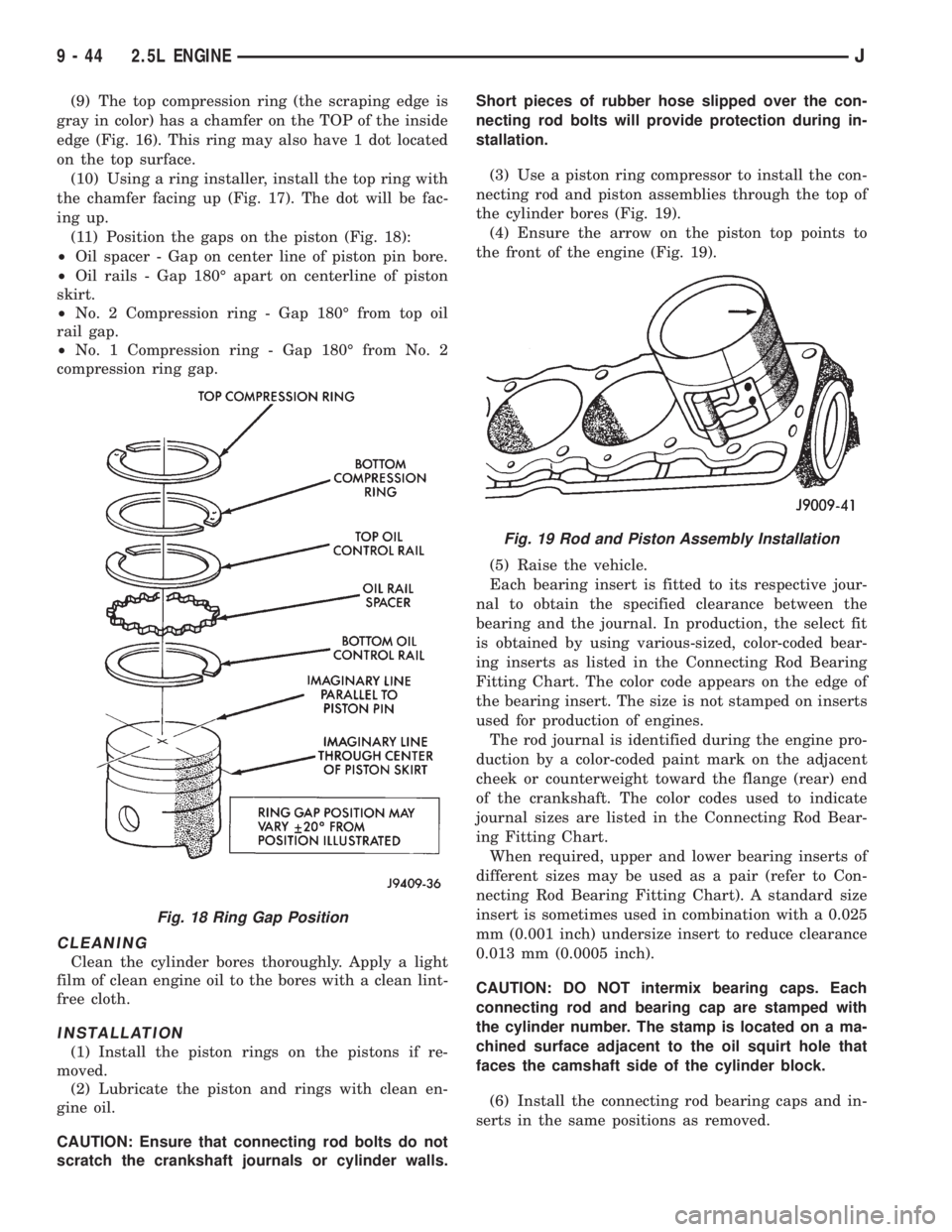
(9) The top compression ring (the scraping edge is
gray in color) has a chamfer on the TOP of the inside
edge (Fig. 16). This ring may also have 1 dot located
on the top surface.
(10) Using a ring installer, install the top ring with
the chamfer facing up (Fig. 17). The dot will be fac-
ing up.
(11) Position the gaps on the piston (Fig. 18):
²Oil spacer - Gap on center line of piston pin bore.
²Oil rails - Gap 180É apart on centerline of piston
skirt.
²No. 2 Compression ring - Gap 180É from top oil
rail gap.
²No. 1 Compression ring - Gap 180É from No. 2
compression ring gap.
CLEANING
Clean the cylinder bores thoroughly. Apply a light
film of clean engine oil to the bores with a clean lint-
free cloth.
INSTALLATION
(1) Install the piston rings on the pistons if re-
moved.
(2) Lubricate the piston and rings with clean en-
gine oil.
CAUTION: Ensure that connecting rod bolts do not
scratch the crankshaft journals or cylinder walls.Short pieces of rubber hose slipped over the con-
necting rod bolts will provide protection during in-
stallation.
(3) Use a piston ring compressor to install the con-
necting rod and piston assemblies through the top of
the cylinder bores (Fig. 19).
(4) Ensure the arrow on the piston top points to
the front of the engine (Fig. 19).
(5) Raise the vehicle.
Each bearing insert is fitted to its respective jour-
nal to obtain the specified clearance between the
bearing and the journal. In production, the select fit
is obtained by using various-sized, color-coded bear-
ing inserts as listed in the Connecting Rod Bearing
Fitting Chart. The color code appears on the edge of
the bearing insert. The size is not stamped on inserts
used for production of engines.
The rod journal is identified during the engine pro-
duction by a color-coded paint mark on the adjacent
cheek or counterweight toward the flange (rear) end
of the crankshaft. The color codes used to indicate
journal sizes are listed in the Connecting Rod Bear-
ing Fitting Chart.
When required, upper and lower bearing inserts of
different sizes may be used as a pair (refer to Con-
necting Rod Bearing Fitting Chart). A standard size
insert is sometimes used in combination with a 0.025
mm (0.001 inch) undersize insert to reduce clearance
0.013 mm (0.0005 inch).
CAUTION: DO NOT intermix bearing caps. Each
connecting rod and bearing cap are stamped with
the cylinder number. The stamp is located on a ma-
chined surface adjacent to the oil squirt hole that
faces the camshaft side of the cylinder block.
(6) Install the connecting rod bearing caps and in-
serts in the same positions as removed.
Fig. 18 Ring Gap Position
Fig. 19 Rod and Piston Assembly Installation
9 - 44 2.5L ENGINEJ
Page 1334 of 2158
4.0L ENGINE SERVICE PROCEDURES
INDEX
page page
Camshaft............................... 74
Camshaft Pin Replacement.................. 75
Engine AssemblyÐXJ Vehicles............... 59
Engine AssemblyÐYJ Vehicles............... 62
Engine Cylinder Head...................... 67
Engine Cylinder Head Cover................. 64
Engine MountÐRear....................... 57
Engine MountsÐFront..................... 56
General Information....................... 55
Hydraulic Tappets......................... 66
OilPan ................................. 77Rocker Arms and Push Rods................ 65
Timing Case Cover........................ 72
Timing Case Cover Oil Seal Replacement....... 73
Timing Chain and Sprockets................. 73
Valve Component ReplaceÐCylinder Head Not
Removed.............................. 65
Valve Stem Seal and Spring Replacement....... 65
Valve Timing............................. 71
Valves and Valve Springs................... 69
Vibration Damper......................... 72
GENERAL INFORMATION
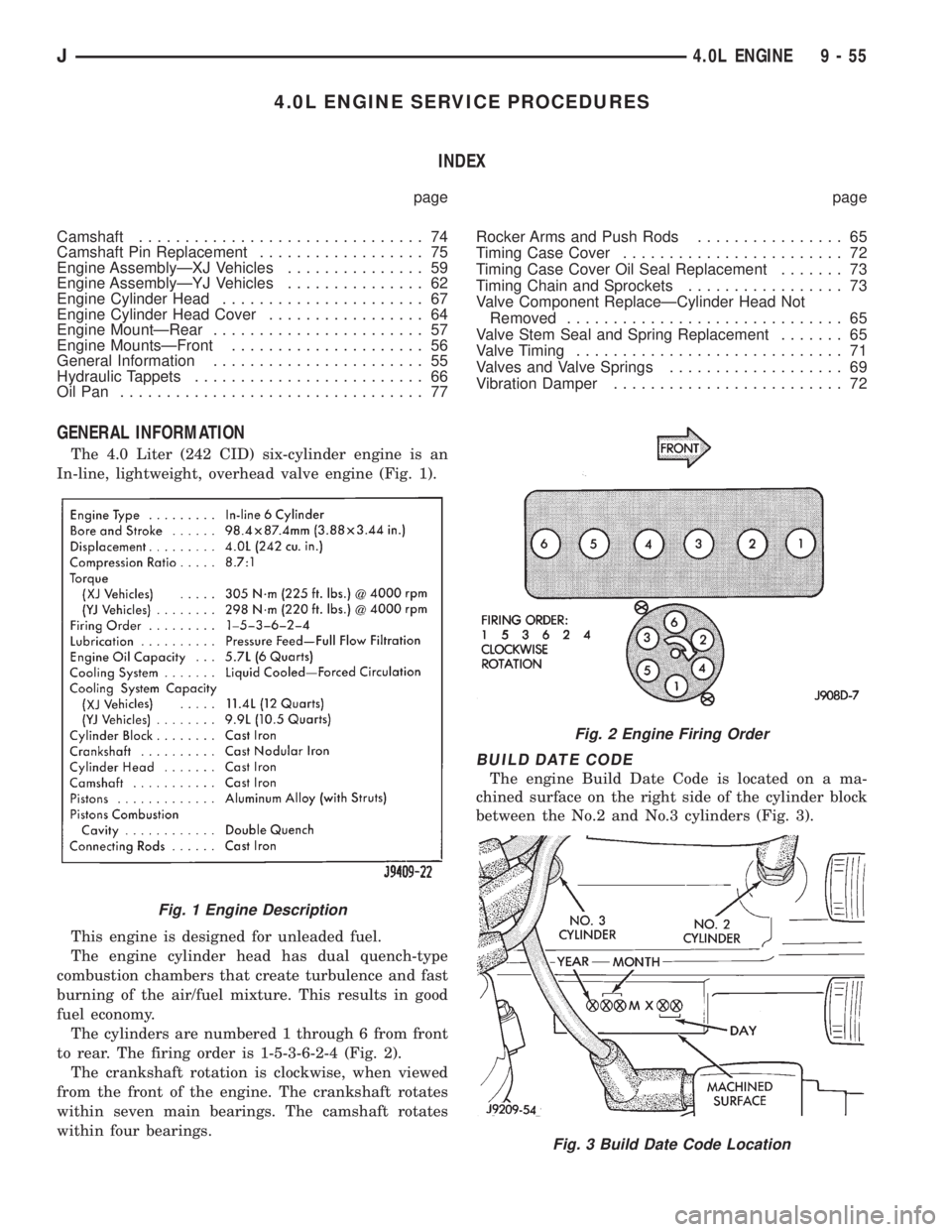
The 4.0 Liter (242 CID) six-cylinder engine is an
In-line, lightweight, overhead valve engine (Fig. 1).
This engine is designed for unleaded fuel.
The engine cylinder head has dual quench-type
combustion chambers that create turbulence and fast
burning of the air/fuel mixture. This results in good
fuel economy.
The cylinders are numbered 1 through 6 from front
to rear. The firing order is 1-5-3-6-2-4 (Fig. 2).
The crankshaft rotation is clockwise, when viewed
from the front of the engine. The crankshaft rotates
within seven main bearings. The camshaft rotates
within four bearings.
BUILD DATE CODE
The engine Build Date Code is located on a ma-
chined surface on the right side of the cylinder block
between the No.2 and No.3 cylinders (Fig. 3).
Fig. 1 Engine Description
Fig. 2 Engine Firing Order
Fig. 3 Build Date Code Location
J4.0L ENGINE 9 - 55
Page 1346 of 2158
LEAK-DOWN TEST
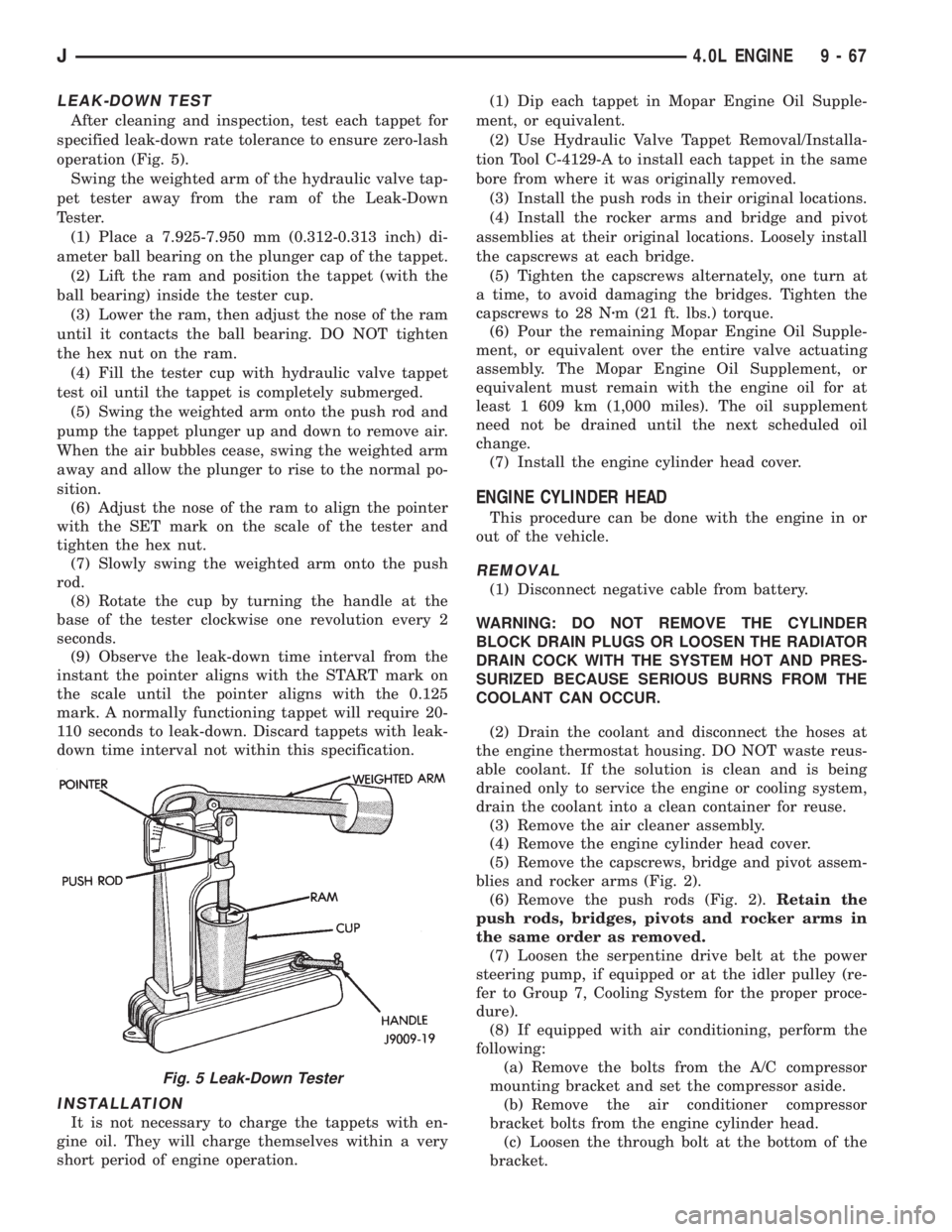
After cleaning and inspection, test each tappet for
specified leak-down rate tolerance to ensure zero-lash
operation (Fig. 5).
Swing the weighted arm of the hydraulic valve tap-
pet tester away from the ram of the Leak-Down
Tester.
(1) Place a 7.925-7.950 mm (0.312-0.313 inch) di-
ameter ball bearing on the plunger cap of the tappet.
(2) Lift the ram and position the tappet (with the
ball bearing) inside the tester cup.
(3) Lower the ram, then adjust the nose of the ram
until it contacts the ball bearing. DO NOT tighten
the hex nut on the ram.
(4) Fill the tester cup with hydraulic valve tappet
test oil until the tappet is completely submerged.
(5) Swing the weighted arm onto the push rod and
pump the tappet plunger up and down to remove air.
When the air bubbles cease, swing the weighted arm
away and allow the plunger to rise to the normal po-
sition.
(6) Adjust the nose of the ram to align the pointer
with the SET mark on the scale of the tester and
tighten the hex nut.
(7) Slowly swing the weighted arm onto the push
rod.
(8) Rotate the cup by turning the handle at the
base of the tester clockwise one revolution every 2
seconds.
(9) Observe the leak-down time interval from the
instant the pointer aligns with the START mark on
the scale until the pointer aligns with the 0.125
mark. A normally functioning tappet will require 20-
110 seconds to leak-down. Discard tappets with leak-
down time interval not within this specification.
INSTALLATION
It is not necessary to charge the tappets with en-
gine oil. They will charge themselves within a very
short period of engine operation.(1) Dip each tappet in Mopar Engine Oil Supple-
ment, or equivalent.
(2) Use Hydraulic Valve Tappet Removal/Installa-
tion Tool C-4129-A to install each tappet in the same
bore from where it was originally removed.
(3) Install the push rods in their original locations.
(4) Install the rocker arms and bridge and pivot
assemblies at their original locations. Loosely install
the capscrews at each bridge.
(5) Tighten the capscrews alternately, one turn at
a time, to avoid damaging the bridges. Tighten the
capscrews to 28 Nzm (21 ft. lbs.) torque.
(6) Pour the remaining Mopar Engine Oil Supple-
ment, or equivalent over the entire valve actuating
assembly. The Mopar Engine Oil Supplement, or
equivalent must remain with the engine oil for at
least 1 609 km (1,000 miles). The oil supplement
need not be drained until the next scheduled oil
change.
(7) Install the engine cylinder head cover.
ENGINE CYLINDER HEAD
This procedure can be done with the engine in or
out of the vehicle.
REMOVAL
(1) Disconnect negative cable from battery.
WARNING: DO NOT REMOVE THE CYLINDER
BLOCK DRAIN PLUGS OR LOOSEN THE RADIATOR
DRAIN COCK WITH THE SYSTEM HOT AND PRES-
SURIZED BECAUSE SERIOUS BURNS FROM THE
COOLANT CAN OCCUR.
(2) Drain the coolant and disconnect the hoses at
the engine thermostat housing. DO NOT waste reus-
able coolant. If the solution is clean and is being
drained only to service the engine or cooling system,
drain the coolant into a clean container for reuse.
(3) Remove the air cleaner assembly.
(4) Remove the engine cylinder head cover.
(5) Remove the capscrews, bridge and pivot assem-
blies and rocker arms (Fig. 2).
(6) Remove the push rods (Fig. 2).Retain the
push rods, bridges, pivots and rocker arms in
the same order as removed.
(7) Loosen the serpentine drive belt at the power
steering pump, if equipped or at the idler pulley (re-
fer to Group 7, Cooling System for the proper proce-
dure).
(8) If equipped with air conditioning, perform the
following:
(a) Remove the bolts from the A/C compressor
mounting bracket and set the compressor aside.
(b) Remove the air conditioner compressor
bracket bolts from the engine cylinder head.
(c) Loosen the through bolt at the bottom of the
bracket.
Fig. 5 Leak-Down Tester
J4.0L ENGINE 9 - 67
Page 1365 of 2158
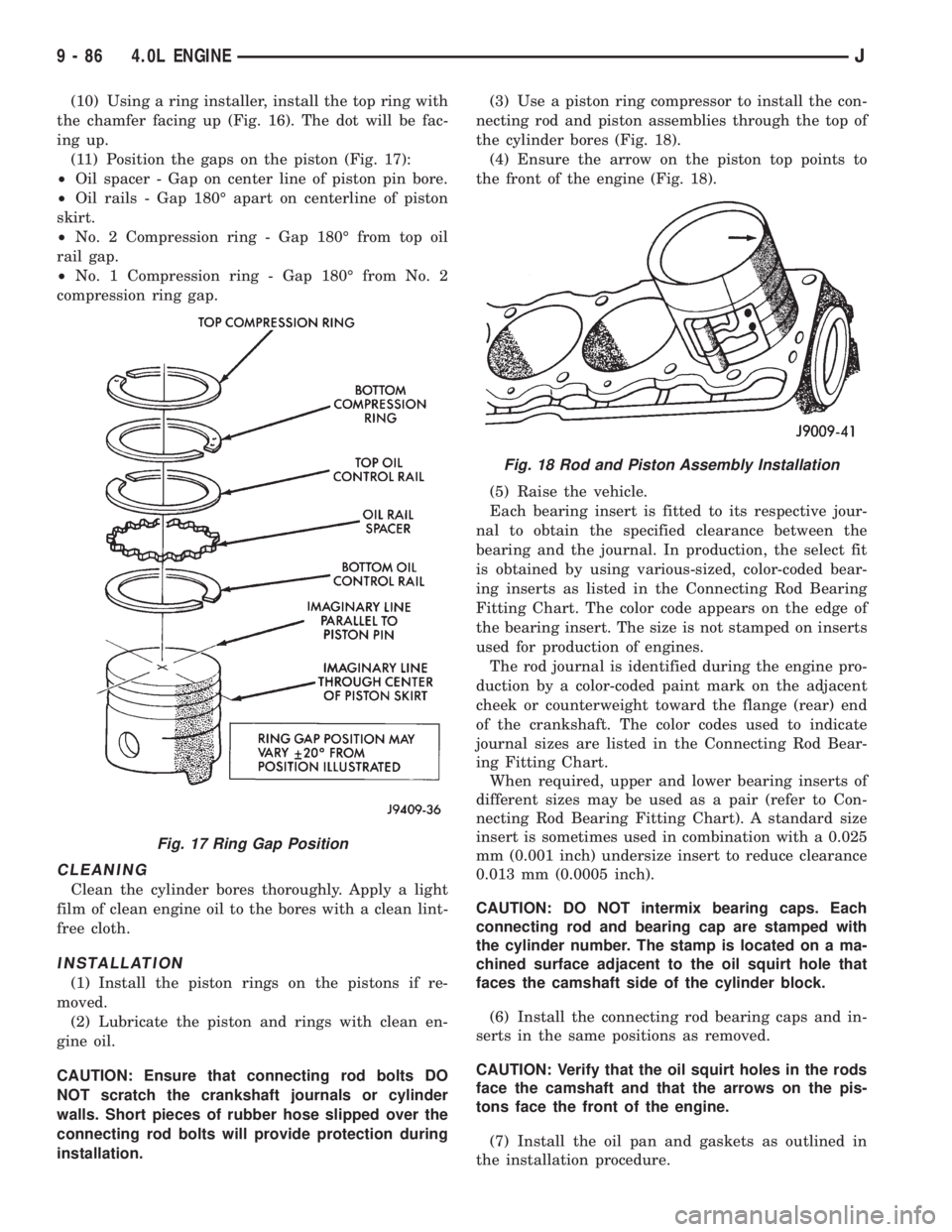
(10) Using a ring installer, install the top ring with
the chamfer facing up (Fig. 16). The dot will be fac-
ing up.
(11) Position the gaps on the piston (Fig. 17):
²Oil spacer - Gap on center line of piston pin bore.
²Oil rails - Gap 180É apart on centerline of piston
skirt.
²No. 2 Compression ring - Gap 180É from top oil
rail gap.
²No. 1 Compression ring - Gap 180É from No. 2
compression ring gap.
CLEANING
Clean the cylinder bores thoroughly. Apply a light
film of clean engine oil to the bores with a clean lint-
free cloth.
INSTALLATION
(1) Install the piston rings on the pistons if re-
moved.
(2) Lubricate the piston and rings with clean en-
gine oil.
CAUTION: Ensure that connecting rod bolts DO
NOT scratch the crankshaft journals or cylinder
walls. Short pieces of rubber hose slipped over the
connecting rod bolts will provide protection during
installation.(3) Use a piston ring compressor to install the con-
necting rod and piston assemblies through the top of
the cylinder bores (Fig. 18).
(4) Ensure the arrow on the piston top points to
the front of the engine (Fig. 18).
(5) Raise the vehicle.
Each bearing insert is fitted to its respective jour-
nal to obtain the specified clearance between the
bearing and the journal. In production, the select fit
is obtained by using various-sized, color-coded bear-
ing inserts as listed in the Connecting Rod Bearing
Fitting Chart. The color code appears on the edge of
the bearing insert. The size is not stamped on inserts
used for production of engines.
The rod journal is identified during the engine pro-
duction by a color-coded paint mark on the adjacent
cheek or counterweight toward the flange (rear) end
of the crankshaft. The color codes used to indicate
journal sizes are listed in the Connecting Rod Bear-
ing Fitting Chart.
When required, upper and lower bearing inserts of
different sizes may be used as a pair (refer to Con-
necting Rod Bearing Fitting Chart). A standard size
insert is sometimes used in combination with a 0.025
mm (0.001 inch) undersize insert to reduce clearance
0.013 mm (0.0005 inch).
CAUTION: DO NOT intermix bearing caps. Each
connecting rod and bearing cap are stamped with
the cylinder number. The stamp is located on a ma-
chined surface adjacent to the oil squirt hole that
faces the camshaft side of the cylinder block.
(6) Install the connecting rod bearing caps and in-
serts in the same positions as removed.
CAUTION: Verify that the oil squirt holes in the rods
face the camshaft and that the arrows on the pis-
tons face the front of the engine.
(7) Install the oil pan and gaskets as outlined in
the installation procedure.
Fig. 17 Ring Gap Position
Fig. 18 Rod and Piston Assembly Installation
9 - 86 4.0L ENGINEJ