1995 JEEP XJ transmission oil
[x] Cancel search: transmission oilPage 381 of 2158

The gauge needle moves as the movable permanent
magnet aligns itself to the changing magnetic fields
created around it by the electromagnets.
COOLANT TEMPERATURE GAUGE
The coolant temperature gauge gives an indication
of engine coolant temperature. The coolant tempera-
ture sending unit is a thermistor that changes elec-
trical resistance with changes in engine coolant
temperature. High sending unit resistance causes
low coolant temperature readings. Low resistance
causes high coolant temperature readings. Sending
unit resistance values are shown in a chart in Spec-
ifications.
FUEL GAUGE
The fuel gauge gives an indication of the level of
fuel in the fuel tank. The fuel gauge sending unit has
a float attached to a swing-arm in the fuel tank. The
float moves up or down within the fuel tank as fuel
level changes. As the float moves, an electrical con-
tact on the swing-arm wipes across a resistor coil,
which changes sending unit resistance. High sending
unit resistance causes high fuel level readings. Low
resistance causes low fuel level readings. Sending
unit resistance values are shown in a chart in Spec-
ifications.
OIL PRESSURE GAUGE
The oil pressure gauge gives an indication of en-
gine oil pressure. The combination oil pressure send-
ing unit contains a flexible diaphragm. The
diaphragm moves in response to changes in engine
oil pressure. As the diaphragm moves, sending unit
resistance increases or decreases. High resistance on
the gauge side of the sending unit causes high oil
pressure readings. Low resistance causes low oil
pressure readings. Sending unit resistance values are
shown in a chart in Specifications.
SPEEDOMETER/ODOMETER
The speedometer/odometer give an indication of ve-
hicle speed and travel distance. The speedometer re-
ceives a vehicle speed pulse signal from the Vehicle
Speed Sensor (VSS). An electronic integrated circuit
contained within the speedometer reads and analyzes
the pulse signal. It then adjusts the ground path re-
sistance of one electromagnet in the gauge to control
needle movement. It also sends signals to an electric
stepper motor to control movement of the odometer
number rolls. Frequency values for the pulse signal
are shown in a chart in Specifications.
The VSS is mounted to an adapter near the trans-
fer case output shaft. The sensor is driven through
the adapter by a speedometer pinion gear. The
adapter and pinion vary with transmission, axle ratio
and tire size. Refer to Group 21 - Transmission and
Transfer Case for more information.
TACHOMETER
The tachometer gives an indication of engine speed
in Revolutions-Per-Minute (RPM). With the engine
running, the tachometer receives an engine speed
pulse signal from the Powertrain Control Module
(PCM). An electronic integrated circuit contained
within the tachometer reads and analyzes the pulse
signal. It then adjusts the ground path resistance of
one electromagnet in the gauge to control needle
movement. Frequency values for the pulse signal are
shown in a chart in Specifications.
TRIP ODOMETER
The trip odometer is driven by the same electronic
integrated circuit as the speedometer/odometer. How-
ever, by depressing the trip odometer reset knob on
the face of the speedometer, the trip odometer can be
reset to zero. The trip odometer is serviced only as a
part of the speedometer/odometer gauge assembly.
VOLTMETER
The voltmeter is connected in parallel with the bat-
tery. With the ignition switch ON, the voltmeter in-
dicates battery or generator output voltage,
whichever is greater.
INDICATOR LAMPS
All indicator lamps, except the four-wheel drive in-
dicator, are located in the main cluster tell-tale area
above the steering column opening. Each of the
lamps is served by the main cluster printed circuit
and cluster connector. The four-wheel drive indicator
lamp is located in the gauge package cluster and is
served by the gauge package printed circuit and clus-
ter connector.
Up to eleven indicator lamps can be found in the
tell-tale area of the main cluster. These lamps are ar-
ranged in two rows, with six lamps in the upper row
and five lamps in the lower row.
ANTI-LOCK BRAKE SYSTEM LAMP
The Anti-Lock Brake System (ABS) lamp is
switched to ground by the ABS module. The module
lights the lamp when the ignition switch is turned to
the START position as a bulb test. The lamp will
stay on for 3 to 5 seconds after vehicle start-up to in-
dicate a system self-test is in process. If the lamp re-
mains on after start-up, or comes on and stays on
while driving, it may indicate that the ABS module
has detected a system malfunction or that the system
has become inoperative. Refer to Group 5 - Brakes
for more information.
BRAKE WARNING LAMP
The brake warning lamp warns the driver that the
parking brake is applied or that the pressures in the
two halves of the split brake hydraulic system are
unequal. With the ignition switch turned ON, battery
JINSTRUMENT PANEL AND GAUGESÐYJ 8E - 25
Page 384 of 2158

continuity. If OK, go to next step. If not OK, repair
circuit to ground as required.
(4) Remove center instrument cluster bezel and
gauge package cluster assembly. Disconnect cluster
connector.
(5) Probe cavity 6 of cluster connector. Check for
continuity to a good ground. There should be no con-
tinuity. If OK, go to next step. If not OK, repair short
circuit as required.
(6) Still probing cavity 6 of cluster connector, check
for continuity to cavity 2 of sending unit wiring body
half connector. There should be continuity. If OK, re-
place gauge. If not OK, repair open circuit as re-
quired.
OIL PRESSURE GAUGE
The diagnosis found here addresses an inoperative
gauge condition. If the problem being diagnosed is re-
lated to gauge accuracy, be certain to confirm that
problem is with gauge and not with engine oiling sys-
tem performance. Actual engine oil pressure should
be checked with a test gauge and compared to gauge
readings before you proceed with gauge diagnosis.
Refer to Group 9 - Engines for more information.
(1) Turn ignition switch to ON. Disconnect oil pres-
sure sending unit connector. The sending unit (Fig. 3)
is located on right side of engine block. On 2.5L en-
gine, it is just forward of ignition distributor and just
to the rear of generator mounting bracket. On 4.0L
engine, it is just to the rear of ignition distributor
and above oil filter adapter. The gauge needle should
move to high end of gauge scale. If OK, go to next
step. If not OK, go to step 3.
(2) Install a jumper wire from sending unit wiring
to ground. The gauge needle should move to low end
of gauge scale. If OK, replace sending unit. If not
OK, remove jumper wire and go to next step.(3) Turn ignition switch to OFF. Disconnect battery
negative cable. Remove center instrument cluster be-
zel and gauge package cluster assembly. Disconnect
cluster connector.
(4) Probe cavity 9 of cluster connector. Check for
continuity to a good ground. There should be no con-
tinuity. If OK, go to next step. If not OK, repair short
circuit as required.
(5) Still probing cavity 9 of cluster connector, check
for continuity to sending unit wire connector. There
should be continuity. If OK, replace gauge. If not OK,
repair open circuit as required.
SPEEDOMETER/ODOMETER
The diagnosis found here addresses an inoperative
gauge condition. If the problem being diagnosed is re-
lated to gauge accuracy, be certain to confirm that
problem is with gauge and not with incorrect speed-
ometer pinion, axle ratio or tire size. Refer to Group
21 - Transmission and Transfer Case for more infor-
mation.
(1) Perform vehicle speed sensor test as described
in the appropriate Powertrain Diagnostic Procedures
manual. If OK, go to next step. If not OK, replace ve-
hicle speed sensor.
(2) Disconnect battery negative cable. Unplug vehi-
cle speed sensor, PCM, and daytime running lamp
module connectors. Remove left instrument cluster
bezel and main cluster assembly. Disconnect cluster
connector.
(3) Probe cavity 13 of cluster connector. Check for
continuity to a good ground. There should be no con-
tinuity. If OK, go to next step. If not OK, repair short
circuit as required.
(4) Still probing cavity 13 of cluster connector,
check for continuity to cavity 1 of vehicle speed sen-
sor connector (Fig. 4). There should be continuity. If
OK, replace speedometer/odometer. If not OK, repair
open circuit as required.
Fig. 2 Fuel Gauge Sending Unit ConnectorFig. 3 Oil Pressure Sending Unit - Typical
8E - 28 INSTRUMENT PANEL AND GAUGESÐYJJ
Page 478 of 2158
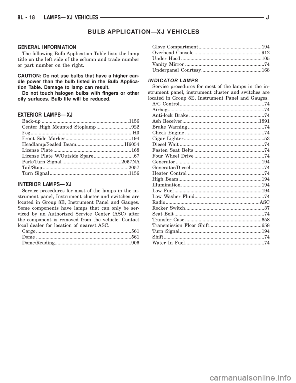
BULB APPLICATIONÐXJ VEHICLES
GENERAL INFORMATION
The following Bulb Application Table lists the lamp
title on the left side of the column and trade number
or part number on the right.
CAUTION: Do not use bulbs that have a higher can-
dle power than the bulb listed in the Bulb Applica-
tion Table. Damage to lamp can result.
Do not touch halogen bulbs with fingers or other
oily surfaces. Bulb life will be reduced.
EXTERIOR LAMPSÐXJ
Back-up .................................................................1156
Center High Mounted Stoplamp ..........................922
Fog ............................................................................H3
Front Side Marker .................................................194
Headlamp/Sealed Beam....................................H6054
License Plate ..........................................................168
License Plate W/Outside Spare ..............................67
Park/Turn Signal ............................................2057NA
Tail/Stop ................................................................2057
Turn Signal ...........................................................1156
INTERIOR LAMPSÐXJ
Service procedures for most of the lamps in the in-
strument panel, Instrument cluster and switches are
located in Group 8E, Instrument Panel and Gauges.
Some components have lamps that can only be ser-
viced by an Authorized Service Center (ASC) after
the component is removed from the vehicle. Contact
local dealer for location of nearest ASC.
Cargo .......................................................................561
Dome .......................................................................561
Dome/Reading.........................................................906Glove Compartment ...............................................194
Overhead Console ..................................................912
Under Hood ............................................................105
Vanity Mirror ...........................................................74
Underpanel Courtesy.............................................168
INDICATOR LAMPS
Service procedures for most of the lamps in the in-
strument panel, instrument cluster and switches are
located in Group 8E, Instrument Panel and Gauges.
A/C Control ...............................................................74
Airbag ........................................................................74
Anti-lock Brake ........................................................74
Ash Receiver .........................................................1891
Brake Warning .........................................................74
Check Engine ...........................................................74
Cigar Lighter ............................................................53
Diesel Wait ...............................................................74
Fasten Seat Belts ....................................................74
Four Wheel Drive ....................................................74
Generator ................................................................194
Generator/Diesel.......................................................74
Heater Control .........................................................74
High Beam..............................................................194
Illumination ............................................................194
Low Fuel .................................................................194
Low Washer Fluid....................................................74
Radio ......................................................................ASC
Rocker Switch...........................................................37
Seat Belt ...................................................................74
Transfer Case .........................................................658
Transmission Floor Shift.......................................658
Turn Signal.............................................................194
Shift ...........................................................................74
Water In Fuel ...........................................................74
8L - 18 LAMPSÐXJ VEHICLESJ
Page 585 of 2158
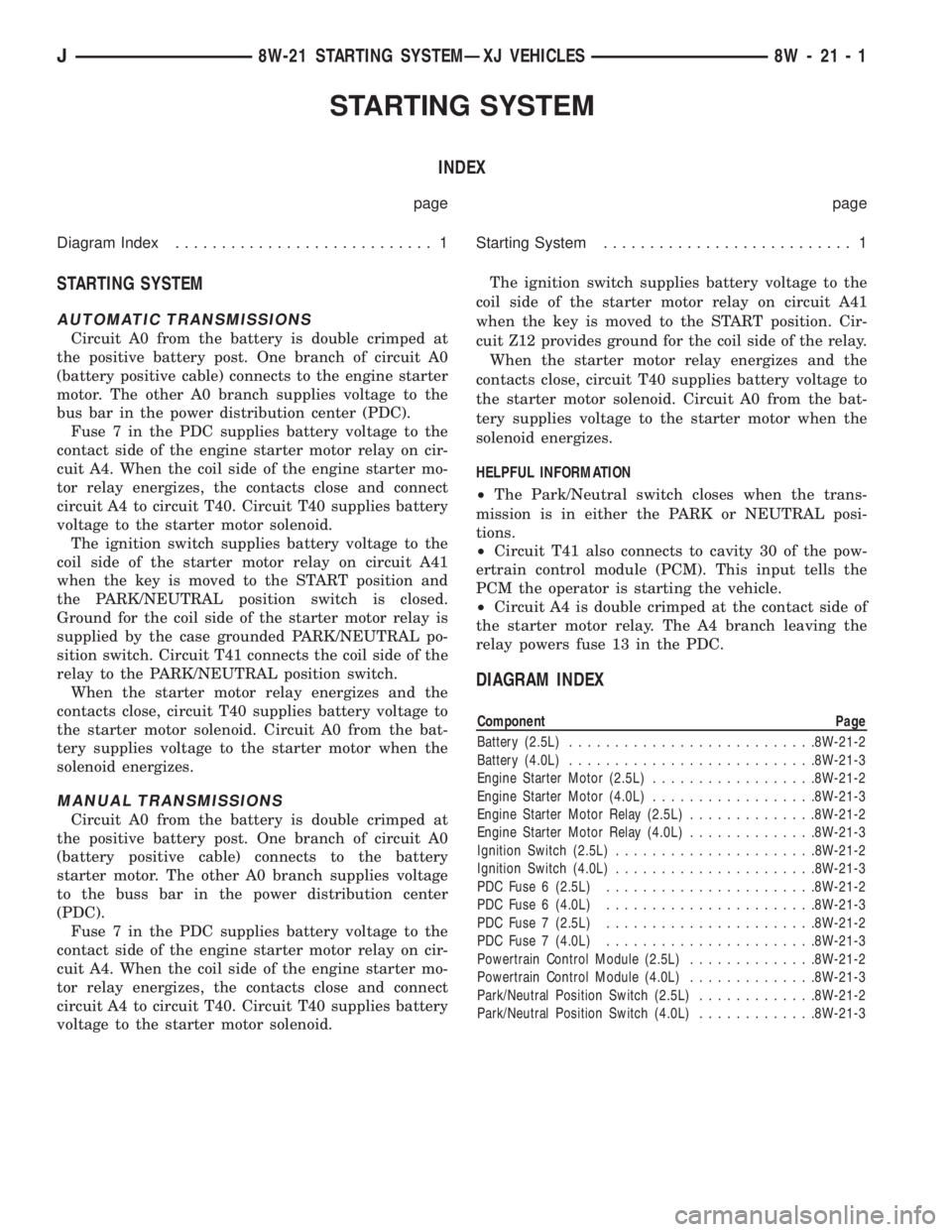
STARTING SYSTEM
INDEX
page page
Diagram Index............................ 1Starting System........................... 1
STARTING SYSTEM
AUTOMATIC TRANSMISSIONS
Circuit A0 from the battery is double crimped at
the positive battery post. One branch of circuit A0
(battery positive cable) connects to the engine starter
motor. The other A0 branch supplies voltage to the
bus bar in the power distribution center (PDC).
Fuse 7 in the PDC supplies battery voltage to the
contact side of the engine starter motor relay on cir-
cuit A4. When the coil side of the engine starter mo-
tor relay energizes, the contacts close and connect
circuit A4 to circuit T40. Circuit T40 supplies battery
voltage to the starter motor solenoid.
The ignition switch supplies battery voltage to the
coil side of the starter motor relay on circuit A41
when the key is moved to the START position and
the PARK/NEUTRAL position switch is closed.
Ground for the coil side of the starter motor relay is
supplied by the case grounded PARK/NEUTRAL po-
sition switch. Circuit T41 connects the coil side of the
relay to the PARK/NEUTRAL position switch.
When the starter motor relay energizes and the
contacts close, circuit T40 supplies battery voltage to
the starter motor solenoid. Circuit A0 from the bat-
tery supplies voltage to the starter motor when the
solenoid energizes.
MANUAL TRANSMISSIONS
Circuit A0 from the battery is double crimped at
the positive battery post. One branch of circuit A0
(battery positive cable) connects to the battery
starter motor. The other A0 branch supplies voltage
to the buss bar in the power distribution center
(PDC).
Fuse 7 in the PDC supplies battery voltage to the
contact side of the engine starter motor relay on cir-
cuit A4. When the coil side of the engine starter mo-
tor relay energizes, the contacts close and connect
circuit A4 to circuit T40. Circuit T40 supplies battery
voltage to the starter motor solenoid.The ignition switch supplies battery voltage to the
coil side of the starter motor relay on circuit A41
when the key is moved to the START position. Cir-
cuit Z12 provides ground for the coil side of the relay.
When the starter motor relay energizes and the
contacts close, circuit T40 supplies battery voltage to
the starter motor solenoid. Circuit A0 from the bat-
tery supplies voltage to the starter motor when the
solenoid energizes.
HELPFUL INFORMATION
²The Park/Neutral switch closes when the trans-
mission is in either the PARK or NEUTRAL posi-
tions.
²Circuit T41 also connects to cavity 30 of the pow-
ertrain control module (PCM). This input tells the
PCM the operator is starting the vehicle.
²Circuit A4 is double crimped at the contact side of
the starter motor relay. The A4 branch leaving the
relay powers fuse 13 in the PDC.
DIAGRAM INDEX
Component Page
Battery (2.5L)...........................8W-21-2
Battery (4.0L)...........................8W-21-3
Engine Starter Motor (2.5L)..................8W-21-2
Engine Starter Motor (4.0L)..................8W-21-3
Engine Starter Motor Relay (2.5L)..............8W-21-2
Engine Starter Motor Relay (4.0L)..............8W-21-3
Ignition Switch (2.5L)......................8W-21-2
Ignition Switch (4.0L)......................8W-21-3
PDC Fuse 6 (2.5L).......................8W-21-2
PDC Fuse 6 (4.0L).......................8W-21-3
PDC Fuse 7 (2.5L).......................8W-21-2
PDC Fuse 7 (4.0L).......................8W-21-3
Powertrain Control Module (2.5L)..............8W-21-2
Powertrain Control Module (4.0L)..............8W-21-3
Park/Neutral Position Switch (2.5L).............8W-21-2
Park/Neutral Position Switch (4.0L).............8W-21-3
J8W-21 STARTING SYSTEMÐXJ VEHICLES 8W - 21 - 1
Page 592 of 2158

The PCM provides a ground for the engine coolant
temperature sensor signal (circuit K2) through circuit
K4. Circuit K4 connects to cavity 4 of the PCM con-
nector.
HELPFUL INFORMATION
Circuit K4 splices to supply ground for the signals
from the following:
²Heated oxygen sensor
²Camshaft position sensor
²Crankshaft position sensor
²Intake air temperature sensor
²Throttle position sensor
²Manifold absolute pressure sensor
²Engine coolant temperature sensor
²Vehicle speed sensor
THROTTLE POSITION SENSOR
From the Powertrain Control Module (PCM), cir-
cuit K6 supplies 5 volts to the throttle position sen-
sor (TPS). Circuit K6 connects to cavity 6 of the
PCM.
Circuit K22 delivers the TPS signal to the PCM.
Circuit K22 connects to cavity 22 of the PCM.
The PCM provides a ground for the throttle posi-
tion sensor signal (circuit K22) through circuit K4.
Circuit K4 connects to cavity 4 of the PCM.
HELPFUL INFORMATION
Refer to Group 14 for throttle position sensor oper-
ation.
Circuit K6 splices to supply 5 volts to the manifold
absolute pressure sensor.
On vehicles equipped with the 4.0L engine and au-
tomatic transmission, circuit K22 splices to the
transmission control module.
Circuit K4 splices to supply ground for the signals
from the following:
²Heated oxygen sensor
²Camshaft position sensor
²Crankshaft position sensor
²Intake air temperature sensor
²Throttle position sensor
²Manifold absolute pressure sensor
²Engine coolant temperature sensor
²Vehicle speed sensor
MANIFOLD ABSOLUTE PRESSURE SENSOR
From the Powertrain Control Module (PCM), cir-
cuit K6 supplies 5 volts to the manifold absolute
pressure (MAP) sensor. Circuit K6 connects to cavity
6 of the PCM.
Circuit K1 delivers the MAP signal to the PCM.
Circuit K1 connects to cavity 1 of the PCM.
The PCM provides a ground for the MAP sensor
signal (circuit K1) through circuit K4. Circuit K4 con-
nects to cavity 4 of the PCM.
HELPFUL INFORMATION
Refer to Group 14 for MAP sensor operation.
Circuit K6 splices to supply 5 volts to the throttle
position sensor.
Circuit K4 splices to supply ground for the signals
from the following:
²Heated oxygen sensor
²Camshaft position sensor
²Crankshaft position sensor
²Intake air temperature sensor
²Throttle position sensor
²Manifold absolute pressure sensor
²Engine coolant temperature sensor
²Vehicle speed sensor
INTAKE AIR TEMPERATURE SENSOR
The intake air temperature sensor provides an in-
put to the Powertrain Control Module (PCM) on cir-
cuit K21. Circuit K21 connects to cavity 21 of the
PCM.
From circuit K21, the intake air temperature sen-
sor draws voltage from the PCM. The sensor is a
variable resistor. As intake air temperature changes,
the resistance in the sensor changes, causing a
change in current draw.
The PCM provides a ground for the intake air tem-
perature sensor signal (circuit K21) through circuit
K4. Circuit K4 connects to cavity 4 of the PCM.
HELPFUL INFORMATION
Circuit K4 splices to supply ground for the signals
from the following:
²Heated oxygen sensor
²Camshaft position sensor
²Crankshaft position sensor
²Intake air temperature sensor
²Throttle position sensor
²Manifold absolute pressure sensor
²Engine coolant temperature sensor
²Vehicle speed sensor
PARK/NEUTRAL POSITION SWITCH
When closed, the case-grounded park/neutral posi-
tion switch provides a ground path on circuit T41 for
the coil side of the starter motor relay. Circuit A41
from the ignition switch provides battery voltage to
the coil side of the relay.
Circuit T41 splices to cavity 30 of the PCM. The
park/neutral position switch provides an input to the
Powertrain Control Module (PCM).
TORQUE CONVERTER CLUTCH (TCC) SOLENOID
AND RELAY
The TCC solenoid is only used on 2.5L engines
with the three-speed automatic transmissions. The
Powertrain Control Module (PCM) operates the TCC
solenoid by energizing the TCC relay.
8W - 30 - 4 8W-30 FUEL/IGNITIONÐXJ VEHICLESJ
Page 593 of 2158

Circuit T17 from fuse 3 in the power distribution
center supplies voltage to the coil and contact sides
of the TCC relay. When the PCM provides a ground
path on circuit K54 for the coil side of the relay, the
relay contacts close.
When the relay contacts close, they connect circuit
T17 with circuit T22. Circuit T22 supplies battery
voltage to the case grounded TCC solenoid. Circuit
K54 connects to PCM cavity 54.
HELPFUL INFORMATION
²In the RUN or START position, the ignition switch
connects circuit A1 from fuse 4 in the PDC to circuit
A21.
UPSHIFT LAMP
On vehicles equipped with a manual transmission,
the PCM grounds the up-shift lamp on circuit K54.
Circuit K54 connects to cavity 54 of the PCM.
POWER STEERING PRESSURE SWITCH
The PCM supplies voltage to the power steering
pressure switch on circuit K10. Circuit Z12 provides
ground for the switch. When the switch closes, volt-
age flows through the switch to ground on circuit
Z12. The switch closes during periods of high power
steering pump load and low engine speed; such as
parking maneuvers.
Circuit K10 connects to cavity 10 of the PCM. Cir-
cuit Z12 terminates at the right rear of the engine.
TACHOMETER SIGNAL
The PCM supplies the signal for the tachometer on
circuit G21. Circuit G21 connects to cavity 43 of the
PCM.
MALFUNCTION INDICATOR LAMP (MIL)
The PCM provides ground for the instrument clus-
ter malfunction indicator lamp on circuit G3. The
MIL displays the message CHECK ENGINE when il-
luminated. Circuit F87 provides voltage for the lamp.
DATA LINK CONNECTOR
Circuit F12 supplies battery voltage to the data
link connector. Circuit F12 originates at fuse 11 in
the Power Distribution Center.
Circuit D20 connects to cavity 45 of the PCM. Cir-
cuit D20 is the SCI receive circuit for the PCM.
Circuit D21 connects to cavity 25 of the PCM. Cir-
cuit D21 is the SCI transmit circuit for the PCM.
Circuit Z11 provides ground for the data link con-
nector. Circuit Z11 terminates at the right rear of the
engine. Circuit Z11 also connects to cavity 5 of the
PCM.
HELPFUL INFORMATION
²Circuit Z1 also supplies a ground for the PCM
high current drivers.
²If the system loses ground for the Z11 circuits at
the right rear of the engine, the vehicle will not op-
erate. Check the connection at the ganged-ground cir-
cuit eyelet.
²Circuit F12 splices to supply battery voltage to the
vehicle speed control switch, back-up lamp switch,
A/C compressor clutch relay, windshield washer fluid
level sensor and radiator fan relay (4.0L engines).
BRAKE SWITCH INPUT
Circuit K29 provides the brake switch input to the
PCM. Circuit V40 connects to cavity 29 of the PCM.
POWER (DEVICE) GROUND
Circuit Z12 connects to cavities 11 and 12 of the
PCM. The Z12 circuit provides ground for PCM inter-
nal drivers that operate high current devices like the
injectors and ignition coil.
Internal to the PCM, the power (device) ground cir-
cuit connects to the PCM sensor return circuit (from
circuit K4).
HELPFUL INFORMATION
²The grounding point for circuit Z12 is the right
rear of the engine.
²If the system loses ground for the Z12 circuits at
the rear of the engine, the vehicle will not operate.
Check the connection at the ganged-ground circuit
eyelet.
²On vehicles equipped with the 4.0L engine and au-
tomatic transmission, circuit Z12 splices to provide
ground for the transmission control module.
EXTENDED IDLE SWITCH
On Police Package vehicles, an optional extended
idle switch provides an input to the Powertrain Con-
trol Module (PCM) on circuit K10. Circuit K10 con-
nects to cavity 10 of the PCM. Circuit F60 supplies
battery voltage to the extended idle switch. Circuit
Z1 grounds the switch.
CCD BUS
On vehicles equipped with the 4.0L engine, circuits
D1 and D2 connect the Powertrain Control Module
(PCM) to the CCD Bus. Circuit D1 connects to cavity
26 of the PCM. Circuit D2 connects to cavity 46 of
the PCM. Circuits D1 and D2 are a twisted pair of
wires.
J8W-30 FUEL/IGNITIONÐXJ VEHICLES 8W - 30 - 5
Page 609 of 2158

TRANSMISSION CONTROLS
UPSHIFT LAMP
On vehicles equipped with a manual transmission,
the PCM grounds the up-shift lamp on circuit K54.
Circuit K54 connects to cavity 54 of the PCM.
FOUR-WHEEL DRIVE (4WD) SWITCH
When the 4WD switch closes, circuit Z1 provides
ground for the 4WD indicator lamp in the instrument
cluster. Circuit F87 connects to the instrument clus-
ter and supplies battery voltage to the 4WD indicator
lamp. Circuit 107 connects the indicator lamp to the
4WD switch. Circuit 106 connects the lamp to the in-
strument cluster and circuit F87.
TRANSMISSION CONTROL MODULEÐ4.0L
ENGINE ONLY
Vehicles equipped with the 4.0L engine have elec-
tronically controlled solenoids in the automatic trans-
mission valve body.
The Transmission Control Module (TCM) receives
inputs from the Throttle Position Sensor (TPS) on
circuit K22 and the stop lamp switch on circuit K29.
Circuit K4 connects to the TCM to provide ground for
the TPS signal. The TCM receives the transmission
output speed sensor signal on circuit T505. Circuit
A14 from fuse 2 in the Power Distribution Center
supplies battery voltage to the TCM. Circuit Z12 pro-
vides ground for the TCM.
The TCM powers the S1 solenoid on circuit T510,
the S2 solenoid on circuit T509, and the S3 solenoid
on circuit T508. Circuit Z12 provides ground for the
S1, S2, and S3 solenoids.
TORQUE CONVERTER CLUTCH (TCC) SOLENOID
AND RELAYÐ2.5L ENGINE ONLY
The TCC solenoid is only used on 2.5L engines
with the three-speed automatic transmissions. The
Powertrain Control Module (PCM) operates the TCC
solenoid by energizing the TCC relay.
Circuit T17 from fuse 12 in the Power Distribution
Center (PDC) supplies voltage to the coil and contact
sides of the TCC relay. When the PCM provides a
ground path on circuit K54 for the coil side of the re-
lay, the relay contacts close.
When the relay contacts close, they connect circuit
T17 with circuit T22. Circuit T22 supplies battery
voltage to the case grounded TCC solenoid. Circuit
K54 connects to PCM cavity 54.
HELPFUL INFORMATION
²In the RUN or START position, the ignition switch
connects circuit A1 from fuse 6 in the PDC to circuit
A21.
DIAGRAM INDEX
Component Page
4-WD Indicator Lamp......................8W-31-4
4-WD Indicator Switch.....................8W-31-4
Back-Up Lamp Switch.....................8W-31-3
Fuse 2 (PDC)...........................8W-31-4
Fuse 6 (PDC).........................8W-31-2, 3
Fuse 11 (PDC)..........................8W-31-3
Fuse 12 (PDC)..........................8W-31-2
Ignition Switch........................8W-31-2, 3
Powertrain Control Module..................8W-31-2
Park/Neutral Position Switch.................8W-31-3
TCC Relay.............................8W-31-2
TCC Solenoid...........................8W-31-2
Transmission Control Module.................8W-31-2
J8W-31 TRANSMISSION CONTROLSÐXJ VEHICLES 8W - 31 - 1
Page 625 of 2158

INSTRUMENT CLUSTER
INDEX
page page
ABS Warning Lamp........................ 2
Brake Warning Lamp....................... 2
Charging System Indicator Lamp............... 3
Cluster Ground............................ 3
Diagram Index............................. 3
Engine Coolant Temperature Gauge............ 1
Engine Coolant Temperature Warning Lamp...... 1
Fuel Gauge.............................. 1
High-Beam Indicator Lamp................... 2
Instrument Cluster......................... 1Low Fuel Warning Lamp..................... 1
Low Washer Fluid Warning Lamp.............. 2
Malfunction Indicator Lamp (MIL)............... 2
Manual Transmission Up-Shift Lamp............ 2
Oil Pressure Gauge........................ 2
Oil Pressure Warning Lamp.................. 2
Seat Belt Indicator Warning Lamp.............. 2
Speedometer............................. 2
Tachometer.............................. 2
Turn Signal Indicator Lamps.................. 2
INSTRUMENT CLUSTER
The instrument cluster contains the gauges and
warning lamps. All gauges have magnetic move-
ments.
When the ignition switch is in the START or RUN
position, circuit A21 feeds circuit F87 through fuse 17
in the fuse block. Circuit A1 from fuse 6 in the Power
Distribution Center (PDC) supplies voltage to circuit
A21. Circuit A1 is HOT at all times.
Circuit F87 connects to the cluster connector to
power the gauges and to the telltale connector to
power the warning lamps.
Circuit E2 from fuse 19 in the fuse block feeds the
illumination lamps. Circuit E2 originates at the head-
lamp switch and continues through fuse 19. The
headlamp switch powers circuit E2 when the parking
lamps or headlamp are ON.
Circuit Z2 provides ground for the indicator lamps
and illumination lamps.
ENGINE COOLANT TEMPERATURE GAUGE
Circuit G20 connects the engine coolant tempera-
ture gauge to the engine coolant temperature sensor.
The sensor is a variable resistor and case grounded to
the engine. Circuit F87 connects to the instrument
cluster left connector and supplies voltage for the
gauge.
The gauge uses two coils. Current passing through
the coils creates a magnetic field. Position of the
gauge needle is controlled by the amount of current
passing through the coils to ground at the sensor.
ENGINE COOLANT TEMPERATURE WARNING
LAMP
Circuit G20 connects the engine coolant tempera-
ture warning lamp to the engine coolant temperature
switch. When the switch closes, battery voltage from
circuit F87 flows through the lamp to ground through
the switch on circuit G20. The engine coolant tem-
perature switch is case grounded to the engine. Cir-cuit F87 connects to the instrument cluster connector
and supplies voltage for the lamp.
Circuit G20 also connects to the warning lamp to
ground when the ignition switch is in the START
position. When the ignition switch is in the START
position, the lamp illuminates for a bulb test.
FUEL GAUGE
The fuel level sensor is a variable resistor. Circuit
G4 connects the fuel level sensor to the fuel gauge in
the instrument cluster. Circuit F87 from fuse 17 in
the fuse block supplies voltage to the fuel gauge. The
fuel level sensor draws voltage from circuit F87
through the fuel gauge on circuit G4. Circuit G4
connects to circuit 57 in the fuel pump module har-
ness. Circuit 57 connects to the fuel level sensor.
Circuit 99 in the fuel pump module harness con-
nects to circuit Z1. Circuit Z1 provides the ground
path for the fuel level sensor. The grounding point for
circuit Z1 is the left side of the cowl panel.
As current flows through the coils in the fuel gauge,
it creates a magnetic field. One of the coils in the
gauge receives fixed current. The other coil is con-
nected to the level sensor. The magnetic field controls
the position of the fuel gauge pointer.
The fuel level sensor contains a variable resistor. As
the position of the float arm on the fuel level sensor
changes, the resistor changes the current flow
through second coil in the fuel gauge. A change in
current flow alters the magnetic field in the fuel
gauge, which changes the pointer position.
LOW FUEL WARNING LAMP
Circuit G4 connects the fuel level sensor to the fuel
gauge. The low fuel level module at the rear of the
gauge monitors resistance in circuit G4. The low fuel
level module powers an light emitting diode (LED)
when the resistance in circuit G4 reaches a calibrated
level. The LED illuminates the Low Fuel indicator.
Refer to Group 8E for additional information.
J8W-40 INSTRUMENT CLUSTERÐXJ VEHICLES 8W - 40 - 1