1995 JEEP XJ steering wheel
[x] Cancel search: steering wheelPage 187 of 2158

ABS DIAGNOSTIC CONNECTOR
The ABS diagnostic connector is inside the vehicle.
The connector is the access point for the DRB scan
tool.
On XJ models, the connector is located under the
instrument panel to the right of the steering column.
On some models, the connecter may be tucked under
the carpeting on the transmission tunnel. The con-
necter is a black, 6-way type.
On YJ models, the connector is under the instru-
ment panel by the the driver side kick panel. The
connecter is a black, 6 or 8-way type.
The DRB scan tool kit contains adapter cords for
both types of connecter. Use the appropriate cord for
test hookup.
ACCELERATION SWITCH
An acceleration switch (Fig. 5), provides an addi-
tional vehicle deceleration reference during 4-wheel
drive operation. The switch is monitored by the an-
tilock ECU at all times. The switch reference signal
is utilized by the ECU when all wheels are deceler-
ating at the same speed.
SYSTEM RELAYS
The ABS system has two relays, which are the
main and motor pump relays. The motor pump relay
is used for the motor pump only. The main relay is
used for the solenoid valves and ECU. The main re-
lay is connected to the ECU at the power control re-
lay terminal. The pump motor relay starts/stops the
pump motor when signaled by the ECU.
IGNITION SWITCH
The antilock ECU and warning light are in standby
mode with the ignition switch in Off or Accessory po-
sition. No operating voltage is supplied to the system
components.A 12 volt power feed is supplied to the ECU and
warning light when the ignition switch is in the Run
position.
SYSTEM WARNING LIGHT
The amber ABS warning light is in circuit with the
ECU and operates independently of the red brake
warning light.
The ABS light indicates antilock system condition.
The light illuminates (flashes) at start-up for the self
check. The light goes out when the self check pro-
gram determines system operation is normal.
ABS SYSTEM POWER-UP AND INITIALIZATION
battery voltage is supplied to the ECU ignition ter-
minal when the ignition switch is turned to Run po-
sition. The ECU performs a system initialization
procedure at this point. Initialization consists of a
static and dynamic self check of system electrical
components.
The static check occurs after the ignition switch is
turned to Run position. The dynamic check occurs
when vehicle road speed reaches approximately 10
kph (6 mph). During the dynamic check, the ECU
briefly cycles the pump and solenoids to verify oper-
ation.
If an ABS component exhibits a fault during initial-
ization, the ECU illuminates the amber warning
light and registers a fault code in the microprocessor
memory.
ABS OPERATION IN NORMAL BRAKING MODE
The ECU monitors wheel speed sensor inputs con-
tinuously while the vehicle is in motion. However,
the ECU will not activate any ABS components as
long as sensor inputs and the acceleration switch in-
dicate normal braking.
Fig. 4 Wheel Speed SensorsFig. 5 Acceleration Switch
JABS OPERATION AND SERVICE 5 - 35
Page 188 of 2158

During normal braking, the master cylinder, power
booster and wheel brake units all function as they
would in a vehicle without ABS. The HCU compo-
nents are not activated.
ABS OPERATION IN ANTILOCK BRAKING MODE
The purpose of the antilock system is to prevent
wheel lockup during periods of high wheel slip. Pre-
venting lockup helps maintain vehicle braking action
and steering control.
The antilock ECU activates the system whenever
sensor signals indicate periods of high wheel slip.
High wheel slip can be described as the point where
wheel rotation begins approaching zero (or lockup)
during braking. Periods of high wheel slip may occur
when brake stops involve high pedal pressure and
rate of deceleration.
The antilock system prevents lockup during high
slip conditions by modulating fluid apply pressure to
the wheel brake units.
Brake fluid apply pressure is modulated according
to wheel speed, degree of slip and rate of decelera-
tion. A sensor at each wheel converts wheel speed
into electrical signals. These signals are transmitted
to the ECU for processing and determination of
wheel slip and deceleration rate.
The ABS system has three fluid pressure control
channels. The front brakes are controlled separately
and the rear brakes in tandem (Fig. 1). A speed sen-
sor input signal indicating a high slip condition acti-
vates the ECU antilock program.
Two solenoid valves are used in each antilock con-
trol channel. The valves are all located within the
HCU valve body and work in pairs to either increase,
hold, or decrease apply pressure as needed in the in-
dividual control channels.
The solenoid valves are not static during antilock
braking. They are cycled continuously to modulate
pressure. Solenoid cycle time in antilock mode can be
measured in milliseconds.
HCU OPERATION
Normal Braking
During normal braking, the HCU solenoid valves
and pump are not activated. The master cylinder and
power booster operate the same as a vehicle without
an ABS brake system.
Antilock Pressure Modulation
Solenoid valve pressure modulation occurs in three
stages which are: pressure increase, pressure hold,
and pressure decrease. The valves are all contained
in the valve body portion of the HCU.
Pressure Decrease
The outlet valve is opened and the inlet valve is
closed during the pressure decrease cycle (Fig. 6).A pressure decrease cycle is initiated when speed
sensor signals indicate high wheel slip at one or
more wheels. At this point, the ECU opens the outlet
valve, which also opens the return circuit to the ac-
cumulators. Fluid pressure is allowed to bleed off (de-
crease) as needed to prevent wheel lock.
Once the period of high wheel slip has ended, the
ECU closes the outlet valve and begins a pressure in-
crease or hold cycle as needed.
Pressure Hold
Both solenoid valves are closed in the pressure hold
cycle (Fig. 7). Fluid apply pressure in the control
channel is maintained at a constant rate. The ECU
maintains the hold cycle until sensor inputs indicate
a pressure change is necessary.
Pressure Increase
The inlet valve is open and the outlet valve is
closed during the pressure increase cycle (Fig. 8). The
pressure increase cycle is used to counteract unequal
wheel speeds. This cycle controls re-application of
fluid apply pressure due to changing road surfaces or
wheel speed.
Fig. 6 Pressure Decrease Cycle
5 - 36 ABS OPERATION AND SERVICEJ
Page 189 of 2158

WHEEL SPEED SENSOR OPERATION
Wheel speed input signals are generated by a sen-
sor and tone ring at each wheel. The sensors, which
are connected directly to the ECU, are mounted on
brackets attached to the front steering knuckles and
rear brake support plates.
The sensor triggering devices are the tone rings
which are similar in appearance to gears. The tone
rings are located on the outboard end of each front/rear axle shaft. The speed sensors generate a signal
whenever a tone ring tooth rotates past the sensor
pickup face.
The wheel speed sensors provide the input signal
to the ECU. If input signals indicate ABS mode brak-
ing, the ECU causes the HCU solenoids to decrease,
hold, or increase fluid apply pressure as needed.
The HCU solenoid valves are activated only when
wheel speed input signals indicate that a wheel is
approaching a high slip, or lockup condition. At this
point, the ECU will cycle the appropriate wheel con-
trol channel solenoid valves to prevent lockup.
The wheel sensors provide speed signals whenever
the vehicle wheels are rotating. The ECU examines
these signals for degree of deceleration and wheel
slip. If signals indicate normal braking, the solenoid
valves are not activated. However, when incoming
signals indicate the approach of wheel slip, or lockup,
the ECU cycles the solenoid valves as needed.
ACCELERATION SWITCH OPERATION
The ECU monitors the acceleration switch at all
times. The switch assembly contains three mercury
switches that monitor vehicle ride height and decel-
eration rates (G-force). Sudden, rapid changes in ve-
hicle and wheel deceleration rate, triggers the switch
sending a signal to the ECU. The switch assembly
provides three deceleration rates; two for forward
braking and one for rearward braking.
ECU OPERATION
The antilock ECU controls all phases of antilock
operation. It monitors and processes input signals
from the system sensors.
It is the ECU that activates the solenoid valves to
modulate apply pressure during antilock braking.
The ECU program is able to determine which wheel
control channel requires modulation and which fluid
pressure modulation cycle to use. The ECU cycles the
solenoid valves through the pressure decrease, hold
and increase phases.
ABS COMPONENT SERVICEABILITY
The ECU, acceleration sensor, wheel sensors, and
wire harnesses are serviced as assemblies only. The
axle shaft tone wheels are also not serviceable. If a
tone wheel becomes damaged, it will be necessary to
replace the axle shaft, or disc brake rotor and hub
assembly.
SPEED SENSOR AIR GAP
Front sensor air gap is fixed and not adjustable.
Only rear sensor air gap is adjustable.
Although front air gap is not adjustable, it can be
checked if diagnosis indicates this is necessary. Front
Fig. 7 Pressure Hold Cycle
Fig. 8 Pressure Increase Cycle
JABS OPERATION AND SERVICE 5 - 37
Page 190 of 2158

air gap should be 0.40 to 1.3 mm (0.0157 to 0.051
in.). If gap is incorrect, the sensor is either loose, or
damaged.
A rear sensor air gap adjustment is only needed
when reinstalling an original sensor. Replacement
sensors have an air gap spacer attached to the sensor
pickup face. The spacer establishes correct air gap
when pressed against the tone ring during installa-
tion. As the tone ring rotates, it peels the spacer off
the sensor to create the required air gap. Rear sensor
air gap is 0.92-1.45 mm (0.036-0.057 in.).
Sensor air gap measurement, or adjustment proce-
dures are provided in this section. Refer to the front,
or rear sensor removal and installation procedures as
required.
FRONT WHEEL SENSOR REMOVAL
(1) Raise vehicle and turn wheel outward for easier
access to sensor.
(2) Remove sensor wire from mounting brackets.
(3) Clean sensor and surrounding area with shop
towel before removal.
(4) Remove bolt attaching sensor to steering
knuckle and remove sensor.
(5) remove sensor wire from brackets on body and
steering knuckle.
(6) Unseat sensor wire grommet in wheel house
panel.
(7) In engine compartment, disconnect sensor wire
connector at harness plug. Then remove sensor and
wire.
FRONT WHEEL SENSOR INSTALLATION
(1) Iforiginalsensor will be installed, wipe all
traces of old spacer material off sensor pickup face.
Use a dry shop towel for this purpose.
(2) Apply Mopar Lock N' Seal or Loctite 242 to bolt
that secures sensor in steering knuckle. Use new
sensor bolt if original bolt is worn or damaged.
(3) Position sensor on steering knuckle. Seat sen-
sor locating tab in hole in knuckle and install sensor
attaching bolt finger tight.
(4) Tighten sensor attaching bolt to 14 Nzm (11 ft.
lbs.) torque.
(5) If original sensor has been installed, check sen-
sor air gap. Air gap should be 0.40 to 1.3 mm (0.0157
to 0.051 in.). If gap is incorrect, sensor is either loose,
or damaged.
(6) Secure sensor wire to steering knuckle and
body brackets.
(7) Route sensor wire forward and behind shock
absorber. Then attach sensor wire to spring seat
bracket with grommets on sensor wire.
(8) Route sensor wire to outer sill bracket. Remove
all twists or kinks from wire.
(9) Attach sensor wire to sill bracket with grom-
met. Be sure wire is free of twists and kinks.(10) Verify sensor wire routing. Wire should loop
forward and above sill bracket. Loose end of wire
should be below sill bracket and towards brake hose.
(11) Seat sensor wire grommet in body panel and
clip wire to brake line at grommet location.
(12) Connect sensor wire to harness in engine com-
partment.
REAR WHEEL SENSOR REMOVAL
(1) On XJ models, raise and fold rear seat forward
for access to rear sensor connectors (Fig. 9).
(2) Disconnect sensors at rear harness connectors.
(3) Push sensor grommets and sensor wires
through floorpan.
(4) Raise vehicle.
(5) Disconnect sensor wires at rear axle connectors.
(6) Remove wheel and tire assembly.
(7) Remove brake drum.
(8) Remove clips securing sensor wires to brake-
lines, rear axle and, brake hose.
(9) Unseat sensor wire support plate grommet.
(10) Remove bolt attaching sensor to bracket and
remove sensor.
REAR WHEEL SENSOR INSTALLATION AND
ADJUSTMENT
(1) Iforiginal sensoris being installed, remove
any remaining pieces of cardboard spacer from sen-
sor pickup face. Use dry shop towel only to remove
old spacer material.
(2) Insert sensor wire through support plate hole.
Then seat sensor grommet in support plate.
(3) Apply Mopar Lock N' Seal or Loctite 242 to
Fig. 9 Acceleration Switch And Rear Sensor
Connections (XJ)
5 - 38 ABS OPERATION AND SERVICEJ
Page 197 of 2158

DISC BRAKES
INDEX
page page
Caliper Assembly......................... 50
Caliper Cleaning and Inspection.............. 50
Caliper Disassembly....................... 48
Caliper Installation........................ 51
Caliper Operation and Wear Compensation...... 45
Caliper Removal.......................... 48
Disc Brake Rotor Refinishing................. 53
Disc Brake Rotor Runout.................... 52Disc Brake Rotor Thickness................. 52
Disc Brake Rotor Thickness Variation.......... 52
Disc Brakeshoe Installation.................. 47
Disc Brakeshoe Removal................... 46
General Information....................... 45
Rotor Installation.......................... 51
Rotor Removal........................... 51
Wheel Nut Tightening...................... 54
GENERAL INFORMATION
Jeep XJ/YJ models are equipped with single piston,
floating-type disc brake calipers. Ventilated, cast ro-
tors are used for all applications.
The disc brake calipers are supported in mounting
arms that are an integral part of the steering
knuckle. The calipers slide on mounting bolts that
also attach the calipers to the steering knuckle.
CALIPER OPERATION AND WEAR COMPENSATION
Caliper Operation
The significant feature of single piston caliper op-
eration is that the calipers are free to slide laterally
on the mounting bolts. It is the freedom of lateral
movement that allows continuous compensation for
lining wear.
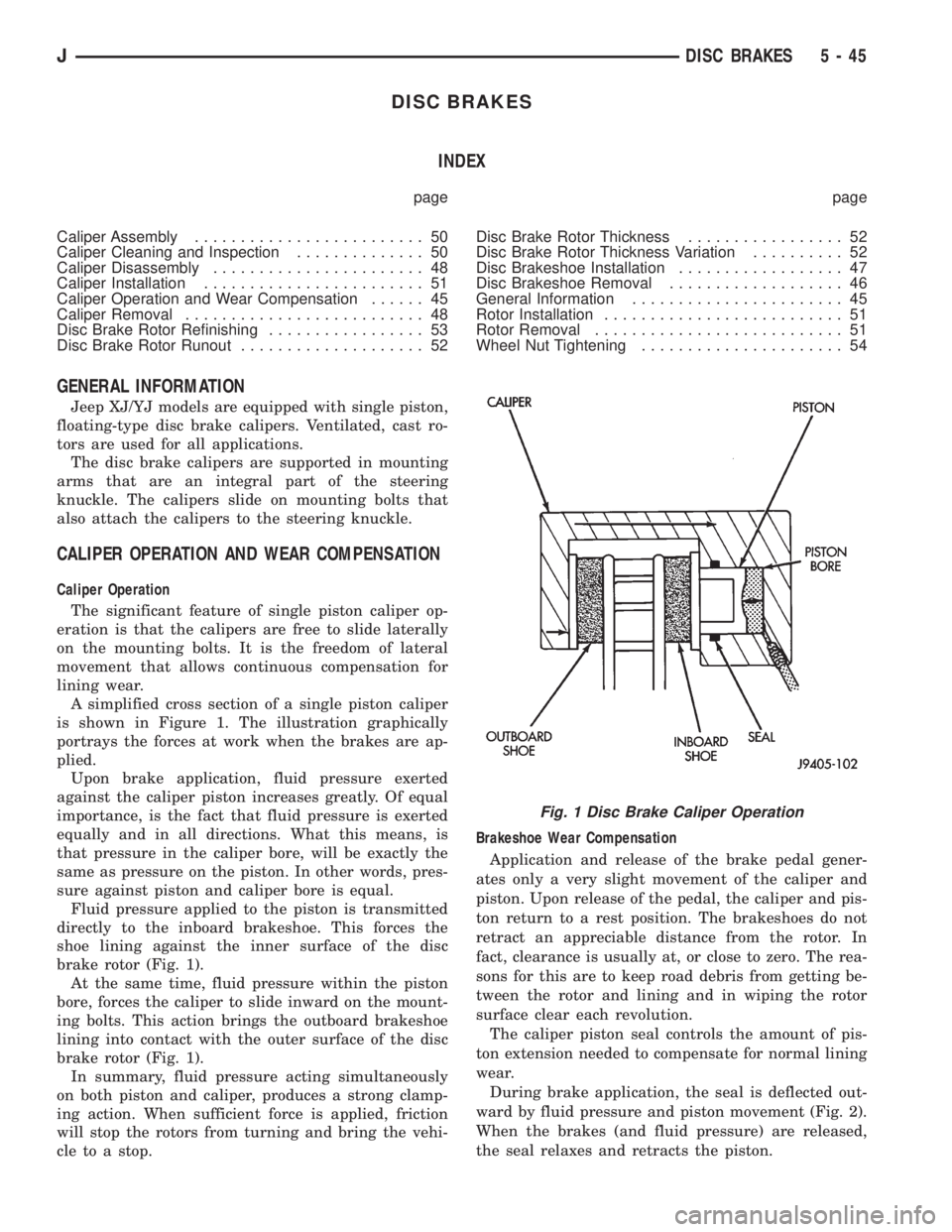
A simplified cross section of a single piston caliper
is shown in Figure 1. The illustration graphically
portrays the forces at work when the brakes are ap-
plied.
Upon brake application, fluid pressure exerted
against the caliper piston increases greatly. Of equal
importance, is the fact that fluid pressure is exerted
equally and in all directions. What this means, is
that pressure in the caliper bore, will be exactly the
same as pressure on the piston. In other words, pres-
sure against piston and caliper bore is equal.
Fluid pressure applied to the piston is transmitted
directly to the inboard brakeshoe. This forces the
shoe lining against the inner surface of the disc
brake rotor (Fig. 1).
At the same time, fluid pressure within the piston
bore, forces the caliper to slide inward on the mount-
ing bolts. This action brings the outboard brakeshoe
lining into contact with the outer surface of the disc
brake rotor (Fig. 1).
In summary, fluid pressure acting simultaneously
on both piston and caliper, produces a strong clamp-
ing action. When sufficient force is applied, friction
will stop the rotors from turning and bring the vehi-
cle to a stop.Brakeshoe Wear Compensation
Application and release of the brake pedal gener-
ates only a very slight movement of the caliper and
piston. Upon release of the pedal, the caliper and pis-
ton return to a rest position. The brakeshoes do not
retract an appreciable distance from the rotor. In
fact, clearance is usually at, or close to zero. The rea-
sons for this are to keep road debris from getting be-
tween the rotor and lining and in wiping the rotor
surface clear each revolution.
The caliper piston seal controls the amount of pis-
ton extension needed to compensate for normal lining
wear.
During brake application, the seal is deflected out-
ward by fluid pressure and piston movement (Fig. 2).
When the brakes (and fluid pressure) are released,
the seal relaxes and retracts the piston.
Fig. 1 Disc Brake Caliper Operation
JDISC BRAKES 5 - 45
Page 198 of 2158

The amount of piston retraction is determined by
brakelining wear. Generally, the amount is just
enough to maintain contact between the piston and
inboard brakeshoe. Brakelining running clearance at
the rotor, will be held between zero and a maximum
of 0.12 mm (0.005 in.).
DISC BRAKESHOE REMOVAL
(1) Raise vehicle and remove front wheels.
(2) Drain small amount of fluid from master cylin-
der front brake reservoir with suction gun.
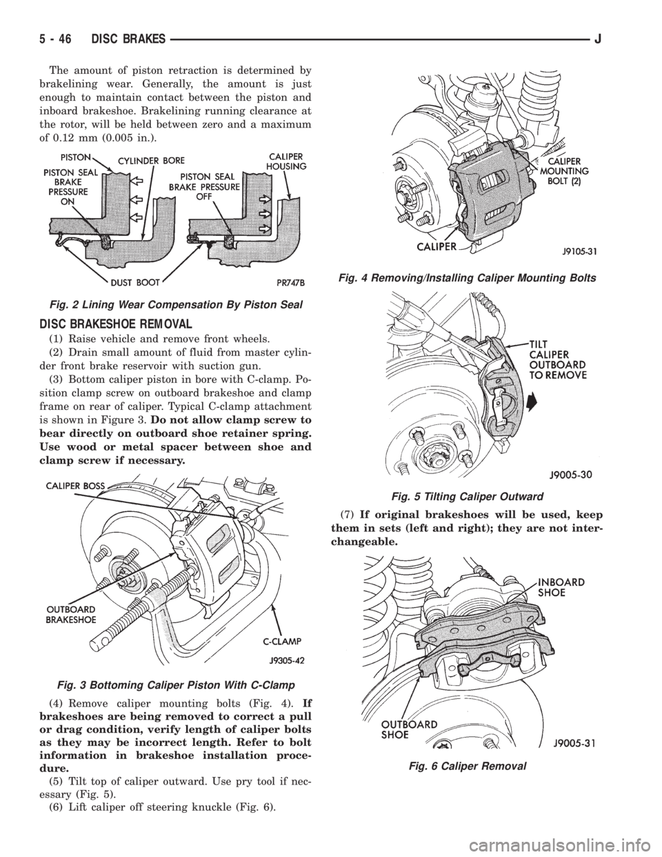
(3) Bottom caliper piston in bore with C-clamp. Po-
sition clamp screw on outboard brakeshoe and clamp
frame on rear of caliper. Typical C-clamp attachment
is shown in Figure 3.Do not allow clamp screw to
bear directly on outboard shoe retainer spring.
Use wood or metal spacer between shoe and
clamp screw if necessary.
(4) Remove caliper mounting bolts (Fig. 4).If
brakeshoes are being removed to correct a pull
or drag condition, verify length of caliper bolts
as they may be incorrect length. Refer to bolt
information in brakeshoe installation proce-
dure.
(5) Tilt top of caliper outward. Use pry tool if nec-
essary (Fig. 5).
(6) Lift caliper off steering knuckle (Fig. 6).(7)If original brakeshoes will be used, keep
them in sets (left and right); they are not inter-
changeable.
Fig. 2 Lining Wear Compensation By Piston Seal
Fig. 3 Bottoming Caliper Piston With C-Clamp
Fig. 4 Removing/Installing Caliper Mounting Bolts
Fig. 5 Tilting Caliper Outward
Fig. 6 Caliper Removal
5 - 46 DISC BRAKESJ
Page 200 of 2158

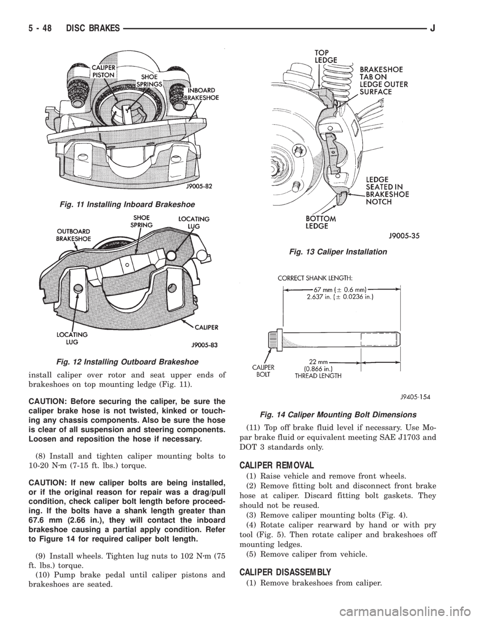
install caliper over rotor and seat upper ends of
brakeshoes on top mounting ledge (Fig. 11).
CAUTION: Before securing the caliper, be sure the
caliper brake hose is not twisted, kinked or touch-
ing any chassis components. Also be sure the hose
is clear of all suspension and steering components.
Loosen and reposition the hose if necessary.
(8) Install and tighten caliper mounting bolts to
10-20 Nzm (7-15 ft. lbs.) torque.
CAUTION: If new caliper bolts are being installed,
or if the original reason for repair was a drag/pull
condition, check caliper bolt length before proceed-
ing. If the bolts have a shank length greater than
67.6 mm (2.66 in.), they will contact the inboard
brakeshoe causing a partial apply condition. Refer
to Figure 14 for required caliper bolt length.
(9) Install wheels. Tighten lug nuts to 102 Nzm (75
ft. lbs.) torque.
(10) Pump brake pedal until caliper pistons and
brakeshoes are seated.(11) Top off brake fluid level if necessary. Use Mo-
par brake fluid or equivalent meeting SAE J1703 and
DOT 3 standards only.
CALIPER REMOVAL
(1) Raise vehicle and remove front wheels.
(2) Remove fitting bolt and disconnect front brake
hose at caliper. Discard fitting bolt gaskets. They
should not be reused.
(3) Remove caliper mounting bolts (Fig. 4).
(4) Rotate caliper rearward by hand or with pry
tool (Fig. 5). Then rotate caliper and brakeshoes off
mounting ledges.
(5) Remove caliper from vehicle.
CALIPER DISASSEMBLY
(1) Remove brakeshoes from caliper.
Fig. 11 Installing Inboard Brakeshoe
Fig. 12 Installing Outboard Brakeshoe
Fig. 13 Caliper Installation
Fig. 14 Caliper Mounting Bolt Dimensions
5 - 48 DISC BRAKESJ
Page 203 of 2158

CALIPER INSTALLATION
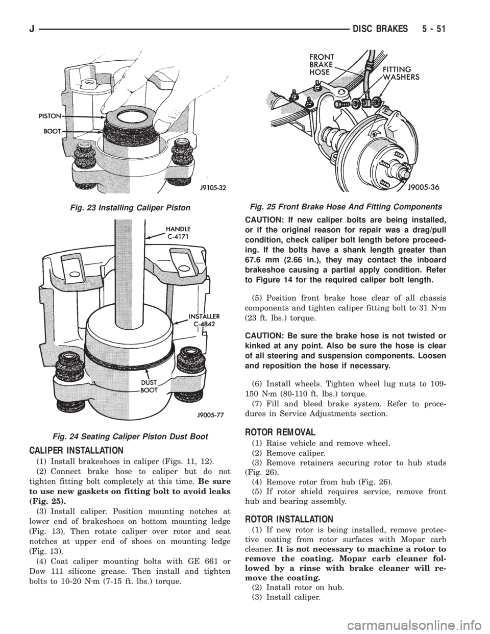
(1) Install brakeshoes in caliper (Figs. 11, 12).
(2) Connect brake hose to caliper but do not
tighten fitting bolt completely at this time.Be sure
to use new gaskets on fitting bolt to avoid leaks
(Fig. 25).
(3) Install caliper. Position mounting notches at
lower end of brakeshoes on bottom mounting ledge
(Fig. 13). Then rotate caliper over rotor and seat
notches at upper end of shoes on mounting ledge
(Fig. 13).
(4) Coat caliper mounting bolts with GE 661 or
Dow 111 silicone grease. Then install and tighten
bolts to 10-20 Nzm (7-15 ft. lbs.) torque.CAUTION: If new caliper bolts are being installed,
or if the original reason for repair was a drag/pull
condition, check caliper bolt length before proceed-
ing. If the bolts have a shank length greater than
67.6 mm (2.66 in.), they may contact the inboard
brakeshoe causing a partial apply condition. Refer
to Figure 14 for the required caliper bolt length.
(5) Position front brake hose clear of all chassis
components and tighten caliper fitting bolt to 31 Nzm
(23 ft. lbs.) torque.
CAUTION: Be sure the brake hose is not twisted or
kinked at any point. Also be sure the hose is clear
of all steering and suspension components. Loosen
and reposition the hose if necessary.
(6) Install wheels. Tighten wheel lug nuts to 109-
150 Nzm (80-110 ft. lbs.) torque.
(7) Fill and bleed brake system. Refer to proce-
dures in Service Adjustments section.
ROTOR REMOVAL
(1) Raise vehicle and remove wheel.
(2) Remove caliper.
(3) Remove retainers securing rotor to hub studs
(Fig. 26).
(4) Remove rotor from hub (Fig. 26).
(5) If rotor shield requires service, remove front
hub and bearing assembly.
ROTOR INSTALLATION
(1) If new rotor is being installed, remove protec-
tive coating from rotor surfaces with Mopar carb
cleaner.It is not necessary to machine a rotor to
remove the coating. Mopar carb cleaner fol-
lowed by a rinse with brake cleaner will re-
move the coating.
(2) Install rotor on hub.
(3) Install caliper.
Fig. 23 Installing Caliper Piston
Fig. 24 Seating Caliper Piston Dust Boot
Fig. 25 Front Brake Hose And Fitting Components
JDISC BRAKES 5 - 51