1995 JEEP XJ Brake warning lamp
[x] Cancel search: Brake warning lampPage 877 of 2158

ANTI-LOCK BRAKES
INDEX
page page
ABS Power Relay.......................... 1
ABS Pump Motor Relay..................... 1
ABS Warning Lamp........................ 2
Acceleration Switch......................... 1
Brake Pedal Travel Sensor................... 2
Brake Switch Input......................... 2Data Link Connector........................ 2
Diagram Index............................ 3
General Information........................ 1
Hydraulic Control Unit....................... 2
Pump Motor Speed Sensor................... 2
Wheel Speed Sensors...................... 1
GENERAL INFORMATION
Three fuses supply power for the Anti-Lock Brake
System (ABS); fuses 6 and 10 in the Power Distribu-
tion Center (PDC) and fuse 2 in the fuse block. Fuses
6 and 10 in the PDC are connected directly to battery
voltage and are HOT all times. Fuse 2 in the fuse
block is HOT when the ignition switch is the RUN
Position.
In the RUN position, the ignition switch connects
circuit A1 from fuse 6 in the PDC with circuit A38.
Circuit A38 connects to a bus bar in the fuse block.
The bus bar feeds circuit B236 through fuse 2. Fuse
2 is a 2 amp fuse.
Circuit B236 connects to the coil side of the ABS
power relay and cavity 53 of the ABS control module.
Circuit Z1 provides ground for the ABS control
module. Circuit Z1 connects to cavities 1 and 19 of
the ABS control module.
Refer to group 5, Brakes for operational descrip-
tions of ABS system components.
WHEEL SPEED SENSORS
The all wheel anti-lock system uses four wheel
speed sensors; one for each wheel. Each sensor con-
verts wheel speed into an electrical signal that it
transmits to the ABS control module. A pair of
twisted wires connect to each sensor to provide sig-
nals to the ABS control module.
Circuits B6 and B7 provide signals to ABS control
module from the right front wheel speed sensor. Cir-
cuit B6 which provides the LOW signal connects to
cavity 29 of the ABS control module. Circuit B7 con-
nects to cavity 47 of the module and provides the
HIGH signal.
Circuits B8 and B9 provide signals to ABS control
module from the left front wheel speed sensor. Cir-
cuit B8, which provides the LOW signal, connects to
cavity 30 of the ABS control module. Circuit B9 con-
nects to cavity 48 of the module and provides the
HIGH signal.
Circuits B1 and B2 provide signals to ABS control
module from the right rear wheel speed sensor. Cir-
cuit B1 which provides the LOW signal connects tocavity 45 of the ABS control module. Circuit B2 con-
nects to cavity 27 of the module and provides the
HIGH signal.
Circuits B4 and B3 provide signals to ABS control
module from the left rear wheel speed sensor. Circuit
B3, which provides the LOW signal, connects to cav-
ity 28 of the ABS control module. Circuit B4 connects
to cavity 46 of the module and provides the HIGH
signal.
ACCELERATION SWITCH
During four-wheel drive operation, the acceleration
switch provides deceleration data to the ABS control
module. Refer to Group 5, Brakes for additional in-
formation.
Circuits B515, B516, and B517 connect the acceler-
ation sensor to the ABS control module. Circuits
B515 and B516 provide switch states while circuit
B517 provides ground. At the ABS control module cir-
cuit B515 connects to cavity 25, circuit B516 connects
to cavity 43 and circuit B517 connects to cavity 26.
ABS POWER RELAY
The ABS power relay is located in the power distri-
bution center (PDC). When the ABS module grounds
the ABS power relay on circuit B207, the relay
switches to connect circuit A20 from PDC fuse 10 to
circuit B235. Circuit B236 from fuse 7 in the fuse
block splices to feed the coil side of the ABS power
relay. Circuit B207 connects to cavity 34 of the ABS
control module.
Circuit B235 is double crimped at the ABS power
relay. One branch of circuit B235 supplies power to
the coil side of the ABS pump motor relay. The other
branch of circuit B235 splices to cavities 3 and 33 of
the ABS control module and to the hydraulic control
unit.
ABS PUMP MOTOR RELAY
The ABS pump motor relay in the power distribu-
tion center (PDC) supplies voltage to the ABS pump
motor. When the ABS power relay energizes, circuit
B235 supplies battery voltage to the coil side of the
J8W-32 ANTI-LOCK BRAKESÐXJ-RHD 8W - 32 - 1
Page 878 of 2158

ABS pump motor relay. The ABS control module pro-
vides ground for the relay on circuit B116. Circuit
B116 connects to cavity 15 of the ABS control mod-
ule.
When the ABS pump motor energizes, it connects
circuit A10 from PDC fuse 8 to circuit B233. Circuit
B233 supplies battery voltage to the pump motor.
Circuit Z12 provides ground for the pump motor.
PUMP MOTOR SPEED SENSOR
The input from the pump motor speed sensor tells
the ABS control module that the pump is operating.
Circuits B219 and B220 from the control module con-
nect to the speed sensor.
BRAKE SWITCH INPUT
Circuit L50 from the stop lamp provides the brake
switch input to the ABS control module. When the
brake pedal is depressed, the stop lamp switch closes
to supply battery voltage from circuit L9 to circuit
L50. Circuit L50 connects to cavity 32 of the ABS
control module. Circuit L9 originates at fuse 4 in the
Power Distribution Center (PDC).
HYDRAULIC CONTROL UNIT
When the ABS power relay energizes, two branches
of circuit B235 splice to supply voltage to the isola-
tion and decay solenoids in the hydraulic control
unit. The hydraulic control unit contains three sepa-
rate isolation solenoids and three separate dump so-
lenoids. The ABS control module activates the decay
and isolation solenoids by providing separate ground
paths for each.
The ABS module provides a ground path for the
rear isolation solenoid on circuit B251. Circuit B251
connects to cavity 54 of the ABS control module.
For the right front isolation solenoid, the ABS mod-
ule provides a ground path on circuit B249. Circuit
B249 connects to cavity 38 of the ABS control mod-
ule.
On circuit B245, the ABS control module provides
ground for the left front isolation solenoid. Circuit
B245 connects to cavity 20 of the ABS control mod-
ule.
The ABS control module provides a ground path for
the rear dump solenoid on circuit B254. Circuit B254
connects to cavity 36 of the ABS control module.For the right front dump solenoid, the ABS module
provides a ground path on circuit B248. Circuit B248
connects to cavity 21 of the ABS control module.
On circuit B243, the ABS module provides ground
for the left dump solenoid. Circuit B243 connects to
cavity 2 of the ABS control module.
ABS WARNING LAMP
Circuit F87 provides power for the ABS warning
lamp at the instrument cluster. Ground for the ABS
warning lamp is provided by either the ABS control
module or by the ABS power relay when the relay is
not energized. The ABS control module illuminates
the lamp by providing ground on circuit B205.
Circuit B205 splices to connect to circuit B235
through a diode. When the ABS power relay is not
energized, it connects circuit B235 to circuit Z12. The
ground path for the warning lamp is through the di-
ode to circuit B235, through the ABS power relay to
ground on circuit Z12.
The diode between circuit B205 and B235 prevents
voltage from flowing to the ABS control module when
the ABS power relay switches to supply power on cir-
cuit B235.
DATA LINK CONNECTOR
Circuit D1 from cavity 23 of the ABS control mod-
ule receives data from the DRB scan tool through the
data link connector. The ABS control module trans-
mits data to the scan tool through the connector on
circuit D2. Circuit D2 originates at cavity 42 of the
ABS control module.
Through the data link connector, circuit Z12 pro-
vides ground for the DRB scan tool. Circuit Z12 ter-
minates at the right rear of the engine.
Circuit A4 from fuse 7 in the Power Distribution
Center (PDC) supplies power to fuse 13 in the PDC.
Fuse 13 powers circuit F39 which supplies battery
voltage to the scan tool through the diagnostic con-
nector.
HELPFUL INFORMATION
²Check fuses 7 and 13 in the PDC.
²If the vehicle is equipped with an automatic trans-
mission, circuits D1 and D2 are double crimped at
the data link connector and connect to the Power-
train Control Module (PCM).
8W - 32 - 2 8W-32 ANTI-LOCK BRAKESÐXJ-RHDJ
Page 890 of 2158
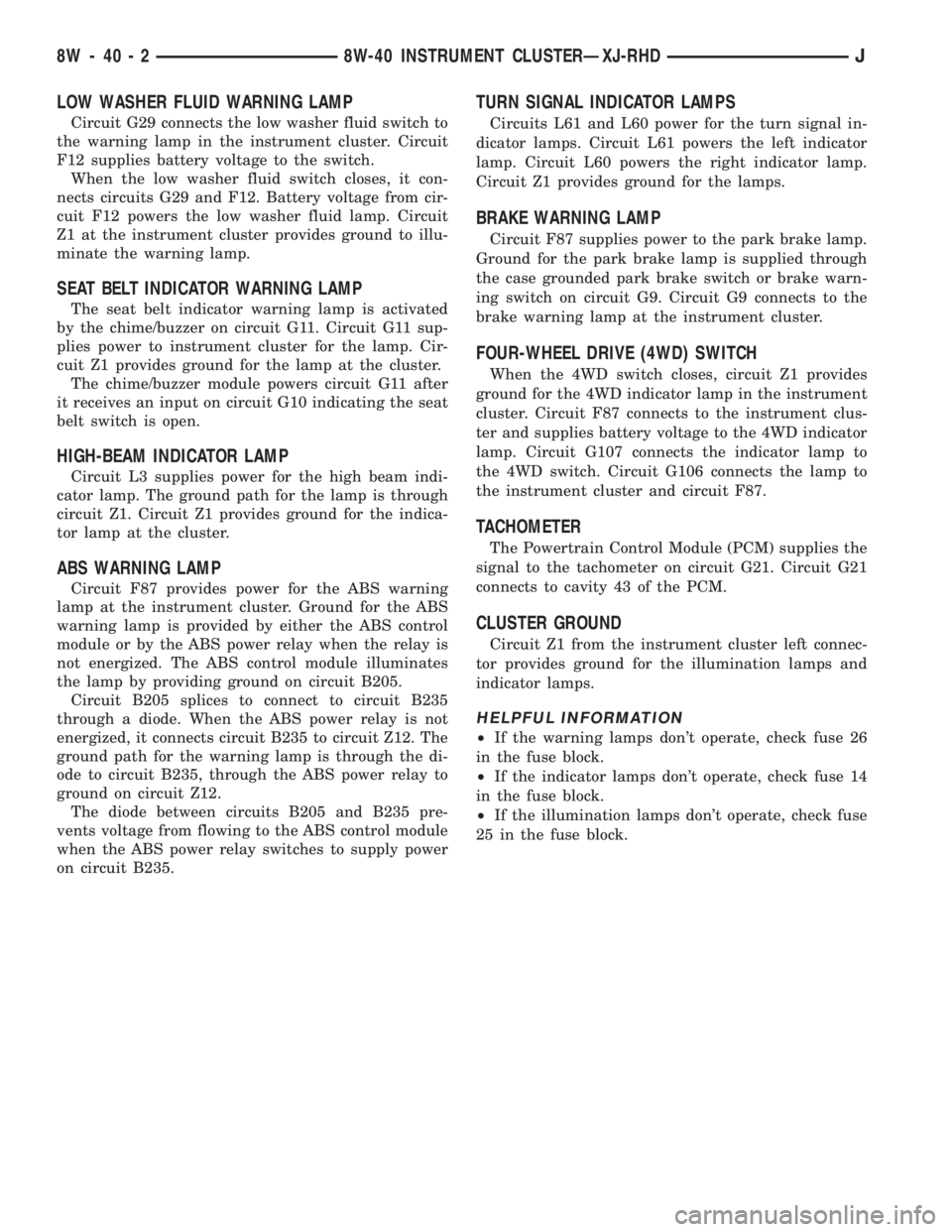
LOW WASHER FLUID WARNING LAMP
Circuit G29 connects the low washer fluid switch to
the warning lamp in the instrument cluster. Circuit
F12 supplies battery voltage to the switch.
When the low washer fluid switch closes, it con-
nects circuits G29 and F12. Battery voltage from cir-
cuit F12 powers the low washer fluid lamp. Circuit
Z1 at the instrument cluster provides ground to illu-
minate the warning lamp.
SEAT BELT INDICATOR WARNING LAMP
The seat belt indicator warning lamp is activated
by the chime/buzzer on circuit G11. Circuit G11 sup-
plies power to instrument cluster for the lamp. Cir-
cuit Z1 provides ground for the lamp at the cluster.
The chime/buzzer module powers circuit G11 after
it receives an input on circuit G10 indicating the seat
belt switch is open.
HIGH-BEAM INDICATOR LAMP
Circuit L3 supplies power for the high beam indi-
cator lamp. The ground path for the lamp is through
circuit Z1. Circuit Z1 provides ground for the indica-
tor lamp at the cluster.
ABS WARNING LAMP
Circuit F87 provides power for the ABS warning
lamp at the instrument cluster. Ground for the ABS
warning lamp is provided by either the ABS control
module or by the ABS power relay when the relay is
not energized. The ABS control module illuminates
the lamp by providing ground on circuit B205.
Circuit B205 splices to connect to circuit B235
through a diode. When the ABS power relay is not
energized, it connects circuit B235 to circuit Z12. The
ground path for the warning lamp is through the di-
ode to circuit B235, through the ABS power relay to
ground on circuit Z12.
The diode between circuits B205 and B235 pre-
vents voltage from flowing to the ABS control module
when the ABS power relay switches to supply power
on circuit B235.
TURN SIGNAL INDICATOR LAMPS
Circuits L61 and L60 power for the turn signal in-
dicator lamps. Circuit L61 powers the left indicator
lamp. Circuit L60 powers the right indicator lamp.
Circuit Z1 provides ground for the lamps.
BRAKE WARNING LAMP
Circuit F87 supplies power to the park brake lamp.
Ground for the park brake lamp is supplied through
the case grounded park brake switch or brake warn-
ing switch on circuit G9. Circuit G9 connects to the
brake warning lamp at the instrument cluster.
FOUR-WHEEL DRIVE (4WD) SWITCH
When the 4WD switch closes, circuit Z1 provides
ground for the 4WD indicator lamp in the instrument
cluster. Circuit F87 connects to the instrument clus-
ter and supplies battery voltage to the 4WD indicator
lamp. Circuit G107 connects the indicator lamp to
the 4WD switch. Circuit G106 connects the lamp to
the instrument cluster and circuit F87.
TACHOMETER
The Powertrain Control Module (PCM) supplies the
signal to the tachometer on circuit G21. Circuit G21
connects to cavity 43 of the PCM.
CLUSTER GROUND
Circuit Z1 from the instrument cluster left connec-
tor provides ground for the illumination lamps and
indicator lamps.
HELPFUL INFORMATION
²If the warning lamps don't operate, check fuse 26
in the fuse block.
²If the indicator lamps don't operate, check fuse 14
in the fuse block.
²If the illumination lamps don't operate, check fuse
25 in the fuse block.
8W - 40 - 2 8W-40 INSTRUMENT CLUSTERÐXJ-RHDJ
Page 891 of 2158
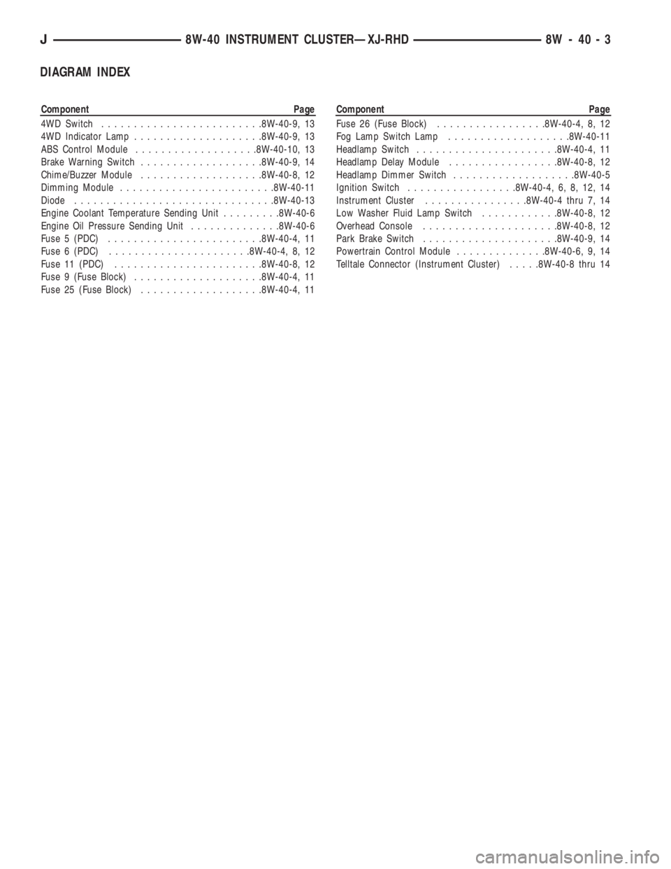
DIAGRAM INDEX
Component Page
4WD Switch.........................8W-40-9, 13
4WD Indicator Lamp....................8W-40-9, 13
ABS Control Module...................8W-40-10, 13
Brake Warning Switch...................8W-40-9, 14
Chime/Buzzer Module...................8W-40-8, 12
Dimming Module........................8W-40-11
Diode...............................8W-40-13
Engine Coolant Temperature Sending Unit.........8W-40-6
Engine Oil Pressure Sending Unit..............8W-40-6
Fuse 5 (PDC)........................8W-40-4, 11
Fuse 6 (PDC)......................8W-40-4, 8, 12
Fuse 11 (PDC).......................8W-40-8, 12
Fuse 9 (Fuse Block)....................8W-40-4, 11
Fuse 25 (Fuse Block)...................8W-40-4, 11Component Page
Fuse 26 (Fuse Block).................8W-40-4, 8, 12
Fog Lamp Switch Lamp...................8W-40-11
Headlamp Switch......................8W-40-4, 11
Headlamp Delay Module.................8W-40-8, 12
Headlamp Dimmer Switch...................8W-40-5
Ignition Switch.................8W-40-4, 6, 8, 12, 14
Instrument Cluster................8W-40-4 thru 7, 14
Low Washer Fluid Lamp Switch............8W-40-8, 12
Overhead Console.....................8W-40-8, 12
Park Brake Switch.....................8W-40-9, 14
Powertrain Control Module..............8W-40-6, 9, 14
Telltale Connector (Instrument Cluster).....8W-40-8 thru 14
J8W-40 INSTRUMENT CLUSTERÐXJ-RHD 8W - 40 - 3
Page 1085 of 2158
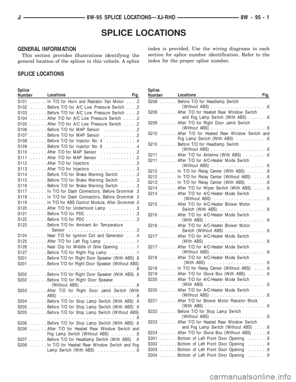
SPLICE LOCATIONS
GENERAL INFORMATION
This section provides illustrations identifying the
general location of the splices in this vehicle. A spliceindex is provided. Use the wiring diagrams in each
section for splice number identification. Refer to the
index for the proper splice number.
SPLICE LOCATIONS
Splice
NumberLocations Fig.
S101......InT/OforHorn and Radiator Fan Motor....2
S102......Before T/O for A/C Low Pressure Switch....2
S103......Before T/O for A/C Low Pressure Switch....2
S104......After T/O for A/C Low Pressure Switch.....2
S105......After T/O for A/C Low Pressure Switch.....2
S106......Before T/O for MAP Sensor............2
S107......Before T/O for MAP Sensor............2
S108......Before T/O for Injector No. 4...........4
S109......Before T/O for Injector No. 6...........4
S110......After T/O for MAP Sensor.............2
S111......After T/O for MAP Sensor.............2
S112......After T/O for Injectors................3
S113......After T/O for Injectors................3
S114......Before T/O for Brake Warning Switch......3
S115......Before T/O for Brake Warning Switch......3
S116......Before T/O for Brake Warning Switch......3
S117......InT/OforDash Connectors, Before Grommet .3
S118......InT/OforDash Connectors, Before Grommet .3
S119......InT/OforABSControl Module, After Grommet .5
S120......After T/O for Underhood Lamp..........3
S121......Before T/O for PDC..................3
S122......Before T/O for PDC..................3
S123......Before T/O for Ambient Air Temperature
Sensor........................3
S124......Near T/O for Ignition Coil and Generator....4
S125......After T/O for Left Fog Lamp............1
S126......Near Clip for Middle of Gille Opening......1
S127......Before T/O for Right Fog Lamp..........1
S201......Before T/O for Right Door Speaker (With ABS) .6
S201......Before T/O for Right Door Speaker (Without ABS)
...............................6
S202......Before T/O for Right Door Speaker (With ABS) .6
S202......Before T/O for Right Door Speaker
(Without ABS)....................6
S203......After T/O for Right Door Jamb Switch (With
ABS)...........................6
S204......Before T/O for Stop Lamp Switch (With ABS) .6
S205......Before T/O for Stop Lamp Switch (With ABS) .6
S205......Before T/O for Stop Lamp Switch (Without ABS)
...............................6
S206......Before T/O for Stop Lamp Switch (With ABS) .6
S206......After T/O for Heated Rear Window Switch and
Fog Lamp Switch (Without ABS).........6
S207......Before T/O for Headlamp Switch (With ABS) .6
S208......InT/OforHeated Rear Window Switch and Fog
Lamp Switch (With ABS)..............6Splice
NumberLocations Fig.
S208......Before T/O for Headlamp Switch
(Without ABS)....................6
S209......After T/O for Heated Rear Window Switch
and Fog Lamp Switch (With ABS).......6
S209......After T/O for Right Door Jamb Switch
(Without ABS)....................6
S210......After T/O for Heated Rear Window Switch and
Fog Lamp Switch (With ABS)...........6
S210......Before T/O for Headlamp Switch
(Without ABS)....................6
S211......After T/O for Antenna (With ABS)........6
S211......After T/O for A/C-Heater Mode Switch
(Without ABS)....................6
S212......InT/OforRelay Center (With ABS).......6
S212......InT/OforRelay Center (Without ABS).....6
S213......InT/OforRelay Center (With ABS).......6
S214......After T/O for Wiper Switch (With ABS).....6
S214......After T/O for A/C-Heater Mode Switch
(Without ABS)...................6
S215......After T/O for A/C-Heater Blower Motor
Switch (With ABS).................6
S216......After T/O for A/C-Heater Mode Switch
(With ABS)......................6
S216......After T/O for A/C-Heater Blower Motor
Switch (Without ABS)...............6
S217......After T/O for A/C-Heater Mode Switch
(With ABS)......................6
S217......After T/O for A/C-Heater Mode Switch
(Without ABS)....................6
S218......After T/O for A/C-Heater Mode Switch
(With ABS).....................6
S218......InT/OforRelay Center (Without ABS).....6
S219......After T/O for Glove Box (With ABS).......6
S220......After T/O for A/C-Heater Mode Switch
(With ABS)......................6
S220......After T/O for A/C-Heater Mode Switch
(Without ABS)....................6
S221......After T/O for Blower Motor Resistor Block
(With ABS)......................6
S222......Before T/O for Stop Lamp Switch
(Without ABS)....................6
S223......After T/O for Heated Rear Window Switch
and Fog Lamp Switch (Without ABS).....6
S224......After T/O for Glove Box (Without ABS).....6
S301......Bottom of Left Front Door Opening.......9
S302......Bottom of Left Front Door Opening.......9
S303......Bottom of Left Front Door Opening.......9
S304......Bottom of Left Front Door Opening.......9
J8W-95 SPLICE LOCATIONSÐXJ-RHD 8W - 95 - 1
Page 1094 of 2158
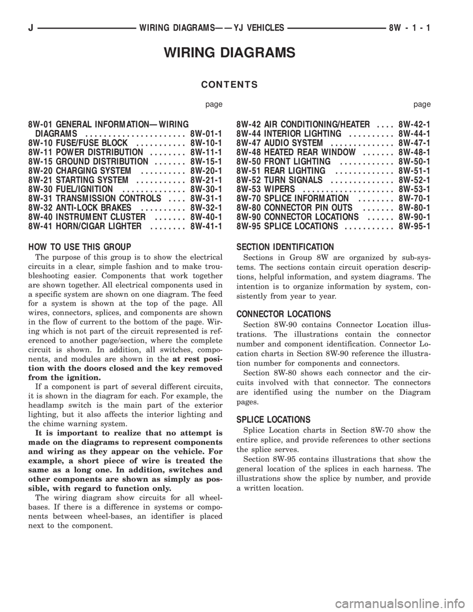
WIRING DIAGRAMS
CONTENTS
page page
8W-01 GENERAL INFORMATIONÐWIRING
DIAGRAMS...................... 8W-01-1
8W-10 FUSE/FUSE BLOCK........... 8W-10-1
8W-11 POWER DISTRIBUTION........ 8W-11-1
8W-15 GROUND DISTRIBUTION....... 8W-15-1
8W-20 CHARGING SYSTEM.......... 8W-20-1
8W-21 STARTING SYSTEM........... 8W-21-1
8W-30 FUEL/IGNITION.............. 8W-30-1
8W-31 TRANSMISSION CONTROLS.... 8W-31-1
8W-32 ANTI-LOCK BRAKES.......... 8W-32-1
8W-40 INSTRUMENT CLUSTER....... 8W-40-1
8W-41 HORN/CIGAR LIGHTER........ 8W-41-18W-42 AIR CONDITIONING/HEATER.... 8W-42-1
8W-44 INTERIOR LIGHTING.......... 8W-44-1
8W-47 AUDIO SYSTEM.............. 8W-47-1
8W-48 HEATED REAR WINDOW....... 8W-48-1
8W-50 FRONT LIGHTING............ 8W-50-1
8W-51 REAR LIGHTING............. 8W-51-1
8W-52 TURN SIGNALS.............. 8W-52-1
8W-53 WIPERS.................... 8W-53-1
8W-70 SPLICE INFORMATION........ 8W-70-1
8W-80 CONNECTOR PIN OUTS....... 8W-80-1
8W-90 CONNECTOR LOCATIONS...... 8W-90-1
8W-95 SPLICE LOCATIONS........... 8W-95-1
HOW TO USE THIS GROUP
The purpose of this group is to show the electrical
circuits in a clear, simple fashion and to make trou-
bleshooting easier. Components that work together
are shown together. All electrical components used in
a specific system are shown on one diagram. The feed
for a system is shown at the top of the page. All
wires, connectors, splices, and components are shown
in the flow of current to the bottom of the page. Wir-
ing which is not part of the circuit represented is ref-
erenced to another page/section, where the complete
circuit is shown. In addition, all switches, compo-
nents, and modules are shown in theat rest posi-
tion with the doors closed and the key removed
from the ignition.
If a component is part of several different circuits,
it is shown in the diagram for each. For example, the
headlamp switch is the main part of the exterior
lighting, but it also affects the interior lighting and
the chime warning system.
It is important to realize that no attempt is
made on the diagrams to represent components
and wiring as they appear on the vehicle. For
example, a short piece of wire is treated the
same as a long one. In addition, switches and
other components are shown as simply as pos-
sible, with regard to function only.
The wiring diagram show circuits for all wheel-
bases. If there is a difference in systems or compo-
nents between wheel-bases, an identifier is placed
next to the component.
SECTION IDENTIFICATION
Sections in Group 8W are organized by sub-sys-
tems. The sections contain circuit operation descrip-
tions, helpful information, and system diagrams. The
intention is to organize information by system, con-
sistently from year to year.
CONNECTOR LOCATIONS
Section 8W-90 contains Connector Location illus-
trations. The illustrations contain the connector
number and component identification. Connector Lo-
cation charts in Section 8W-90 reference the illustra-
tion number for components and connectors.
Section 8W-80 shows each connector and the cir-
cuits involved with that connector. The connectors
are identified using the number on the Diagram
pages.
SPLICE LOCATIONS
Splice Location charts in Section 8W-70 show the
entire splice, and provide references to other sections
the splice serves.
Section 8W-95 contains illustrations that show the
general location of the splices in each harness. The
illustrations show the splice by number, and provide
a written location.
JWIRING DIAGRAMSÐÐYJ VEHICLES 8W - 1 - 1
Page 1147 of 2158
module provides voltage to and receives input from.
Circuit B210 from cavity 41 of the ABS control mod-
ule provides voltage to the sensor. Circuit B258 car-
ries the signal from the sensor to cavity 16 of the
ABS module.
BRAKE SWITCH INPUT
Circuit L50 from the stop lamp provides the brake
switch input to the ABS control module. When the
brake pedal is pressed, the stop lamp switch closes to
supply battery voltage from circuit F32 to circuit
L50. Circuit L50 connects to cavity 32 of the ABS
control module. Circuit F32 originates at fuse 3 in
the fuse block.
Circuit A6 from Power Distribution Center (PDC)
fuse 3 supplies voltage to the fuse block for circuit
F32.
HYDRAULIC CONTROL UNIT
When the ABS power relay energizes, two branches
of circuit B15 splice to supply voltage to the isolation
and decay solenoids in the hydraulic control unit.
The hydraulic control unit contains three separate
isolation solenoids and three separate decay sole-
noids. The ABS control module activates the decay
and isolation solenoids by providing separate ground
paths for each.
The ABS module provides a ground path for the
rear isolation solenoid on circuit B251. Circuit B251
connects to cavity 54 of the ABS control module.
For the right front isolation solenoid, the ABS mod-
ule provides a ground path on circuit B249. Circuit
B249 connects to cavity 38 of the ABS control mod-
ule.
On circuit B245, the ABS module provides ground
for the left front isolation solenoid. Circuit B245 con-
nects to cavity 20 of the ABS control module.
The ABS module provides a ground path for the
rear decay solenoid on circuit B254. Circuit B254
connects to cavity 36 of the ABS control module.
For the right front decay solenoid, the ABS module
provides a ground path on circuit B248. Circuit B248
connects to cavity 21 of the ABS control module.
On circuit B243, the ABS module provides ground
for the left decay solenoid. Circuit B243 connects to
cavity 2 of the ABS control module.
ABS WARNING LAMP
Circuit G5 provides power for the ABS warning
lamp at the instrument cluster. Ground for the ABS
warning lamp is provided by either the ABS control
module or by the ABS power relay when the relay is
not energized. The ABS control module illuminates
the lamp by providing ground on circuit G19.
Circuit G19 splices to connect to circuit B15
through a diode. When the ABS power relay is notenergized, it connects circuit B15 to circuit Z12. The
ground path for the warning lamp is through the di-
ode to circuit B15, through the ABS power relay to
ground on circuit Z12.
The diode between circuit G19 and B15 prevents
voltage from flowing to the ABS control module when
the ABS power relay switches to supply power on cir-
cuit B15.
DATA LINK CONNECTOR
Circuit D11 from cavity 23 of the ABS control mod-
ule receives data from the DRB scan tool through the
data link connector. The ABS control module trans-
mits data to the scan tool through the connector on
circuit D12. Circuit D12 originates at cavity 42 of the
ABS control module.
Through the data link connector, circuit Z12 pro-
vides ground for the DRB scan tool. Circuit Z12 ter-
minates at the right rear of the dash panel.
Circuit A4 from fuse 8 in the Power Distribution
Center (PDC) supplies power to fuse 16 in the PDC.
Fuse 16 powers circuit M1 which supplies battery
voltage to the scan tool through the diagnostic con-
nector.
HELPFUL INFORMATION
²Check fuses 4, 9 and 10 in the PDC
²Check fuse 13 in the fuse block
DIAGRAM INDEX
Component Page
ABS Power Relay........................8W-32-4
ABS Pump Motor/Sensor...................8W-32-5
ABS Warning Lamp.......................8W-32-4
ABS Control Module..................8W-32-3 thru 7
ABS Pump Motor Relay....................8W-32-5
Brake Pedal Travel Sensor...................8W-32-6
Data Link Connector......................8W-32-6
Fuse 1 Fuse Block........................8W-32-4
Fuse 3 Fuse Block........................8W-32-6
Fuse 3 (PDC)...........................8W-32-6
Fuse 4 (PDC)...........................8W-32-4
Fuse 8 (PDC)...........................8W-32-6
Fuse 10 (PDC)..........................8W-32-4
Fuse 12 Fuse Block.......................8W-32-4
Fuse 12 (PDC)..........................8W-32-6
Fuse 13 (PDC)..........................8W-32-4
Hydraulic Actuation Unit....................8W-32-3
Ignition Switch..........................8W-32-4
Powertrain Control Module (PCM)..............8W-32-6
Stop Lamp Switch........................8W-32-6
Wheel Speed Sensors......................8W-32-7
8W - 32 - 2 8W-32 ANTI-LOCK BRAKESÐYJ VEHICLESJ
Page 1155 of 2158
MALFUNCTION INDICATOR (CHECK ENGINE)
LAMP
The Powertrain Control Module (PCM) provides
ground for the malfunction indicator (Check Engine)
lamp on circuit G3. Circuit G3 connects to cavity 32
of the PCM. Circuit G5 connects to the instrument
cluster and supplies battery voltage for the malfunc-
tion indicator lamp. When illuminated, the malfunc-
tion indicator lamp displays the message CHECK
ENGINE.
For information regarding diagnostic trouble code
access using the malfunction indicator lamp, refer to
Group 14, Fuel Systems.
UP-SHIFT LAMP
On vehicles equipped with a manual transmission,
the Powertrain Control Module (PCM) provides
ground for the Up-Shift lamp on circuit K54. Circuit
G5 provides battery voltage for the lamp.
ABS WARNING LAMP
Circuit G5 provides power for the ABS warning
lamp at the instrument cluster. Ground for the ABS
warning lamp is provided by either the ABS control
module or by the ABS power relay when the relay is
not energized. The ABS control module illuminates
the lamp by providing ground on circuit G19.
Circuit G19 splices to connect to circuit B15
through a diode. When the ABS power relay is not
energized, it connects circuit B15 to circuit Z12. The
ground path for the warning lamp is provided
through the diode to circuit B15, through the ABS
power relay to ground on circuit Z12.
The diode between circuit G19 and B15 prevents
voltage from flowing to the ABS control module when
the ABS power relay switches to supply power on cir-
cuit B15.
BRAKE WARNING LAMP
Circuit G5 provides battery voltage for the brake
warning lamp. Circuit G11 can provide ground for
the lamp in 3 ways. The first ground path is through
the ignition switch when the key is in the START po-
sition.
The second ground path for the brake warning
lamp on circuit G11 is through the case grounded
brake warning switch. When the switch closes it pro-
vides a ground.
The third ground path on circuit G11 is through
the case grounded park brake switch. When the
switch closes it provides ground.
HIGH BEAM INDICATOR LAMP
Circuit G34 supplies power for the high-beam indi-
cator lamp when the operator either flashes the opti-
cal horn (high beams) or selects high beam operation.
Circuit Z1 provides the ground path for the lamp.
Circuit L3 from the headlamp switch powers the
high beam circuits of the headlamps. On vehicles not
equipped with Daytime Running Lamps (DRL), cir-
cuit G34 double crimps to circuit L3 at the bulkhead
connector.
On vehicles equipped with DRL, circuit L3 splices
to the DRL module. The DRL module powers circuit
G34.
TURN SIGNAL INDICATOR LAMPS
Circuit L61 supplies battery voltage to the left turn
signal indicator lamp. The right turn signal indicator
lamp receives battery voltage from circuit L60. The
turn signal/hazard flasher switch powers circuits L60
and L61. Circuit Z1 provides ground for the lamps.
HELPFUL INFORMATION
²If the warning lamps, gauges and indicator lamps
don't operate, check fuse 4 in the PDC and fuse 9 in
the fuse block.
²If the illumination lamps don't operate, check fuse
10 in the fuse block.
DIAGRAM INDEX
Component Page
4WD Switch............................8W-40-9
ABS Control Module......................8W-40-5
Brake Warning Switch.....................8W-40-5
Combination Buzzer.....................8W-40-7, 8
Daytime Running Lamp (DRL) Module.........8W-40-4, 6
Engine Coolant Temperature Sensor...........8W-40-7, 8
Engine Oil Pressure Sensor..................8W-40-9
Fuse 3 (PDC).......................8W-40-3, 7, 8
Fuse 4 (PDC).......................8W-40-4, 7, 8
Fuse 7 (PDC)...........................8W-40-6
Fuse 8 (Fuse Block)...................8W-40-3, 7, 8
Fuse 9 (Fuse Block).......................8W-40-8
Fuse 10 (Fuse Block).................8W-40-3, 7, 10
Gauge Package......................8W-40-7, 8, 9
Headlamp Switch...................8W-40-3, 6, 7, 8
Headlamp Dimmer Switch...................8W-40-6
Ignition Switch......................8W-40-4, 5, 8
Instrument Cluster...................8W-40-3 thru 9
Panel Lamp Dimmer Switch..............8W-40-3, 7, 8
Park Brake Switch........................8W-40-5
Powertrain Control Module.................8W-40-4, 5
8W - 40 - 2 8W-40 INSTRUMENT CLUSTERÐYJ VEHICLESJ