1995 JEEP XJ headlamp
[x] Cancel search: headlampPage 390 of 2158
TURN SIGNAL INDICATOR LAMPS
(1) Disconnect battery negative cable. Remove left
instrument cluster bezel and main cluster assembly.
Probe cavity 20 of cluster connector. Check for conti-
nuity to a good ground. There should be continuity. If
OK, go to next step. If not OK, repair open circuit to
ground.
(2) Connect battery negative cable. Install a
jumper wire from cavity 18 (left indicator) or cavity 7
(right indicator) of cluster connector to a 12-volt bat-
tery feed. Lamp should light. If OK, continue to next
step. If not OK, replace bulb.
(3) Disconnect battery negative cable. Check for
continuity between cavity 18 (left indicator) or cavity
7 (right indicator) of cluster connector and cavity H
(left front turn signal) or cavity J (right front turn
signal) of steering column wiring connector. There
should be continuity. If OK, refer to Group 8J - Turn
Signal and Hazard Warning Systems for further di-
agnosis. If not OK, repair open circuit as required.
UPSHIFT INDICATOR LAMP
(1) Disconnect battery negative cable. Unplug PCM
connector. Connect battery negative cable. Turn igni-
tion switch to ON. Install a jumper wire from cavity
54 of PCM connector (Fig. 5) to a good ground. Lamp
should light. Remove jumper from ground. Lamp
should go off. If OK, refer to Powertrain Diagnostic
Procedures manual to diagnose PCM. If not OK, turn
ignition switch to OFF and go to next step.
(2) Disconnect battery negative cable. Remove left
instrument cluster bezel and main cluster assembly.
Install a jumper wire from cavity 5 of cluster connec-
tor to a good ground. Connect battery negative cable.
Turn ignition switch to ON. Lamp should light. If
OK, go to next step. If not OK, replace bulb.
(3) Turn ignition switch to OFF. Disconnect battery
negative cable. Unplug cluster connector. Check for
continuity between cavity 5 of cluster connector and
a good ground. There should be no continuity. If OK,
go to next step. If not OK, repair short circuit as re-
quired.(4) Check for continuity between cavity 5 of cluster
connector and cavity 54 of PCM connector. There
should be continuity. If not OK, repair open circuit as
required.
CLUSTER ILLUMINATION LAMPS
(1) Check fuse 10 in fuseblock module. If OK, go to
next step. If not OK, replace fuse.
(2) Turn park lamps on at headlamp switch. Rotate
panel dimmer switch thumb-wheel to HI position,
just before interior lamps detent. Check for battery
voltage at fuse 10 in fuseblock module. Rotate panel
dimmer thumb-wheel towards LO position while ob-
serving test voltmeter. Reading should go from bat-
tery voltage to zero volts. If OK, go to next step. If
not OK, repair open circuit to headlamp switch or re-
fer to Group 8L - Lamps to diagnose headlamp
switch.
(3) Disconnect battery negative cable. Remove left
or center instrument cluster bezel and main or gauge
package cluster assembly. Unplug cluster connector.
Connect battery negative cable. Turn park lamps on
at headlamp switch. Rotate panel dimmer thumb-
wheel to HI position, just before interior lamps de-
tent. Check for battery voltage at cavity 21 of main
cluster connector, or cavity 7 of gauge package clus-
ter connector. If OK, go to next step. If not OK, re-
pair open circuit to fuse as required.
(4) Turn park lamps off. Disconnect battery nega-
tive cable. Remove fuse 10 from fuseblock module.
Probe cavity 21 of main cluster connector, or cavity 7
of gauge package cluster connector. Check for conti-
nuity to a good ground. There should be no continu-
ity. If OK, go to next step. If not OK, repair short
circuit as required.
(5) Probe cavity 20 of main cluster connector, or
cavities 1 and 13 of gauge package cluster connector.
Check for continuity to ground. There should be con-
tinuity. If not OK, repair open circuit as required.
8E - 34 INSTRUMENT PANEL AND GAUGESÐYJJ
Page 398 of 2158
HEADLAMP OR PANEL DIMMER SWITCH
REMOVE/INSTALL
(1) Disconnect battery negative cable.
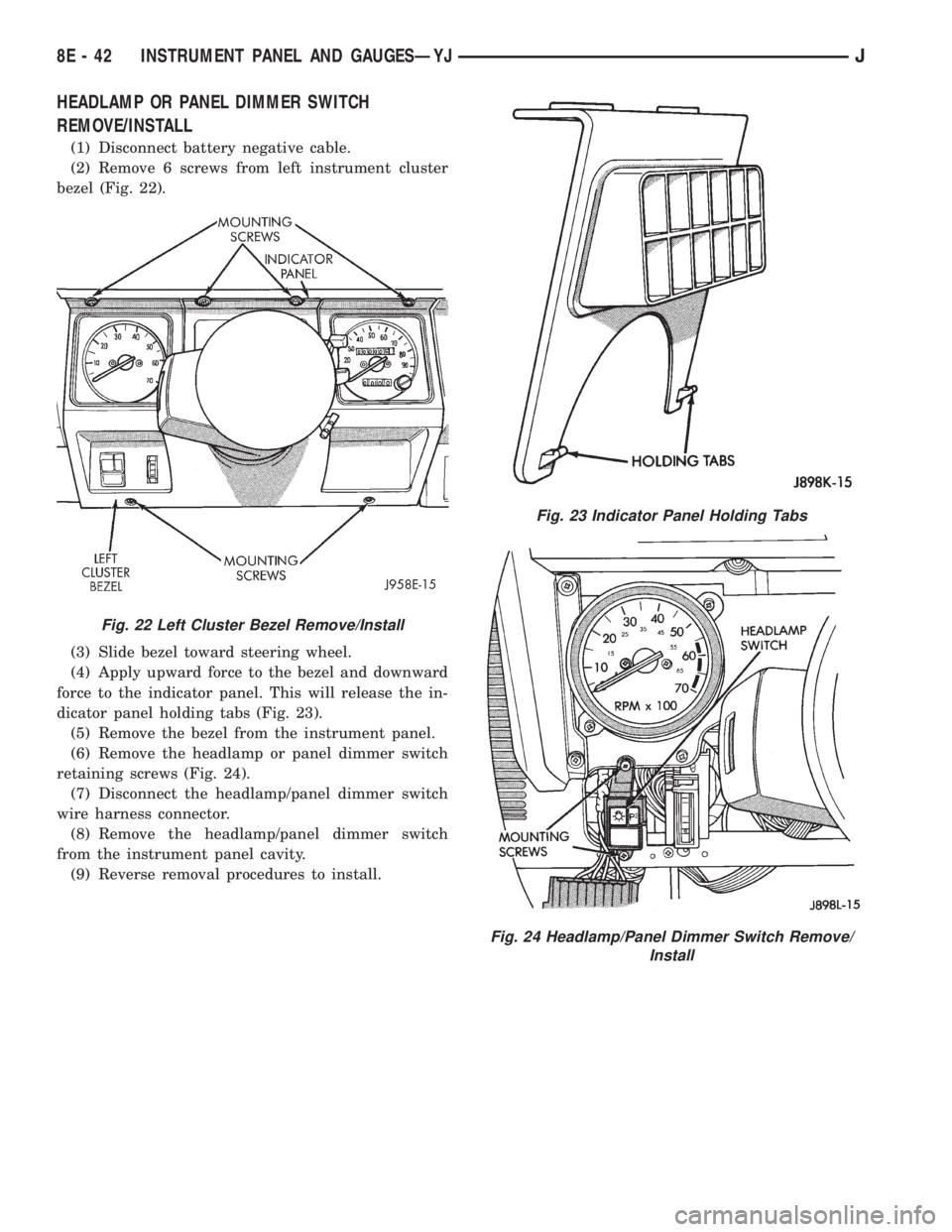
(2) Remove 6 screws from left instrument cluster
bezel (Fig. 22).
(3) Slide bezel toward steering wheel.
(4) Apply upward force to the bezel and downward
force to the indicator panel. This will release the in-
dicator panel holding tabs (Fig. 23).
(5) Remove the bezel from the instrument panel.
(6) Remove the headlamp or panel dimmer switch
retaining screws (Fig. 24).
(7) Disconnect the headlamp/panel dimmer switch
wire harness connector.
(8) Remove the headlamp/panel dimmer switch
from the instrument panel cavity.
(9) Reverse removal procedures to install.
Fig. 22 Left Cluster Bezel Remove/Install
Fig. 23 Indicator Panel Holding Tabs
Fig. 24 Headlamp/Panel Dimmer Switch Remove/
Install
8E - 42 INSTRUMENT PANEL AND GAUGESÐYJJ
Page 401 of 2158
AUDIO SYSTEMS
CONTENTS
page page
DIAGNOSIS............................. 2
GENERAL INFORMATION.................. 1SERVICE PROCEDURES................... 6
GENERAL INFORMATION
Following are general descriptions of major compo-
nents used in XJ (Cherokee)/YJ (Wrangler) audio sys-
tems. Refer to Group 8W - Wiring Diagrams for
complete circuit descriptions and diagrams.
RADIOS
Radio options for the XJ and YJ models include an
AM/FM stereo or an AM/FM stereo/cassette receiver.
Both units are Electronically-Tuned Radios (ETR)
and include a clock function. For more information
on radio features, setting procedures, and control
functions refer to the owner's manual.
IN-LINE FUSE
Each radio receives fused battery feed when the ig-
nition switch is in the ON or ACCESSORY position.
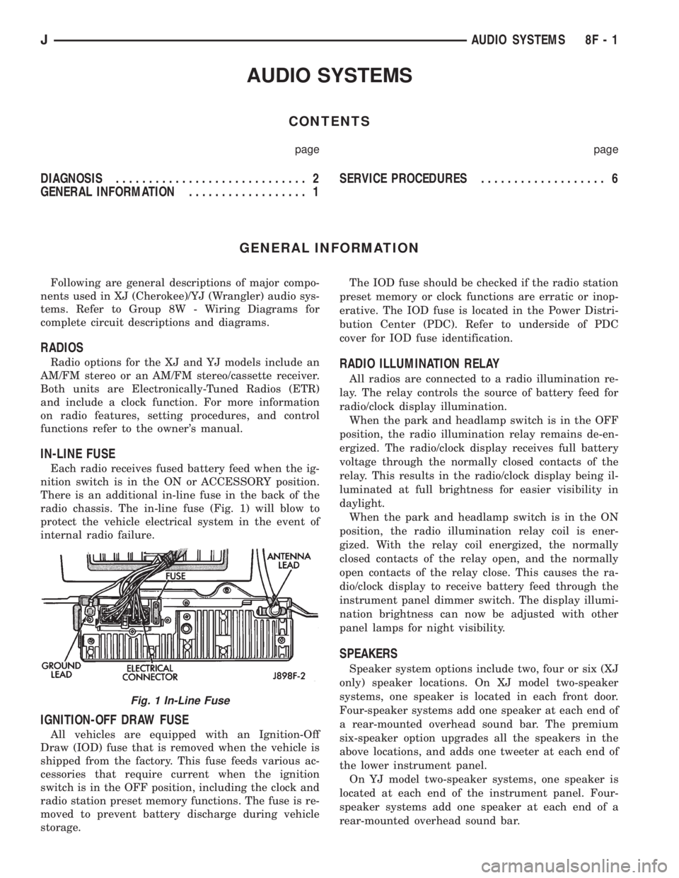
There is an additional in-line fuse in the back of the
radio chassis. The in-line fuse (Fig. 1) will blow to
protect the vehicle electrical system in the event of
internal radio failure.
IGNITION-OFF DRAW FUSE
All vehicles are equipped with an Ignition-Off
Draw (IOD) fuse that is removed when the vehicle is
shipped from the factory. This fuse feeds various ac-
cessories that require current when the ignition
switch is in the OFF position, including the clock and
radio station preset memory functions. The fuse is re-
moved to prevent battery discharge during vehicle
storage.The IOD fuse should be checked if the radio station
preset memory or clock functions are erratic or inop-
erative. The IOD fuse is located in the Power Distri-
bution Center (PDC). Refer to underside of PDC
cover for IOD fuse identification.
RADIO ILLUMINATION RELAY
All radios are connected to a radio illumination re-
lay. The relay controls the source of battery feed for
radio/clock display illumination.
When the park and headlamp switch is in the OFF
position, the radio illumination relay remains de-en-
ergized. The radio/clock display receives full battery
voltage through the normally closed contacts of the
relay. This results in the radio/clock display being il-
luminated at full brightness for easier visibility in
daylight.
When the park and headlamp switch is in the ON
position, the radio illumination relay coil is ener-
gized. With the relay coil energized, the normally
closed contacts of the relay open, and the normally
open contacts of the relay close. This causes the ra-
dio/clock display to receive battery feed through the
instrument panel dimmer switch. The display illumi-
nation brightness can now be adjusted with other
panel lamps for night visibility.
SPEAKERS
Speaker system options include two, four or six (XJ
only) speaker locations. On XJ model two-speaker
systems, one speaker is located in each front door.
Four-speaker systems add one speaker at each end of
a rear-mounted overhead sound bar. The premium
six-speaker option upgrades all the speakers in the
above locations, and adds one tweeter at each end of
the lower instrument panel.
On YJ model two-speaker systems, one speaker is
located at each end of the instrument panel. Four-
speaker systems add one speaker at each end of a
rear-mounted overhead sound bar.
Fig. 1 In-Line Fuse
JAUDIO SYSTEMS 8F - 1
Page 404 of 2158
RADIO ILLUMINATION RELAY
If the relay fails any one of Relay Tests, it is faulty
and should be replaced. If the relay passes the Relay
Tests, proceed to the Relay Circuit Tests.
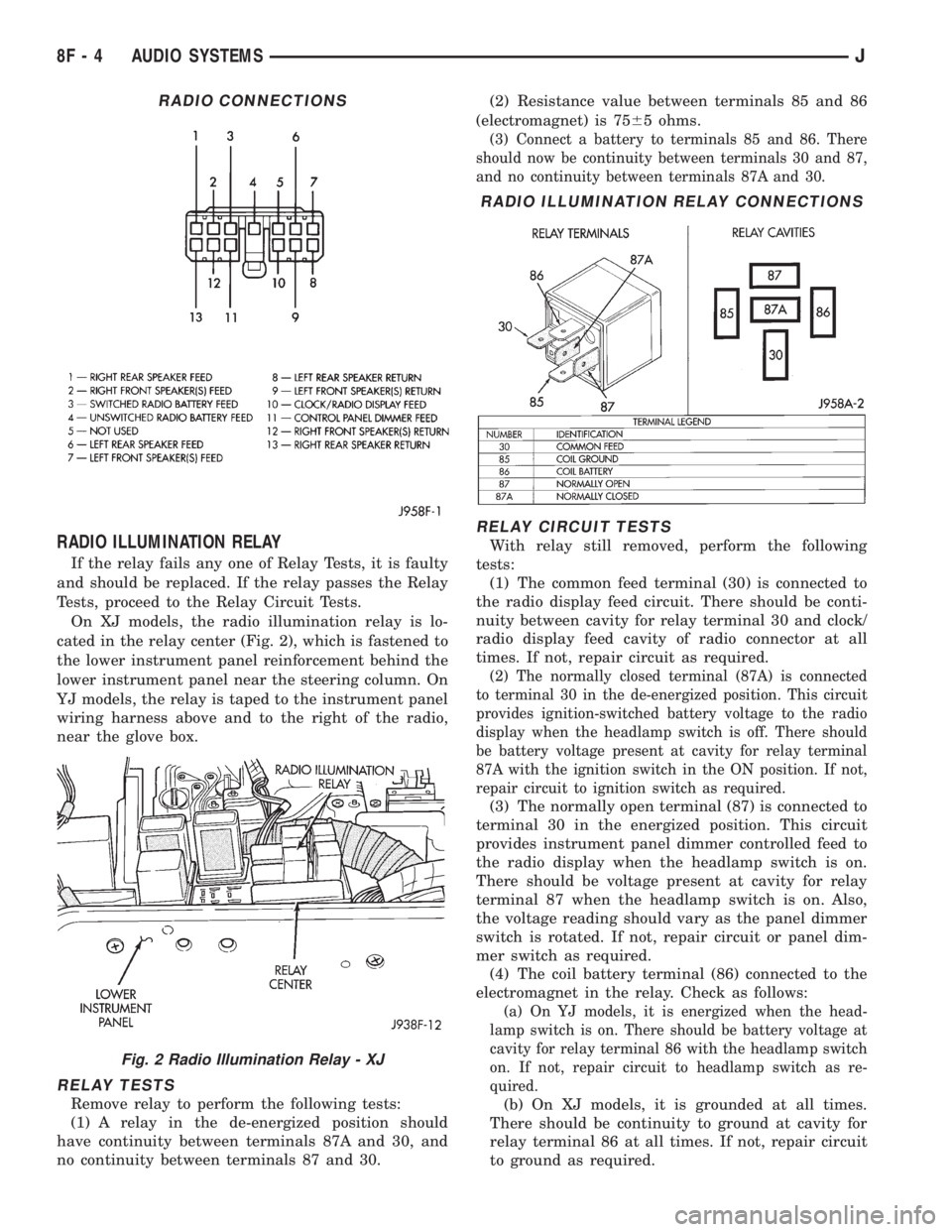
On XJ models, the radio illumination relay is lo-
cated in the relay center (Fig. 2), which is fastened to
the lower instrument panel reinforcement behind the
lower instrument panel near the steering column. On
YJ models, the relay is taped to the instrument panel
wiring harness above and to the right of the radio,
near the glove box.
RELAY TESTS
Remove relay to perform the following tests:
(1) A relay in the de-energized position should
have continuity between terminals 87A and 30, and
no continuity between terminals 87 and 30.(2) Resistance value between terminals 85 and 86
(electromagnet) is 7565 ohms.
(3) Connect a battery to terminals 85 and 86. There
should now be continuity between terminals 30 and 87,
and no continuity between terminals 87A and 30.
RELAY CIRCUIT TESTS
With relay still removed, perform the following
tests:
(1) The common feed terminal (30) is connected to
the radio display feed circuit. There should be conti-
nuity between cavity for relay terminal 30 and clock/
radio display feed cavity of radio connector at all
times. If not, repair circuit as required.
(2) The normally closed terminal (87A) is connected
to terminal 30 in the de-energized position. This circuit
provides ignition-switched battery voltage to the radio
display when the headlamp switch is off. There should
be battery voltage present at cavity for relay terminal
87A with the ignition switch in the ON position. If not,
repair circuit to ignition switch as required.
(3) The normally open terminal (87) is connected to
terminal 30 in the energized position. This circuit
provides instrument panel dimmer controlled feed to
the radio display when the headlamp switch is on.
There should be voltage present at cavity for relay
terminal 87 when the headlamp switch is on. Also,
the voltage reading should vary as the panel dimmer
switch is rotated. If not, repair circuit or panel dim-
mer switch as required.
(4) The coil battery terminal (86) connected to the
electromagnet in the relay. Check as follows:
(a) On YJ models, it is energized when the head-
lamp switch is on. There should be battery voltage at
cavity for relay terminal 86 with the headlamp switch
on. If not, repair circuit to headlamp switch as re-
quired.
(b) On XJ models, it is grounded at all times.
There should be continuity to ground at cavity for
relay terminal 86 at all times. If not, repair circuit
to ground as required.
RADIO CONNECTIONS
Fig. 2 Radio Illumination Relay - XJ
RADIO ILLUMINATION RELAY CONNECTIONS
8F - 4 AUDIO SYSTEMSJ
Page 405 of 2158
(5) The coil ground terminal (85) is connected to
the electromagnet in the relay. Check as follows:
(a) On YJ models, it is grounded at all times.
There should be continuity to ground at cavity for
relay terminal 85 at all times. If not, repair circuit
to ground as required.
(b) On XJ models, it is energized when the head-
lamp switch is on. There should be battery voltage
at cavity for relay terminal 85 with the headlamp
switch on. If not, repair circuit to headlamp switch
as required.
ANTENNA
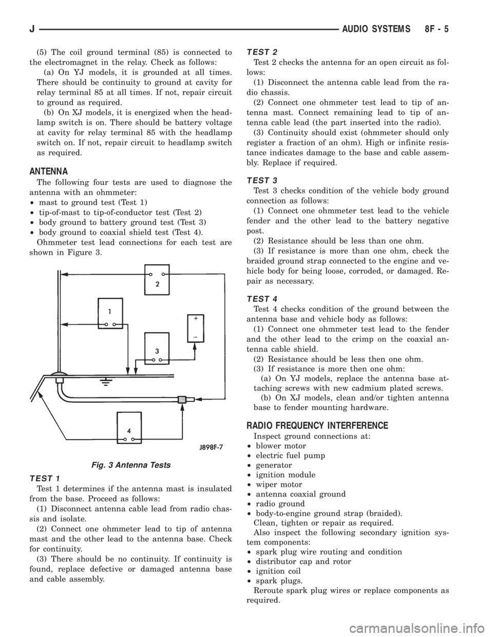
The following four tests are used to diagnose the
antenna with an ohmmeter:
²mast to ground test (Test 1)
²tip-of-mast to tip-of-conductor test (Test 2)
²body ground to battery ground test (Test 3)
²body ground to coaxial shield test (Test 4).
Ohmmeter test lead connections for each test are
shown in Figure 3.
TEST 1
Test 1 determines if the antenna mast is insulated
from the base. Proceed as follows:
(1) Disconnect antenna cable lead from radio chas-
sis and isolate.
(2) Connect one ohmmeter lead to tip of antenna
mast and the other lead to the antenna base. Check
for continuity.
(3) There should be no continuity. If continuity is
found, replace defective or damaged antenna base
and cable assembly.
TEST 2
Test 2 checks the antenna for an open circuit as fol-
lows:
(1) Disconnect the antenna cable lead from the ra-
dio chassis.
(2) Connect one ohmmeter test lead to tip of an-
tenna mast. Connect remaining lead to tip of an-
tenna cable lead (the part inserted into the radio).
(3) Continuity should exist (ohmmeter should only
register a fraction of an ohm). High or infinite resis-
tance indicates damage to the base and cable assem-
bly. Replace if required.
TEST 3
Test 3 checks condition of the vehicle body ground
connection as follows:
(1) Connect one ohmmeter test lead to the vehicle
fender and the other lead to the battery negative
post.
(2) Resistance should be less than one ohm.
(3) If resistance is more than one ohm, check the
braided ground strap connected to the engine and ve-
hicle body for being loose, corroded, or damaged. Re-
pair as necessary.
TEST 4
Test 4 checks condition of the ground between the
antenna base and vehicle body as follows:
(1) Connect one ohmmeter test lead to the fender
and the other lead to the crimp on the coaxial an-
tenna cable shield.
(2) Resistance should be less then one ohm.
(3) If resistance is more then one ohm:
(a) On YJ models, replace the antenna base at-
taching screws with new cadmium plated screws.
(b) On XJ models, clean and/or tighten antenna
base to fender mounting hardware.
RADIO FREQUENCY INTERFERENCE
Inspect ground connections at:
²blower motor
²electric fuel pump
²generator
²ignition module
²wiper motor
²antenna coaxial ground
²radio ground
²body-to-engine ground strap (braided).
Clean, tighten or repair as required.
Also inspect the following secondary ignition sys-
tem components:
²spark plug wire routing and condition
²distributor cap and rotor
²ignition coil
²spark plugs.
Reroute spark plug wires or replace components as
required.
Fig. 3 Antenna Tests
JAUDIO SYSTEMS 8F - 5
Page 427 of 2158
TURN SIGNAL AND HAZARD WARNING SYSTEMS
CONTENTS
page page
DIAGNOSIS............................. 3
GENERAL INFORMATION.................. 1SERVICE PROCEDURES................... 5
GENERAL INFORMATION
Following are general descriptions of the major
components in the XJ (Cherokee)/YJ (Wrangler)
model turn signal and hazard warning systems. Refer
to Group 8W - Wiring Diagrams for complete circuit
descriptions and diagrams.
TURN SIGNAL SYSTEM
With the ignition switch in the ON or ACCESSORY
position and the turn signal switch lever (YJ) or
multi-function switch control lever (XJ) moved up
(right turn) or down (left turn), the turn signal sys-
tem is activated.
When the turn signal system is activated, the se-
lected (right or left) turn signal indicator lamp, front
park/turn signal lamp and rear tail/stop/turn signal
lamp bulb filaments will flash. With the headlamp
switch in the OFF position, the turn and front side
marker lamps flash in unison. With the headlamp
switch in the ON position, the turn and front side
marker lamps flash alternately.
HAZARD WARNING SYSTEM
The hazard warning is activated by a switch button
located below the ignition lock cylinder (YJ) or on the
top of the steering column (XJ) between the steering
wheel and the instrument panel. The hazard warning
flasher (YJ) or combination flasher (XJ) receives bat-
tery feed at all times, and the system is functional
regardless of ignition switch position. The hazard
warning switch button is identified with a double
triangle. On YJ models, push the switch button in to
activate the hazard warning system and pull the
button out to turn system off. On XJ models, push in
on the switch button to latch the switch and activate
the hazard warning system, and push in on the
switch button again to unlatch the switch and turn
the system off.
When the hazard warning system is activated, all
(right and left) turn signal indicator, front park/turn
signal lamp and rear tail/stop/turn signal lamp bulb
filaments will flash.
TURN SIGNAL FLASHER (YJ ONLY)
The turn signal flasher is located in the fuseblock
module. It contains one fixed contact point and one
contact point attached to a flexible bimetal arm. The
contact points are normally closed. When a turn sig-
nal is activated, current flows through the flasher. As
current flows through the bimetal arm it heats and
flexes to pull the contact points open, stopping cur-
rent flow. As the bimetal arm cools it straightens,
until the contact points close and the cycle repeats.
The standard flasher is designed to handle the cur-
rent flow requirements of the factory installed light-
ing. If supplemental lighting is added to the turn
signal circuits such as when towing a trailer with
lights, the current flow through the flasher increases.
This causes the flash rate to increase. It is recom-
mended that the standard flasher be replaced with a
heavy-duty (hazard warning) flasher when supple-
mental lighting is added.
However, when a turn signal bulb fails with a stan-
dard flasher, the remaining bulbs in that circuit will
light, but not flash. This will give the driver an indi-
cation to check the turn signal bulbs. Because a
heavy-duty flasher has different internal circuitry, a
failed bulb will not prevent the remaining bulbs in
the circuit from flashing. Therefore, it is recom-
mended that an occasional visual inspection of exte-
rior turn signal lamp operation be performed when a
heavy-duty flasher is installed.
HAZARD WARNING FLASHER (YJ ONLY)
The hazard warning flasher is located in the fuse-
block module. The hazard warning flasher contains
two normally open contact points mounted to two
flexible arms. A bimetal strip is attached between the
two arms. When the hazard warning is activated,
current flows through the flasher. As the current
flows through the bimetal strip it heats and pulls the
flexible arms together until the contact points close,
JTURN SIGNAL AND HAZARD WARNING SYSTEMS 8J - 1
Page 428 of 2158
allowing current flow to the lamps. As the bimetal
strip cools, the contact points are pushed open and
the cycle repeats.
COMBINATION FLASHER (XJ ONLY)
The combination flasher functions as both the turn
signal and hazard warning flasher on XJ models. The
combination flasher is a smart relay that is located in
the relay center under the lower instrument panel
and inboard of the steering column. The combination
flasher can not be repaired. If faulty, it must be
replaced.
The combination flasher is designed to handle the
current flow requirements of the factory installed
lighting. If supplemental lighting is added to the turn
signal circuits such as when towing a trailer with
lights, the combination flasher will automatically
compensate. This allows the flash rate to remain the
same, regardless of electrical load increases. However,
if a bulb fails in the turn signal or hazard warning
circuits, the flash rate of the remaining bulbs in that
circuit will increase to 120 flashes per minute or
higher.
TURN SIGNAL/HAZARD WARNING SWITCH
(YJ ONLY)
The turn signal and hazard warning switches are
combined into a single unit mounted within the upper
steering column bowl and beneath the steering wheel.
The turn signal lever on the left side of the steering
column is moved up or down to select the right or left
turn signal switch position. The turn signals will only
operate with the ignition switch in the ACCESSORY
or ON position.
The hazard warning button on the right side of the
steering column is pushed in to turn the hazard
warning system on, or pulled out to turn the system
off. The hazard warning system will operate regard-
less of ignition switch position. The turn signal/haz-
ard warning switch can not be repaired. If faulty, the
entire unit must be replaced.
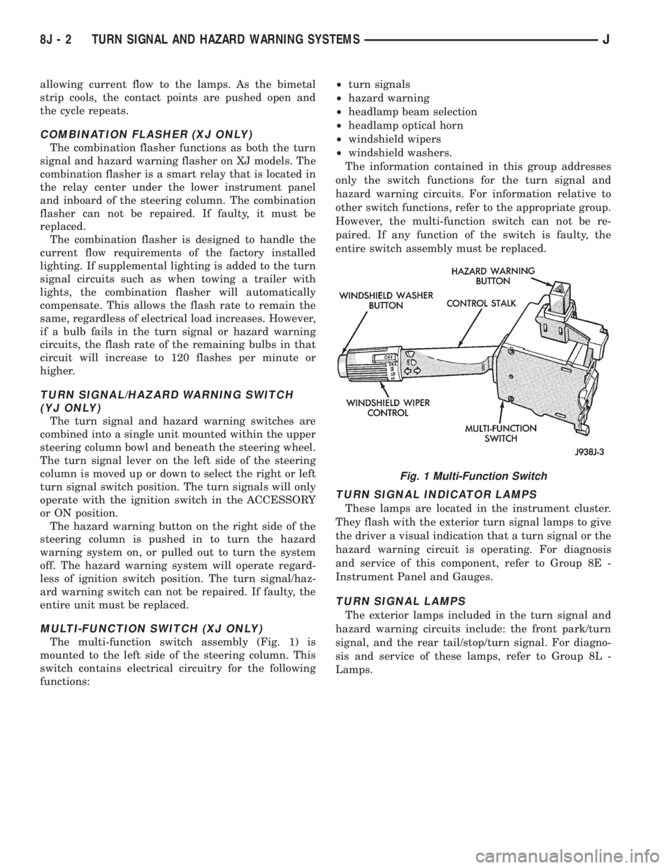
MULTI-FUNCTION SWITCH (XJ ONLY)
The multi-function switch assembly (Fig. 1) is
mounted to the left side of the steering column. This
switch contains electrical circuitry for the following
functions:²turn signals
²hazard warning
²headlamp beam selection
²headlamp optical horn
²windshield wipers
²windshield washers.
The information contained in this group addresses
only the switch functions for the turn signal and
hazard warning circuits. For information relative to
other switch functions, refer to the appropriate group.
However, the multi-function switch can not be re-
paired. If any function of the switch is faulty, the
entire switch assembly must be replaced.
TURN SIGNAL INDICATOR LAMPS
These lamps are located in the instrument cluster.
They flash with the exterior turn signal lamps to give
the driver a visual indication that a turn signal or the
hazard warning circuit is operating. For diagnosis
and service of this component, refer to Group 8E -
Instrument Panel and Gauges.
TURN SIGNAL LAMPS
The exterior lamps included in the turn signal and
hazard warning circuits include: the front park/turn
signal, and the rear tail/stop/turn signal. For diagno-
sis and service of these lamps, refer to Group 8L -
Lamps.
Fig. 1 Multi-Function Switch
8J - 2 TURN SIGNAL AND HAZARD WARNING SYSTEMSJ
Page 434 of 2158
(24) Pry up locking tabs of steering column connec-
tor and remove connector from column bracket.
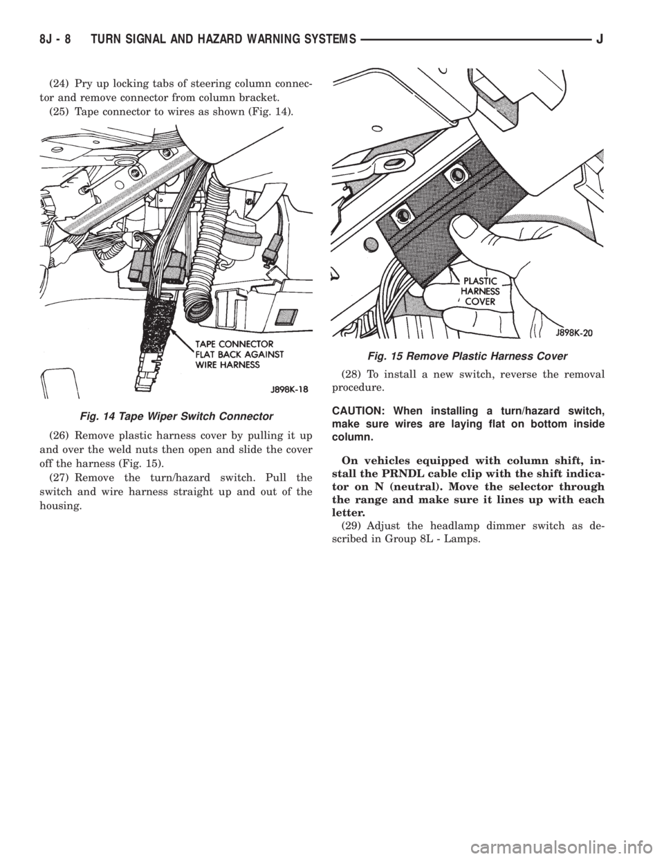
(25) Tape connector to wires as shown (Fig. 14).
(26) Remove plastic harness cover by pulling it up
and over the weld nuts then open and slide the cover
off the harness (Fig. 15).
(27) Remove the turn/hazard switch. Pull the
switch and wire harness straight up and out of the
housing.(28) To install a new switch, reverse the removal
procedure.
CAUTION: When installing a turn/hazard switch,
make sure wires are laying flat on bottom inside
column.
On vehicles equipped with column shift, in-
stall the PRNDL cable clip with the shift indica-
tor on N (neutral). Move the selector through
the range and make sure it lines up with each
letter.
(29) Adjust the headlamp dimmer switch as de-
scribed in Group 8L - Lamps.
Fig. 15 Remove Plastic Harness Cover
Fig. 14 Tape Wiper Switch Connector
8J - 8 TURN SIGNAL AND HAZARD WARNING SYSTEMSJ