1995 JEEP XJ warning
[x] Cancel search: warningPage 41 of 2158

DRIVETRAIN
INDEX
page page
Automatic Transmission.................... 23
Clutch and Brake Pedal Bushings............. 22
Clutch Master Cylinder..................... 22
Drive Shafts............................. 26Front and Rear Axles...................... 24
Manual Transmission...................... 22
Rubber and Plastic Hoses/Tubing............. 26
Transfer Case (4WD Vehicles)................ 24
CLUTCH AND BRAKE PEDAL BUSHINGS
If the clutch and brake pedal mechanism squeaks,
the pivot bushings should be lubricated. Use Mopar
Multi-Purpose Lubricant, or an equivalent. Refer to
Group 5, Brakes for location of bushings.
CLUTCH MASTER CYLINDER
LEVEL INSPECTION
WARNING: DO NOT ALLOW PETROLEUM OR WA-
TER BASE LIQUIDS TO CONTAMINATE CLUTCH
FLUID, SEAL DAMAGE AND CLUTCH FAILURE CAN
RESULT.
The clutch reservoir level should be inspected when
other underhood service is performed. (Fig. 1)
The fluid level is determined by its height in rela-
tion to the level indicator ring (Fig. 2) located inside
the reservoir. Add fluid until the height is level with
the indicator ring.
FLUID SPECIFICATION
Use Mopar, Brake And Hydraulic Clutch Fluid or
equivalent. Use only brake fluid conforming to DOT
3, Federal, Department of Transportation specifica-
tion. To avoid fluid contamination, use fluid from a
properly sealed container.CAUTION: Never use reclaimed brake fluid or fluid
from an unsealed container. In addition, do not use
fluid from a container that has been opened and al-
lowed to stand for an extended length of time.
Moisture in the air can be absorbed by the fluid,
which causes dilution with loss of effectiveness.
MANUAL TRANSMISSION
The manual transmission should be inspected for
oil leaks and proper oil level when other under vehi-
cle service is performed.
LUBRICANT SPECIFICATION
When it becomes necessary to add to or change the
lube oil in a Jeep manual transmission, use SAE
75W-90, API Quality Grade GL-5 gear lubricant.
LUBRICANT LEVEL
The fill-hole plug for all manual transmissions is
located on the right side of the case (Fig. 3). Deter-
mine the lubricant level according to the following
procedure.
(1) Remove the fill-hole plug (Fig. 3) from the
transmission. The lube oil should be level with the
bottom edge of the fill hole. The level can be slightly
below the bottom edge of the fill hole if the lube oil is
cold.
Fig. 1 Clutch Reservoir LocationÐTypical
Fig. 2 Hydraulic Clutch Fluid LevelÐTypical
0 - 22 LUBRICATION AND MAINTENANCEJ
Page 42 of 2158

If the transmission is warm, lube oil could
drip out of the fill hole. This is acceptable but
the lube oil should not gush out of the fill hole.
(2) If not acceptable, raise the lube oil level to the
bottom edge of the transmission fill hole.
Add lube oil in small amounts to raise the
level.
(3) Install the fill-hole plug in the transmission.
Tighten the plug with 37 Nzm (27 ft. lbs.) torque.
LUBE OIL CHANGE
When it becomes necessary to change manual
transmission lube oil, use the following procedure.
(1) Raise and support the vehicle.
(2) Remove the fill-hole plug from the transmis-
sion.
(3) Place a container to collect the lube oil under
the transmission drain-hole plug.
(4) Remove the drain-hole plug and drain the lube
oil from the transmission into the container.
Care should be exercised when disposing
used lube oil after it has been drained from a
transmission.
(5) Install the drain-hole plug in the transmission.
Tighten the plug with 37 Nzm (27 ft. lbs.) torque.
(6) Fill the transmission until the lube oil begins to
drip out of the fill hole.
(7) Install the fill-hole plug in the transmission.
Tighten the plug with 37 Nzm (27 ft. lbs.) torque.
(8) Remove the support and lower the vehicle.
AUTOMATIC TRANSMISSION
The automatic transmission fluid should be
changed and bands adjusted at the intervals de-
scribed in the Maintenance Schedules section of this
Group. The automatic transmission should be in-
spected for fluid leaks and proper fluid level whenother under hood service is performed. Refer to
Group 21, Transmission for proper service proce-
dures.
CAUTION: To minimize fluid contamination, verify
that dipstick is seated in the fill tube after fluid level
reading is taken.
TO INSPECT THE TRANSMISSION FLUID
LEVEL
WARNING: USE EXTREME CAUTION WHEN THE
ENGINE IS OPERATING. DO NOT PUT YOUR
HANDS NEAR THE DRIVE BELT, PULLEYS OR FAN
BLADE. DO NOT STAND IN A DIRECT LINE WITH
THE FAN BLADE.
(1) Be sure transmission fluid is at normal operat-
ing temperature. Normal operating temperature is
reached after approximately 15 miles (25km) of oper-
ation.
(2) Position the vehicle on a level surface. This is
important for an accurate fluid level check.
(3) While sitting in driver seat, apply brakes and
place gear selector in each position, then move the
selector to:
²XJ vehicles-P (Park).
²YJ vehicles-N (Neutral).
(4) Apply parking brake.
(5) Raise hood and wipe off dipstick handle to pre-
vent dirt from entering fill tube. Then remove trans-
mission fluid level indicator (dipstick) and wipe clean
with a wiping cloth.
(6) Install dipstick and verify it is seated in fill
hole or tube.
(7) Remove dipstick, with handle above tip, take
fluid level reading. If the vehicle has been driven for
at least 15 minutes before inspecting fluid level,
transmission can be considered hot and reading
should be in the OK area. If vehicle has run for less
than 15 minutes and more than 60 seconds transmis-
sion can be considered warm and reading should be
above MIN mark. Add fluid only if level is below
MIN mark on dipstick when transmission is warm
(Fig. 4).
CAUTION: Do not overfill automatic transmission,
leakage or damage can result.
AUTOMATIC TRANSMISSION FLUID
SPECIFICATION
When it becomes necessary to add fluid or when
the ATF is replaced, use:
²MOPAR Dexron IIE/Mercon ATFonlyfor AW-4
automatic transmissions (XJ vehicles).
²MOPAR ATF PLUS type 7176 (YJ vehicles).
Fig. 3 Manual Transmission Fill- & Drain-Hole
PlugsÐTypical
JLUBRICATION AND MAINTENANCE 0 - 23
Page 48 of 2158
hose unless the caliper must also be removed
for maintenance.Support the caliper with a
hanger to prevent brake fluid hose damage.
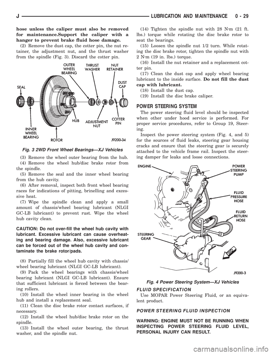
(2) Remove the dust cap, the cotter pin, the nut re-
tainer, the adjustment nut, and the thrust washer
from the spindle (Fig. 3). Discard the cotter pin.
(3) Remove the wheel outer bearing from the hub.
(4) Remove the wheel hub/disc brake rotor from
the spindle.
(5) Remove the seal and the inner wheel bearing
from the hub cavity.
(6) After removal, inspect both front wheel bearing
races for indications of pitting, brinelling and exces-
sive heat.
(7) Wipe the spindle clean and apply a small
amount of chassis/wheel bearing lubricant (NLGI
GC-LB lubricant) to prevent rust. Wipe the wheel
hub cavity clean.
CAUTION: Do not over-fill the wheel hub cavity with
lubricant. Excessive lubricant can cause overheat-
ing and bearing damage. Also, excessive lubricant
can be forced out of the wheel hub cavity and con-
taminate the brake rotor/pads.
(8) Partially fill the wheel hub cavity with chassis/
wheel bearing lubricant (NLGI GC-LB lubricant).
(9) Pack the wheel bearings with chassis/wheel
bearing lubricant (NLGI GC-LB lubricant). Ensure
that sufficient lubricant is forced between the bear-
ing rollers.
(10) Install the wheel inner bearing in the wheel
hub and install a replacement seal.
(11) Clean the disc brake rotor contact surfaces, if
necessary.
(12) Install the wheel hub/disc brake rotor on the
spindle.
(13) Install the wheel outer bearing, the thrust
washer, and the spindle nut.(14) Tighten the spindle nut with 28 Nzm (21 ft.
lbs.) torque while rotating the disc brake rotor to
seat the bearings.
(15) Loosen the spindle nut 1/2 turn. While rotat-
ing the disc brake rotor, tighten the spindle nut with
2Nzm (19 in. lbs.) torque.
(16) Install the nut retainer and a replacement cot-
ter pin.
(17) Clean the dust cap and apply wheel bearing
lubricant to the inside surface.Do not fill the dust
cap with lubricant.
(18) Install the dust cap.
(19) Install the disc brake caliper.
POWER STEERING SYSTEM
The power steering fluid level should be inspected
when other under hood service is performed. For
proper service procedures, refer to Group 19, Steer-
ing.
Inspect the power steering system (Fig. 4, and 5)
for the sources of fluid leaks, steering gear housing
cracks and ensure that the steering gear is securely
attached to the vehicle frame rail. Inspect the steer-
ing damper for leaks and loose connections.
FLUID SPECIFICATION
Use MOPAR Power Steering Fluid, or an equiva-
lent product.
POWER STEERING FLUID INSPECTION
WARNING: ENGINE MUST NOT BE RUNNING WHEN
INSPECTING POWER STEERING FLUID LEVEL,
PERSONAL INJURY CAN RESULT.
Fig. 3 2WD Front Wheel BearingsÐXJ Vehicles
Fig. 4 Power Steering SystemÐXJ Vehicles
JLUBRICATION AND MAINTENANCE 0 - 29
Page 50 of 2158

(5) Inspect the reservoir rubber diaphragm seal for
cracks, cuts and distortion.
(6) Inspect the brake fluid tubing fittings and the
master cylinder housing for indications of fluid leak-
age. Repair as necessary.
(7) Install the brake fluid reservoir cover.
ANTI-LOCK BRAKE SYSTEMÐXJ VEHICLES
The anti-lock brake system fluid reservoir for XJ
Vehicles is located in the engine compartment at the
left side of the dash panel.
(1) Turn the ignition switch ON and allow the
pump motor to operate until it automatically de-en-
ergizes.
(2) Clean the cover before removing it.
CAUTION: Over-filling could cause fluid overflow
and possible reservoir damage when the pump mo-
tor energizes.
(3) The brake fluid level should be no lower than
the ADD indicator on the side of the reservoir (Fig.
8). If not, add brake fluid as necessary. Raise the
fluid level to the FULL indicator only. Do not over-fill
the reservoir.
(4) Turn the ignition switch OFF.
BRAKE SYSTEM INSPECTION
A brake system inspection should be included with
all brake service procedures, and also each time the
vehicle is lubricated.
(1) Inspect the brake pads and linings for excessive
wear, cracks, charred surfaces and broken rivets.
(2) Inspect brake pads and linings for contamina-
tion from brake fluid, and/or other fluids.
(3) Replace the brake pads linings if they are worn
to within 0.78 mm (1/32 in) of the rivet head.
(4) Operate the rear brake self-adjuster lever and
pivot. Test the operation of the self-adjuster screw for
ease of movement.
(5) Inspect the self-adjuster components for wear
or damage.
(6) Inspect the disc brake caliper dust boot for
damage and indications of brake fluid leakage. In-
spect the bushings and pins for corrosion, tears and a
binding condition.
(7) Pull the rear wheel cylinder dust boot back to
expose the wheel cylinder housing. Inspect for fluid
leaks. Inspect the pistons and cylinder bores.
(8) Inspect the brake differential warning valve
and housing for indications of leakage.
BRAKE FLUID HOSES/TUBING
The rubber brake fluid hoses should be inspected
for:
²Correct length
²Severe surface cracking
²Swelling
²Pulling
²Scuffing
²Excessively worn areas
If the hose has cracks or abrasions in the rub-
ber cover, the hose should be replaced.
(1) Inspect all the hoses for kinks, a distorted con-
dition and fluid leakage.
(2) Inspect the hose and tubing routing under the
vehicle. Verify that no hose/tubing is rubbing against
any exhaust or other underbody components.
PARKING BRAKE
(1) Engage the parking brake pedal and then re-
lease it.
(2) Test it for smooth operation and vehicle-holding
capability.
(3) Inspect the parking brake cables.
(4) With the parking brake released, the rear
wheels should
rotate without restriction. Adjust the parking brake
cable tension, if necessary (Fig. 9 and 10).
(5) Repair any parking brake malfunctions.
BRAKE OPERATIONAL TEST
(1) Drive the vehicle and test for proper brake ac-
tion.
Fig. 7 Reservoir Fluid LevelÐYJ (2.5L)
Fig. 8 Reservoir Fluid LevelÐYJ-XJ and Anti-Lock
Brake System
JLUBRICATION AND MAINTENANCE 0 - 31
Page 58 of 2158
even tire wear. The wheel toe position is thefinal
front wheel alignment adjustment.
²STEERING AXIS INCLINATION ANGLE is mea-
sured in degrees and is the angle that the steering
knuckles are tilted (Fig. 1). The inclination angle has
a fixed relationship with the camber angle. It will not
change except when a spindle or ball stud is dam-
aged or bent. The angle is not adjustable, the dam-
aged component(s) must be replaced to correct mis-
alignment.
WARNING: DO NOT ATTEMPT TO MODIFY ANY
SUSPENSION OR STEERING COMPONENT BY
HEATING AND BENDING.
PRE-ALIGNMENT INSPECTION
Before starting a front wheel alignment, the follow-
ing inspection and necessary corrections must be
completed.(1) Tires with the same recommended air pressure,
size, and thread wear. Refer to Group 22, Tires And
Wheels for diagnosis information.
(2) Front wheel bearings for wear and looseness.
(3) Ball studs, steering linkage pivot points and
steering gear for looseness, roughness, binding or
wear. Refer to Group 19, Steering for additional in-
formation.
(4) Front wheels for excessive radial or lateral
runout and unbalance. Refer to Group 22, Tires And
Wheels for diagnosis information.
(5) Suspension components for wear. Check compo-
nents for correct torque. Refer to Groups 2 and 3,
Suspension and Axle for additional information.
2 - 6 FRONT SUSPENSION AND AXLEJ
Page 146 of 2158
TRAC-LOK DIFFERENTIAL
OPERATION
In a conventional differential, the torque applied to
the ring gear is transmitted to the axle shafts through
the differential gears. During normal operation, the
torque transmitted to each wheel is equal at all times.
However, if one wheel spins, the opposite wheel will
generate only as much torque as the spinning wheel.
In the Trac-Lok differential, part of the ring gear
torque is transmitted through clutch packs. The clutch
packs contain multiple disc. The clutch will have radial
grooves on the plates, and concentric grooves on the
discs or bonded fiber material which is smooth.
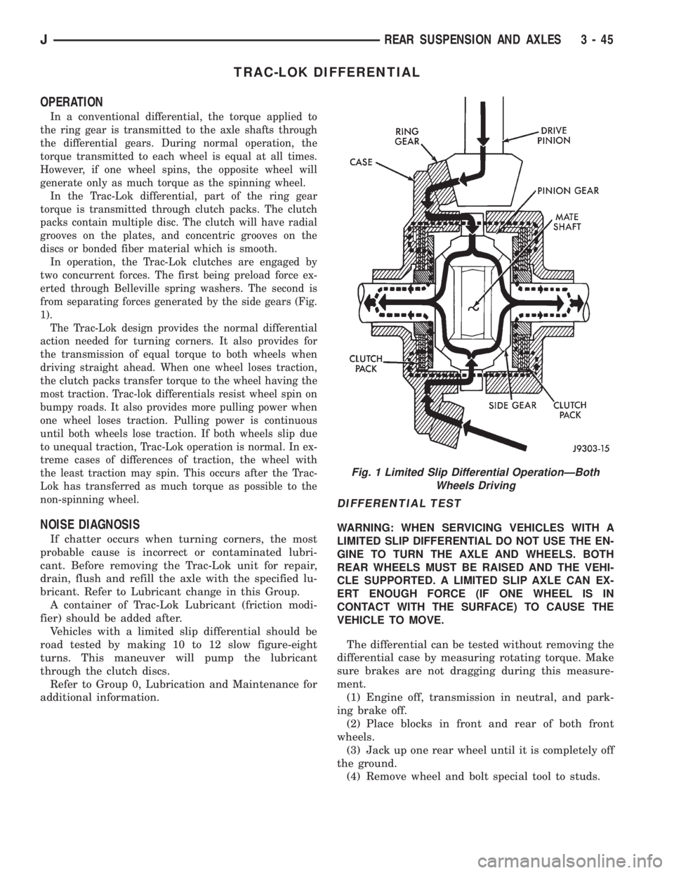
In operation, the Trac-Lok clutches are engaged by
two concurrent forces. The first being preload force ex-
erted through Belleville spring washers. The second is
from separating forces generated by the side gears (Fig.
1).
The Trac-Lok design provides the normal differential
action needed for turning corners. It also provides for
the transmission of equal torque to both wheels when
driving straight ahead. When one wheel loses traction,
the clutch packs transfer torque to the wheel having the
most traction. Trac-lok differentials resist wheel spin on
bumpy roads. It also provides more pulling power when
one wheel loses traction. Pulling power is continuous
until both wheels lose traction. If both wheels slip due
to unequal traction, Trac-Lok operation is normal. In ex-
treme cases of differences of traction, the wheel with
the least traction may spin. This occurs after the Trac-
Lok has transferred as much torque as possible to the
non-spinning wheel.
NOISE DIAGNOSIS
If chatter occurs when turning corners, the most
probable cause is incorrect or contaminated lubri-
cant. Before removing the Trac-Lok unit for repair,
drain, flush and refill the axle with the specified lu-
bricant. Refer to Lubricant change in this Group.
A container of Trac-Lok Lubricant (friction modi-
fier) should be added after.
Vehicles with a limited slip differential should be
road tested by making 10 to 12 slow figure-eight
turns. This maneuver will pump the lubricant
through the clutch discs.
Refer to Group 0, Lubrication and Maintenance for
additional information.
DIFFERENTIAL TEST
WARNING: WHEN SERVICING VEHICLES WITH A
LIMITED SLIP DIFFERENTIAL DO NOT USE THE EN-
GINE TO TURN THE AXLE AND WHEELS. BOTH
REAR WHEELS MUST BE RAISED AND THE VEHI-
CLE SUPPORTED. A LIMITED SLIP AXLE CAN EX-
ERT ENOUGH FORCE (IF ONE WHEEL IS IN
CONTACT WITH THE SURFACE) TO CAUSE THE
VEHICLE TO MOVE.
The differential can be tested without removing the
differential case by measuring rotating torque. Make
sure brakes are not dragging during this measure-
ment.
(1) Engine off, transmission in neutral, and park-
ing brake off.
(2) Place blocks in front and rear of both front
wheels.
(3) Jack up one rear wheel until it is completely off
the ground.
(4) Remove wheel and bolt special tool to studs.
Fig. 1 Limited Slip Differential OperationÐBoth
Wheels Driving
JREAR SUSPENSION AND AXLES 3 - 45
Page 153 of 2158
BRAKES
CONTENTS
page page
ABS BRAKE DIAGNOSIS................... 3
ABS OPERATION AND SERVICE............ 33
BRAKE FLUIDÐBRAKE BLEEDINGÐ
BRAKELINES AND HOSES............... 10
DISC BRAKES.......................... 45
DRUM BRAKES......................... 55
GENERAL INFORMATION.................. 1MASTER CYLINDERÐCOMBINATION VALVE . . 15
PARKING BRAKES....................... 60
POWER BRAKE BOOSTERÐBRAKE PEDALÐ
BRAKELIGHT SWITCH.................. 22
SERVICE BRAKE DIAGNOSIS............... 4
SPECIFICATIONS........................ 70
GENERAL INFORMATION
INDEX
page page
Antilock Brakes (ABS)....................... 1
Brake Components......................... 1
Brake Fluid/Lubricants/Cleaning Solvents......... 2
Brake Safety Precautions.................... 2Brake Warning Lights....................... 1
Brakelining Material........................ 1
Jeep Body Code Letters..................... 2
BRAKE COMPONENTS
Power assist front disc and rear drum brakes are
standard on Cherokee/Wrangler models. Disc brake
components consist of single piston calipers and ven-
tilated rotors. Rear drum brakes are dual shoe units
with cast brake drums.
The parking brake mechanism is lever and cable
operated. The cables are attached to levers on the
rear drum brake secondary shoes. The parking
brakes are operated by a foot pedal on YJ models and
a hand lever on XJ models.
A 205 mm dual diaphragm vacuum power brake
booster is used for all applications. Two master cylin-
ders are used; 4-cylinder YJ models have a one-piece
master cylinder. All other models have a two-piece
master cylinder with plastic reservoir.
All models are equipped with a combination valve.
The valve contains a pressure differential valve and
switch and a fixed rate rear proportioning valve.
BRAKELINING MATERIAL
Factory brakelining on all models consists of an or-
ganic base material combined with metallic particles.
The lining does not contain asbestos.
BRAKE WARNING LIGHTS
Cherokee/Wrangler models are equipped with one
or two brake warning lights. A red warning light is
standard on all models. An amber light is added on
models with ABS brakes. Both lights are located in
the instrument panel.
The red light is in circuit with the pressure differ-
ential switch (in the combination valve), and with the
parking brake switch. The light alerts the driver
when the parking brakes are applied, or when a
pressure differential exists between the front and
rear hydraulic systems. The light also illuminates for
a few seconds at start up as part of a bulb check.
The ABS warning light is amber in color and is lo-
cated in the same side of the instrument cluster as
the red warning light. The amber light only illumi-
nates when an ABS circuit fault occurs.
ANTILOCK BRAKES (ABS)
An antilock brake system (ABS) is available on
Cherokee/Wrangler models as an option. The system
is an electronically operated, all-wheel brake control
system. The ABS system is designed to prevent
wheel lockup during periods of high wheel slip brak-
ing. Refer to the antilock brake section for operation
and service information.
JBRAKES 5 - 1
Page 154 of 2158

ABS SYSTEM CHANGES
A different master cylinder, power brake booster,
and HCU are used in the 1995 Jeep ABS system.
The master cylinder reservoir has a single filler cap
and is no longer interconnected with the HCU. The
new HCU has built-in accumulators. The pedal travel
sensor has been eliminated and a new dual dia-
phragm power brake booster is used.
BRAKE FLUID/LUBRICANTS/CLEANING SOLVENTS
Recommended fluid for all Jeep vehicles is Mopar
DOT 3 brake fluid, or an equivalent meeting SAE
J1703 and DOT 3 standards.
Use Mopar Multi Mileage grease to lubricate drum
brake pivot pins and rear brakeshoe contact points
on the support plates. Use GE 661, or Dow 111 sili-
cone grease on caliper bushings and mounting bolts.
Use fresh brake fluid or Mopar brake cleaner to
clean or flush brake system components. These are
the only cleaning materials recommended.
CAUTION: Never use gasoline, kerosene, methyl or
isopropyl alcohol, paint thinner, or any fluid con-
taining mineral oil to clean brake parts. These fluids
damage rubber cups and seals. If system contami-
nation is suspected, check the fluid for dirt, discol-
oration, or separation into distinct layers. Drain and
flush the system with new brake fluid if contamina-
tion is suspected.
JEEP BODY CODE LETTERS
The body/model identification code letters for Jeep
vehicles are as follows:²Code letters XJ: Cherokee
²Code letters YJ: Wrangler/YJ
The code letters are used throughout this group to
simplify model identification and component applica-
tion.
BRAKE SAFETY PRECAUTIONS
WARNING: ALTHOUGH FACTORY INSTALLED
BRAKELINING ON JEEP VEHICLES IS MADE FROM
ASBESTOS FREE MATERIALS, SOME AFTER MAR-
KET BRAKELINING MAY CONTAIN ASBESTOS. THIS
SHOULD BE TAKEN INTO ACCOUNT WHEN RE-
PAIRING A VEHICLE WITH PRIOR BRAKE SERVICE.
WEAR A RESPIRATOR WHEN CLEANING BRAKE
COMPONENTS AS ASBESTOS FIBERS CAN BE A
HEALTH HAZARD. NEVER CLEAN WHEEL BRAKE
COMPONENTS WITH COMPRESSED AIR. USE A
VACUUM CLEANER SPECIFICALLY DESIGNED FOR
REMOVING BRAKE DUST. IF A VACUUM CLEANER
IS NOT AVAILABLE, CLEAN THE PARTS WITH WA-
TER DAMPENED SHOP RAGS. DO NOT CREATE
DUST BY SANDING BRAKELINING. DISPOSE OF
ALL DUST AND DIRT SUSPECTED OF CONTAINING
ASBESTOS FIBERS IN SEALED BAGS OR CON-
TAINERS. FOLLOW ALL SAFETY PRACTICES REC-
OMMENDED BY THE OCCUPATIONAL SAFETY AND
HEALTH ADMINISTRATION (OSHA) AND THE ENVI-
RONMENTAL PROTECTION AGENCY (EPA), FOR
HANDLING AND DISPOSAL OF ASBESTOS.
5 - 2 BRAKESJ