1995 JEEP XJ speaker
[x] Cancel search: speakerPage 923 of 2158
RADIO
RADIO
When the ignition switch is in the ACCESSORY or
RUN position, it connects circuit A1 from fuse 6 in
the Power Distribution Center (PDC) to circuit A48.
Circuit A48 powers circuit F85 through fuse 13 in the
fuse block. Circuit F85 powers the radio.
Circuit Z1 provides ground for the radio. The an-
tenna connects to the rear of the radio.
RADIO MEMORY
Circuit M1 from fuse 16 in the Power Distribution
Center (PDC) supplies power for the radio memory.
Circuit A7 from fuse 3 in the PDC supplies voltage
to fuse 16. Circuits A7 and M1 are HOT at all times.
RADIO ILLUMINATION
Circuit E2 supplies battery voltage to the radio il-
lumination lamps when the headlamps or parking
lamps are on and the dimmer switch is in the Low or
On positions.
Circuit X5 supplies battery voltage for the radio
clock and station frequency display. Circuit X5 origi-
nates at the radio illumination relay and is fed by ei-
ther circuit F85 or circuit E2 depending on the
switch position inside the relay.
When the headlamps and parking lamps are off,
the radio illumination relay is in its normal At Rest
position. In the At Rest position, the relay connects
circuit F85 from fuse 13 in the fuse block to circuit
X5.
When the headlamps or parking lamps are on, cir-
cuit L90 from the headlamp switch supplies battery
voltage to the coil side of the radio illumination relay.
Circuit Z1 provides ground for the coil side of the re-
lay.
When voltage is present on circuit L90, the radio
illumination relay switches from its At Rest position
to connect circuit E2 to circuit X5.
HELPFUL INFORMATION
²Circuit A48 supplies voltage to fuse 13 in the fuse
block for circuit F85 when the ignition switch is in
the ACCESSORY or RUN positions. In these posi-
tions, the ignition switch connects circuit A1 from
fuse 6 in the PDC to circuit A48.²Circuit A3 from fuse 5 in the PDC supplies power
to the fuse block for fuse 9. Fuse 9 protects circuit
L7. When the headlamps or parking lamps are ON,
the headlamp switch connects circuit L7 to circuit
L90. When the adjustable dimmer switch is in the
LOW to ON positions, it internally connects circuit
L7 to circuit E2. Circuit E2 powers fuse 25 in the
fuse block. Circuit E2 continues through fuse 25.
POWER ANTENNA
The Power Antenna Relay supplies power to raise
and lower the antenna. Circuit F60 from fuse 7 in
the fuse block powers the relay. Circuit Z1 provides
ground for the relay.
When the radio is turned on, circuit X60 from the
radio energizes the relay to raise the antenna.
SPEAKERS
Circuit X53 feeds the left front speakers. Circuit
X55 is the return from the speakers to the radio.
Circuit X54 feeds the right front speakers. Circuit
X56 is the return from the speakers to the radio.
Circuit X51 feeds the left rear speaker. Circuit X57
is the return from the speaker to the radio.
Circuit X52 feeds the right rear speaker. Circuit
X58 is the return from the speaker to the radio.
DIAGRAM INDEX
Component Page
Fuse 3 (PDC).........................8W-47-2, 4
Fuse 5 (PDC).......................8W-47-2, 4, 5
Fuse 6 (PDC).........................8W-47-2, 4
Fuse 7 (PDC).........................8W-47-2, 4
Fuse 9 (Fuse Block)...................8W-47-2, 4, 5
Fuse 13 (Fuse Block)....................8W-47-2, 4
Fuse 16 (PDC)........................8W-47-2, 4
Fuse 25 (Fuse Block)....................8W-47-2, 4
Headlamp Switch.......................8W-47-2, 4
Ignition Switch..........................8W-47-2
LCD Relay...........................8W-47-3, 5
Power Antenna..........................8W-47-6
Power Antenna Relay......................8W-47-6
Radio...........................8W-47-2 thru 8
Speakers............................8W-47-7, 8
J8W-47 AUDIO SYSTEMÐXJ-RHD 8W - 47 - 1
Page 1085 of 2158
SPLICE LOCATIONS
GENERAL INFORMATION
This section provides illustrations identifying the
general location of the splices in this vehicle. A spliceindex is provided. Use the wiring diagrams in each
section for splice number identification. Refer to the
index for the proper splice number.
SPLICE LOCATIONS
Splice
NumberLocations Fig.
S101......InT/OforHorn and Radiator Fan Motor....2
S102......Before T/O for A/C Low Pressure Switch....2
S103......Before T/O for A/C Low Pressure Switch....2
S104......After T/O for A/C Low Pressure Switch.....2
S105......After T/O for A/C Low Pressure Switch.....2
S106......Before T/O for MAP Sensor............2
S107......Before T/O for MAP Sensor............2
S108......Before T/O for Injector No. 4...........4
S109......Before T/O for Injector No. 6...........4
S110......After T/O for MAP Sensor.............2
S111......After T/O for MAP Sensor.............2
S112......After T/O for Injectors................3
S113......After T/O for Injectors................3
S114......Before T/O for Brake Warning Switch......3
S115......Before T/O for Brake Warning Switch......3
S116......Before T/O for Brake Warning Switch......3
S117......InT/OforDash Connectors, Before Grommet .3
S118......InT/OforDash Connectors, Before Grommet .3
S119......InT/OforABSControl Module, After Grommet .5
S120......After T/O for Underhood Lamp..........3
S121......Before T/O for PDC..................3
S122......Before T/O for PDC..................3
S123......Before T/O for Ambient Air Temperature
Sensor........................3
S124......Near T/O for Ignition Coil and Generator....4
S125......After T/O for Left Fog Lamp............1
S126......Near Clip for Middle of Gille Opening......1
S127......Before T/O for Right Fog Lamp..........1
S201......Before T/O for Right Door Speaker (With ABS) .6
S201......Before T/O for Right Door Speaker (Without ABS)
...............................6
S202......Before T/O for Right Door Speaker (With ABS) .6
S202......Before T/O for Right Door Speaker
(Without ABS)....................6
S203......After T/O for Right Door Jamb Switch (With
ABS)...........................6
S204......Before T/O for Stop Lamp Switch (With ABS) .6
S205......Before T/O for Stop Lamp Switch (With ABS) .6
S205......Before T/O for Stop Lamp Switch (Without ABS)
...............................6
S206......Before T/O for Stop Lamp Switch (With ABS) .6
S206......After T/O for Heated Rear Window Switch and
Fog Lamp Switch (Without ABS).........6
S207......Before T/O for Headlamp Switch (With ABS) .6
S208......InT/OforHeated Rear Window Switch and Fog
Lamp Switch (With ABS)..............6Splice
NumberLocations Fig.
S208......Before T/O for Headlamp Switch
(Without ABS)....................6
S209......After T/O for Heated Rear Window Switch
and Fog Lamp Switch (With ABS).......6
S209......After T/O for Right Door Jamb Switch
(Without ABS)....................6
S210......After T/O for Heated Rear Window Switch and
Fog Lamp Switch (With ABS)...........6
S210......Before T/O for Headlamp Switch
(Without ABS)....................6
S211......After T/O for Antenna (With ABS)........6
S211......After T/O for A/C-Heater Mode Switch
(Without ABS)....................6
S212......InT/OforRelay Center (With ABS).......6
S212......InT/OforRelay Center (Without ABS).....6
S213......InT/OforRelay Center (With ABS).......6
S214......After T/O for Wiper Switch (With ABS).....6
S214......After T/O for A/C-Heater Mode Switch
(Without ABS)...................6
S215......After T/O for A/C-Heater Blower Motor
Switch (With ABS).................6
S216......After T/O for A/C-Heater Mode Switch
(With ABS)......................6
S216......After T/O for A/C-Heater Blower Motor
Switch (Without ABS)...............6
S217......After T/O for A/C-Heater Mode Switch
(With ABS)......................6
S217......After T/O for A/C-Heater Mode Switch
(Without ABS)....................6
S218......After T/O for A/C-Heater Mode Switch
(With ABS).....................6
S218......InT/OforRelay Center (Without ABS).....6
S219......After T/O for Glove Box (With ABS).......6
S220......After T/O for A/C-Heater Mode Switch
(With ABS)......................6
S220......After T/O for A/C-Heater Mode Switch
(Without ABS)....................6
S221......After T/O for Blower Motor Resistor Block
(With ABS)......................6
S222......Before T/O for Stop Lamp Switch
(Without ABS)....................6
S223......After T/O for Heated Rear Window Switch
and Fog Lamp Switch (Without ABS).....6
S224......After T/O for Glove Box (Without ABS).....6
S301......Bottom of Left Front Door Opening.......9
S302......Bottom of Left Front Door Opening.......9
S303......Bottom of Left Front Door Opening.......9
S304......Bottom of Left Front Door Opening.......9
J8W-95 SPLICE LOCATIONSÐXJ-RHD 8W - 95 - 1
Page 1180 of 2158
RADIO
RADIO MEMORY
Circuit M1 from the Ignition Off Draw (IOD) fuse
in the Power Distribution Center (PDC) supplies
power for the radio memory. The IOD fuse is re-
moved during vehicle shipping to prevent excessive
battery draw.
Circuit A4 from fuse 8 in the PDC supplies voltage
to the IOD fuse in cavity 12. Circuit A4 is HOT at all
times.
RADIO ILLUMINATION
Circuit E2 supplies battery voltage to the radio il-
lumination lamps when the headlamps or parking
lamps are ON and the dimmer switch is in the LOW
or ON positions.
Circuit E22 supplies battery voltage for the radio
clock and station frequency display. Circuit E22 orig-
inates at the radio illumination relay and is fed by
either circuit F30 or circuit E2 depending on the
switch position inside the relay.
When the headlamps and parking lamps are OFF,
the radio illumination relay is in its normal At-Rest
position. In the At Rest position, the relay connects
circuit F30 from fuse 7 in the fuse block to circuit
E22.
When the headlamps or parking lamps are ON, cir-
cuit L7 from the headlamp switch supplies battery
voltage to the coil side of the radio illumination relay.
Circuit Z1 provides ground for the coil side of the re-
lay.
When voltage is present on circuit L7, the radio il-
lumination relay switches from its at rest position to
connect circuit E2 to circuit E22.
HELPFUL INFORMATION
²Circuit A31 supplies voltage to the fuse block for
circuit F30 when the ignition switch is in the AC-
CESSORY or RUN positions. In these positions the
ignition switch connects circuit A1 from fuse 4 in the
PDC to circuit A31. Circuit A31 powers a bus bar in
the fuse block that feeds circuit F30 through fuse 7.
²Circuit A6 from fuse 3 in the PDC supplies power
to the fuse block for fuse 8. Fuse 8 protects circuit
F33. When the headlamps or parking lamps are ON,the headlamp switch connects circuit F33 to circuit
L7. When the adjustable dimmer switch is in the
LOW to ON positions, it connects circuit L7 to circuit
E1. Circuit E1 powers fuse 10 in the fuse block. Fuse
10 in the fuse block protects circuit E2.
SPEAKERS
Circuit X53 feeds the speaker on the left side of the
instrument panel. Circuit X55 is the return from the
speaker to the radio.
Circuit X54 feeds the right instrument panel
speaker. Circuit X56 is the return from the speaker
to the radio.
The speaker feed and return circuits are double
crimped at the front speakers and continue to the
connector for the rear speakers. If the vehicle is not
equipped with the rear speaker sound bar, a jumper
is installed in the harness to simulate rear speaker
load.
Circuit X51 feeds the left rear speaker. Circuit X57
is the return from the speaker to the radio.
Circuit X52 feeds the right rear speaker. Circuit
X58 is the return from the speaker to the radio.
DIAGRAM INDEX
Component Page
Fuse 3 (PDC)...........................8W-47-3
Fuse 4 (PDC)...........................8W-47-2
Fuse 7 (Fuse Block).......................8W-47-2
Fuse 8 (Fuse Block).......................8W-47-3
Fuse 8 (PDC)...........................8W-47-2
Fuse 10 (Fuse Block)......................8W-47-3
Fuse 12 (PDC)..........................8W-47-2
Headlamp Switch.........................8W-47-3
Ignition Switch..........................8W-47-2
Left Front Speaker........................8W-47-4
Left Rear Speaker........................8W-47-5
Panel Lamp Dimmer Switch..................8W-47-3
Radio............................8W-47-2, 3, 4
Radio Illumination Relay....................8W-47-2
Right Front Speaker.......................8W-47-4
Right Rear Speaker.......................8W-47-5
J8W-47 AUDIO SYSTEMÐYJ VEHICLES 8W - 47 - 1
Page 1262 of 2158
CONNECTOR LOCATIONS
GENERAL INFORMATION
This section provides illustrations identifying com-
ponent and connector locations in the vehicle. A con-nector index is provided. Use the wiring diagrams in
each section for connector number identification. Re-
fer to the index for the proper figure number.
CONNECTOR LOCATIONS
Connector # . Color . Location Fig.
C101......BK ...RTFender Side Shield..........1
C102......BK ...RTFender Side Shield Under PDC . .1
C103......BK ...RTFender Side Shield..........1
C104......BK ...LTSide of Battery on Cowl Panel . . .1
C105 2.5L . . . NAT . . RT Rear of Engine............3
C105 4.0L . . . NAT . . RT Rear of Engine............4
C106......BK ...AtLamp...................1
C107......NAT ..Center of Cowl Panel Near
Map Sensor...............1
C108......BK ...LTKick Panel Above Park Brake . . .8
C109......BK ...Under Drivers Seat............8
C110......BK ...Under I.P.Front of Floor Tunnel....6
C111......BK ...Under I.P.Front of Floor Tunnel....6
C112......BK ...Under I.P. RT of Stop Lamp Switch .7
C113......BK ...LTFender Side Shield..........1
C114......BK ...LTSide Cowl Panel............1
C115......BK ...LTFender Side Shield..........1
C116......BK ...LTFender Side Shield..........1
C117......BK ...LTFender Side Shield..........1
C118......BK ...Bottom of Washer Reservoir......2
C119......BK ...Near Bulkhead Disconnect
2.5L only..........Not Shown
C120 2.5L . . . BK . . . Rear of Generator.............3
C120 4.0L . . . BK . . . Rear of Generator.............5
C121 2.5L . . . BK . . . RT Rear of Engine............3
C121 4.0L . . . BK . . . Rear of Generator.............4
C122......BK ...OnReceiver/Drier.............4
C123 2.5L . . . BK . . . RT Side of Engine Rear of Distributor .3
C123 4.0L . . . BK . . . RT Side of Engine Rear of Distributor .4
C124 2.5L . . . BK . . . At End of Distributor Pig Tail.....3
C124 4.0L . . . BK . . . At End of Distributor Pig Tail.....4
C125......GY ...RTSide of Transmission........5
C126......BK ...LTRear of Transmission.........5
C127......BK ...TopofFuel Tank..............9
C128......BK ...TopofRear Cross-member.......9
C129......BK ...TopofRear Cross-member.......9
C130 2.5L . . . BK . . . On Thermostat Housing.........3
C130 4.0L . . . BK . . . On Thermostat Housing.........4
C131 2.5L . . . BK . . . LT Side of Engine Bottom of Intake .3
C131 4.0L . . . BK . . . LT Side of Engine Bottom of Intake .4
C132 2.5L . . . BK . . . Injector #1.................3
C132 4.0L . . . BK . . . Injector #1.................4
C133 2.5L . . . BK . . . Injector #2.................3
C133 4.0L . . . BK . . . Injector #2.................4
C134 2.5L . . . BK . . . Injector #3.................3
C134 4.0L . . . BK . . . Injector #3.................4
C135 2.5L . . . BK . . . Injector #4.................3
C135 4.0L . . . BK . . . Injector #4.................4Connector # . Color . Location Fig.
C136......BK ...Injector #5.................4
C137......BK ...Injector #6.................4
C138 2.5L . . . BK . . . Center of Dash Panel...........1
C138 4.0L . . . BK . . . Center of Dash Panel...........1
C139......BK ...Under Bulkhead LT Side of I.P.....1
C140 2.5L . . . GY . . . LT Rear of Intake.............3
C140 4.0L . . . GY . . . LT Rear of Intake.............4
C141 2.5L . . . BK . . . Rear of Throttle Body..........3
C141 4.0L . . . BK . . . Rear of Throttle Body..........4
C142 2.5L . . . BK . . . On Throttle Body.............3
C142 4.0L . . . BK . . . On Throttle Body.............4
C143 2.5L . . . BK . . . Rear of Intake...............3
C143 4.0L . . . BK . . . Rear of Intake...............4
C144......BK ...Above Bulkhead Disconnect.......1
C145......GY ...OnPower Steering Pump........3
C146......BK ...AtHeadlamp..........Not Shown
C147......YL ...AtSide Marker Lamp..........2
C148......BK ...AtPark/Turn Lamp......Not Shown
C149......BK ...RTSide Behind Bumper.........2
C150......BK ...LTSide Behind Bumper.........2
C151......BK ...AtPark/Turn Lamp............2
C152......YL ...AtSide Marker Lamp. . . .Not Shown
C153......BK ...AtHeadlamp................2
C154......BK ...LTFender Side Shield..........2
C155......BK ...Direct Connection to Horn.......2
C156......BK ...Bottom of Washer Reservoir......2
C201......BK ...LTSide of I.P...............7
C202......BK ...OnFuse Block...............7
C203......BK ...LTKick Panel................7
C204......BK ...LTKick Panel................7
C205......BK ...LTSide Kick Panel Under I.P......7
C206......BK ...AtSpeaker...........Not Shown
C207......BK ...LTofSteering Column Rear
of Cluster.................7
C208......BK ...LTSide of Steering Column......7
C209......BK ...Rear of Switch...............7
C210......BK ...Rear of Switch...............7
C211......BK ...Base of Steering Column........7
C212......BK ...AtWiper Motor..............7
C213......BK ...RTofSteering Column Under I.P. . .7
C214......BK ...RTSide of Cluster Bezel . .Not Shown
C215......BK ...Base of Steering Column........7
C216......BK ...Base of Steering Column........7
C217......BK ...RTSide of Brake Pedal Support . . .7
C218......BK ...Base of Steering Column........7
C219......BK ...Rear of Switch...............7
C220......BK ...Rear of Switch...............7
C221......BK ...Rear of Switch...............7
J8W-90 CONNECTOR LOCATIONSÐYJ VEHICLES 8W - 90 - 1
Page 1263 of 2158
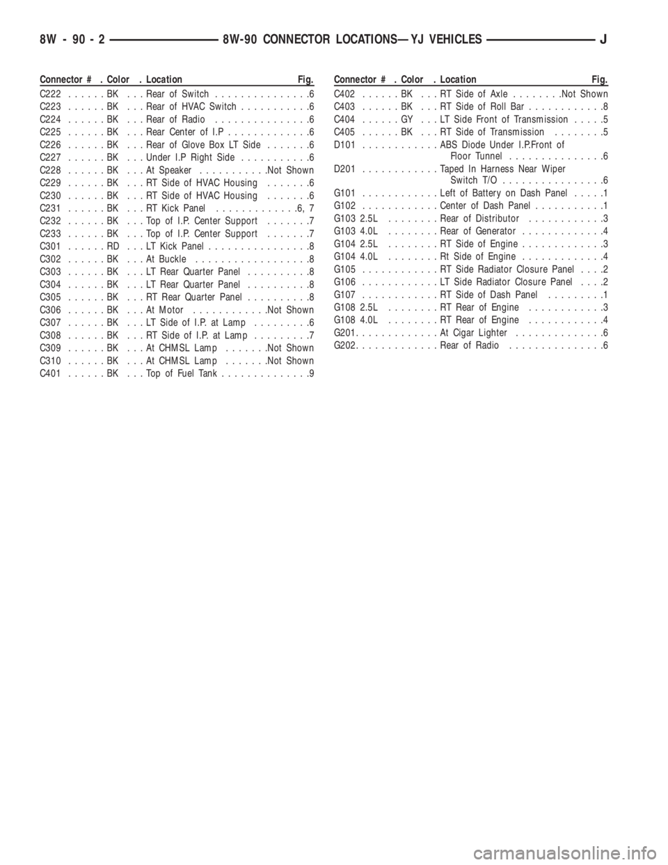
Connector # . Color . Location Fig.
C222......BK ...Rear of Switch...............6
C223......BK ...Rear of HVAC Switch...........6
C224......BK ...Rear of Radio...............6
C225......BK ...Rear Center of I.P.............6
C226......BK ...Rear of Glove Box LT Side.......6
C227......BK ...Under I.P Right Side...........6
C228......BK ...AtSpeaker...........Not Shown
C229......BK ...RTSide of HVAC Housing.......6
C230......BK ...RTSide of HVAC Housing.......6
C231......BK ...RTKick Panel.............6,7
C232......BK ...TopofI.P.Center Support.......7
C233......BK ...TopofI.P.Center Support.......7
C301......RD ...LTKick Panel................8
C302......BK ...AtBuckle..................8
C303......BK ...LTRear Quarter Panel..........8
C304......BK ...LTRear Quarter Panel..........8
C305......BK ...RTRear Quarter Panel..........8
C306......BK ...AtMotor............Not Shown
C307......BK ...LTSide of I.P. at Lamp.........6
C308......BK ...RTSide of I.P. at Lamp.........7
C309......BK ...AtCHMSL Lamp.......Not Shown
C310......BK ...AtCHMSL Lamp.......Not Shown
C401......BK ...TopofFuel Tank..............9Connector # . Color . Location Fig.
C402......BK ...RTSide of Axle........Not Shown
C403......BK ...RTSide of Roll Bar............8
C404......GY ...LTSide Front of Transmission.....5
C405......BK ...RTSide of Transmission........5
D101............ABSDiode Under I.P.Front of
Floor Tunnel...............6
D201............Taped In Harness Near Wiper
Switch T/O................6
G101............Left of Battery on Dash Panel.....1
G102............Center of Dash Panel...........1
G103 2.5L . .......Rear of Distributor............3
G103 4.0L . .......Rear of Generator.............4
G104 2.5L . .......RTSide of Engine.............3
G104 4.0L . .......RtSide of Engine.............4
G105............RTSide Radiator Closure Panel....2
G106............LTSide Radiator Closure Panel....2
G107............RTSide of Dash Panel.........1
G108 2.5L . .......RTRear of Engine............3
G108 4.0L . .......RTRear of Engine............4
G201.............AtCigar Lighter..............6
G202.............Rear of Radio...............6
8W - 90 - 2 8W-90 CONNECTOR LOCATIONSÐYJ VEHICLESJ
Page 1952 of 2158
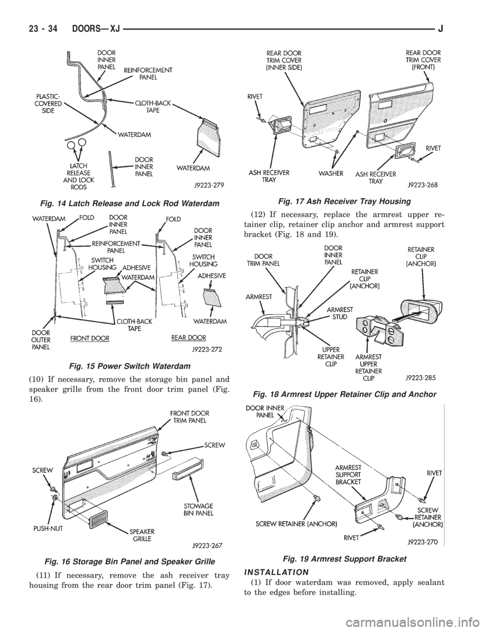
(10) If necessary, remove the storage bin panel and
speaker grille from the front door trim panel (Fig.
16).
(11) If necessary, remove the ash receiver tray
housing from the rear door trim panel (Fig. 17).(12) If necessary, replace the armrest upper re-
tainer clip, retainer clip anchor and armrest support
bracket (Fig. 18 and 19).
INSTALLATION
(1) If door waterdam was removed, apply sealant
to the edges before installing.
Fig. 14 Latch Release and Lock Rod Waterdam
Fig. 15 Power Switch Waterdam
Fig. 16 Storage Bin Panel and Speaker Grille
Fig. 17 Ash Receiver Tray Housing
Fig. 18 Armrest Upper Retainer Clip and Anchor
Fig. 19 Armrest Support Bracket
23 - 34 DOORSÐXJJ
Page 1953 of 2158
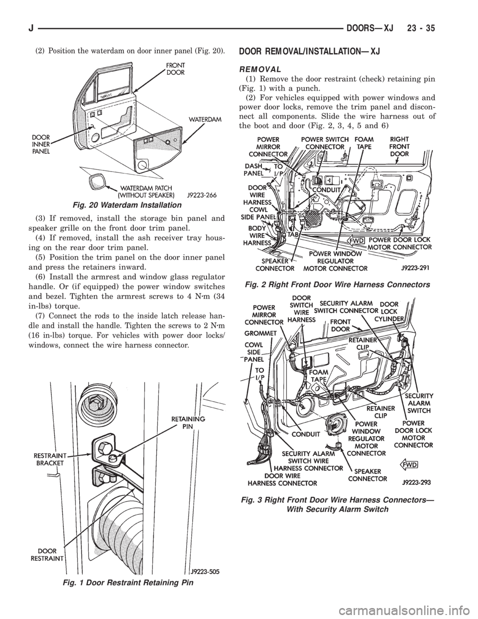
(2) Position the waterdam on door inner panel (Fig. 20).
(3) If removed, install the storage bin panel and
speaker grille on the front door trim panel.
(4) If removed, install the ash receiver tray hous-
ing on the rear door trim panel.
(5) Position the trim panel on the door inner panel
and press the retainers inward.
(6) Install the armrest and window glass regulator
handle. Or (if equipped) the power window switches
and bezel. Tighten the armrest screws to 4 Nzm (34
in-lbs) torque.
(7) Connect the rods to the inside latch release han-
dle and install the handle. Tighten the screws to 2 Nzm
(16 in-lbs) torque. For vehicles with power door locks/
windows, connect the wire harness connector.
DOOR REMOVAL/INSTALLATIONÐXJ
REMOVAL
(1) Remove the door restraint (check) retaining pin
(Fig. 1) with a punch.
(2) For vehicles equipped with power windows and
power door locks, remove the trim panel and discon-
nect all components. Slide the wire harness out of
the boot and door (Fig. 2, 3, 4, 5 and 6)
Fig. 1 Door Restraint Retaining Pin
Fig. 20 Waterdam Installation
Fig. 2 Right Front Door Wire Harness Connectors
Fig. 3 Right Front Door Wire Harness ConnectorsÐ
With Security Alarm Switch
JDOORSÐXJ 23 - 35
Page 1959 of 2158
DOOR ALIGNMENT ADJUSTMENTÐMAJOR
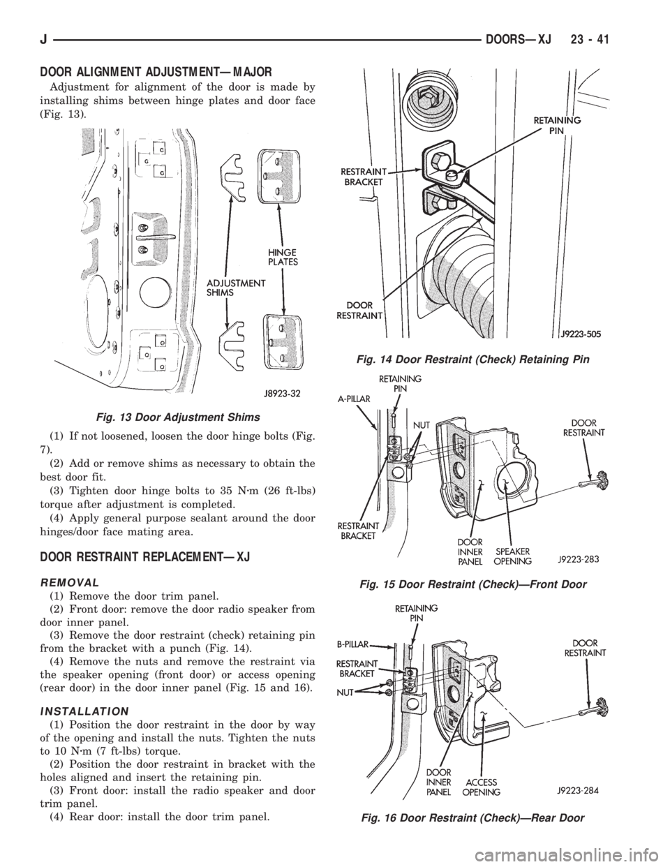
Adjustment for alignment of the door is made by
installing shims between hinge plates and door face
(Fig. 13).
(1) If not loosened, loosen the door hinge bolts (Fig.
7).
(2) Add or remove shims as necessary to obtain the
best door fit.
(3) Tighten door hinge bolts to 35 Nzm (26 ft-lbs)
torque after adjustment is completed.
(4) Apply general purpose sealant around the door
hinges/door face mating area.
DOOR RESTRAINT REPLACEMENTÐXJ
REMOVAL
(1) Remove the door trim panel.
(2) Front door: remove the door radio speaker from
door inner panel.
(3) Remove the door restraint (check) retaining pin
from the bracket with a punch (Fig. 14).
(4) Remove the nuts and remove the restraint via
the speaker opening (front door) or access opening
(rear door) in the door inner panel (Fig. 15 and 16).
INSTALLATION
(1) Position the door restraint in the door by way
of the opening and install the nuts. Tighten the nuts
to 10 Nzm (7 ft-lbs) torque.
(2) Position the door restraint in bracket with the
holes aligned and insert the retaining pin.
(3) Front door: install the radio speaker and door
trim panel.
(4) Rear door: install the door trim panel.
Fig. 14 Door Restraint (Check) Retaining Pin
Fig. 15 Door Restraint (Check)ÐFront Door
Fig. 16 Door Restraint (Check)ÐRear Door
Fig. 13 Door Adjustment Shims
JDOORSÐXJ 23 - 41