1995 JEEP XJ parking brake
[x] Cancel search: parking brakePage 156 of 2158
SERVICE BRAKE DIAGNOSIS
INDEX
page page
Brake Drag............................... 6
Brake Fade.............................. 6
Brake Fluid Contamination................... 7
Brake Noise.............................. 7
Brake Pull............................... 6
Brake Warning Light Operation................ 5
Brakes Do Not Hold After Driving Through Deep
Water Puddles........................... 7
Component Inspection...................... 5
Contaminated Brakelining.................... 7
Diagnosing Parking Brake Malfunctions.......... 8
Diagnosis Procedures....................... 4
General Information........................ 4Hard Pedal or High Pedal Effort............... 6
Low Pedal............................... 5
Master Cylinder/Power Booster Test............ 8
Pedal Falls Away.......................... 5
Pedal Pulsation (Non-ABS Brakes Only)......... 6
Power Booster Check Valve Test............... 9
Power Booster Vacuum Test.................. 9
Preliminary Brake Check..................... 4
Rear Brake Grab.......................... 7
Road Testing............................. 5
Spongy Pedal............................. 5
Wheel and Tire Problems.................... 7
GENERAL INFORMATION
The diagnosis information in this section covers
service brake components which include:
²disc brake calipers
²disc brakeshoes
²drum brake wheel cylinders
²drum brakeshoes and brake drums
²drum brake support plates
²parking brake mechanism
²master cylinder/combination valve
²vacuum power brake booster
²brake pedal and brakelight switch
²brake warning light
DIAGNOSIS PROCEDURES
Service brake diagnosis involves determining if a
problem is related to a mechanical, hydraulic or vac-
uum operated component. A preliminary brake check,
followed by road testing and component inspection
are needed to determine a problem cause.
Road testing will either verify proper brake opera-
tion or confirm the existence of a problem. Compo-
nent inspection will, in most cases, identify the
actual part responsible for a problem.
The first diagnosis step is the preliminary brake
check. This involves inspecting fluid level, parking
brake action, wheel and tire condition, checking for
obvious leaks or component damage and testing
brake pedal response. A road test will confirm or
deny the existence of a problem. The final diagnosis
procedure involves road test analysis and a visual in-
spection of brake components.
PRELIMINARY BRAKE CHECK
(1) If amber ABS light is illuminated, refer to ABS
Brake System Diagnosis. If red warning light is illu-
minated, or if neither warning light is illuminated,
continue with brake check.(2) Inspect condition of tires and wheels. Damaged
wheels and worn, damaged, or underinflated tires
can cause pull, shudder, tramp and a condition simi-
lar to grab.
(3) If complaint was based on noise when braking,
check suspension components. Jounce front and rear
of vehicle and listen for noise that might be caused
by loose, worn, or damaged suspension or steering
components.
(4) Inspect brake fluid level:
(a) If vehicle has one-piece master cylinder, fluid
level should be within 6 mm (1/4 in.) of reservoir
rim.
(b) If vehicle has nylon reservoir with single
filler cap, correct level is to FULL mark on side of
reservoir. Acceptable level is between FULL and
ADD marks.
(c) Remember that fluid level in the reservoir
compartments will decrease in proportion to nor-
mal lining wear. However, if fluid level is abnor-
mally low, look for leaks at calipers, wheel
cylinders, brakelines and master cylinder.
(5) Inspect brake fluid condition:
(a) Fluid should be free of foreign material.Note
that brake fluid tends to darken over time.
This is normal and should not be mistaken for
contamination. If fluid is clear of foreign ma-
terial, it is OK.
(b) If fluid is highly discolored, or appears to con-
tain foreign material, drain out a sample with a
clean suction gun. Pour sample in a glass container
and note condition described in step (c).
(c) If fluid separates into layers, obviously con-
tains oil, or a substance other than brake fluid,
system seals and cups will have to be replaced and
hydraulic system flushed.
(6) Check parking brake operation. Verify free
movement and full release of cables and foot pedal or
5 - 4 SERVICE BRAKE DIAGNOSISJ
Page 157 of 2158
hand lever. Also note if vehicle was being operated
with parking brake partially applied (this will cause
red light to remain on).
(7) Check brake pedal operation. Verify that pedal
does not bind and has adequate free play. If pedal
lacks free play, check pedal and power booster for be-
ing loose or for bind condition. Do not road test until
condition is corrected.
(8) If components inspected look OK, road test ve-
hicle.
ROAD TESTING
(1) If amber warning light is on, problem is with
antilock system component. Refer to antilock diagno-
sis section.
(2) If red warning light is not on, proceed to step
(4).
(3) If red warning light is on, proceed as follows:
(a) See if parking brakes are applied. If brakes
are applied, release them and proceed to step (4).
(b) Note if brake pedal is abnormally low. If
pedal is definitely low and red light is still on,
check front/rear hydraulic circuits for leak.Do not
road test. Inspect and repair as needed.
(4) Check brake pedal response with transmission
in Neutral and engine running. Pedal should remain
firm under steady foot pressure. If pedal falls away,
do not road test as problem is in master cylinder, or
HCU on ABS models. If pedal holds firm, proceed to
next step.
(5) During road test, make normal and firm brake
stops in 25-35 mph range. Note faulty brake opera-
tion such as hard pedal, pull, grab, drag, noise, fade,
etc.
(6) Return to shop and inspect brake components.
Refer to inspection and diagnosis information.
COMPONENT INSPECTION
Fluid leak points and dragging brake units can
usually be located without removing any components.
The area around a leak point will be wet with fluid.
The components at a dragging brake unit (wheel,
tire, rotor) will be quite warm or hot to the touch.
Other brake problem conditions will require compo-
nent removal for proper inspection. Raise the vehicle
and remove the necessary wheels for better visual ac-
cess.
During component inspection, pay particular atten-
tion to heavily rusted/corroded brake components
(e.g. rotors, caliper pistons, brake return/holddown
springs, support plates, etc.).
Heavy accumulations of rust may be covering se-
vere damage to a brake component. It is wise to re-
move surface rust in order to accurately determine
the depth of rust penetration and damage. Light sur-
face rust is fairly normal and not a major concern (as
long as it is removed). However, heavy rust buildup,especially on high mileage vehicles may cover struc-
tural damage to such important components as
brakelines, rotors, support plates, and brake boost-
ers. Refer to the wheel brake service procedures in
this group for more information.
BRAKE WARNING LIGHT OPERATION
The red brake warning light will illuminate under
the following conditions:
²for 2-3 seconds at startup as part of normal bulb
check
²when parking brakes are applied
²low pedal caused by leak in front/rear brake hy-
draulic circuit
If the red light remains on after startup, first ver-
ify that the parking brakes are fully released. Then
check pedal action and fluid level. A red light plus
low pedal indicates the pressure differential switch
and valve have been actuated due to a system leak.
On models with ABS brakes, the amber warning
light only illuminates when an ABS malfunction has
occurred. The ABS light operates independently of
the red warning light.
PEDAL FALLS AWAY
A brake pedal that falls away under steady foot
pressure is generally the result of a system leak. The
leak point could be at a brakeline, fitting, hose,
wheel cylinder, or caliper. Internal leakage in the
master cylinder caused by worn or damaged piston
cups, may also be the problem cause.
If leakage is severe, fluid will be evident at or
around the leaking component. However internal
leakage in the master cylinder will not be physically
evident. Refer to the cylinder test procedure at the
end of this section.
LOW PEDAL
If a low pedal is experienced, pump the pedal sev-
eral times. If the pedal comes back up, worn lining
and worn rotors or drums are the most likely causes.
However, if the pedal remains low and the red warn-
ing light is on, the likely cause is a leak in the hy-
draulic system.
A decrease in master cylinder fluid level may only
be the result of normal lining wear. Fluid level will
drop somewhat as lining wear occurs. It is a result of
the outward movement of caliper and wheel cylinder
pistons to compensate for normal wear.
SPONGY PEDAL
Air in the system is the usual cause of a spongy
pedal. Brake drums machined way beyond allowable
limits (too thin), or substandard brake lines and
hoses can also cause a condition similar to a spongy
JSERVICE BRAKE DIAGNOSIS 5 - 5
Page 160 of 2158
produce a condition similar to grab as the tire loses
and recovers traction.
Flat-spotted tires can cause vibration and wheel
tramp and generate shudder during brake operation.
A tire with internal damage such as a severe bruise
or ply separation can cause vibration and pull. The
pull will be magnified when braking.
DIAGNOSING PARKING BRAKE MALFUNCTIONS
Adjustment Mechanism
Parking brake adjustment is controlled by a ca-
ble tensioner mechanism. The cable tensioner,
once adjusted at the factory, will not need further
attention under normal circumstances. There are
only two instances when adjustment is required.
The first is when a new tensioner, or cables have
been installed. And the second, is when the ten-
sioner and cables are disconnected for access to
other brake components.
Parking Brake Switch And Warning Light Illumination
The parking brake switch on the lever, or foot
pedal, is in circuit with the red warning light. The
switch will illuminate the red light only when the
parking brakes are applied. If the light remains on
after parking brake release, the switch or wires are
faulty, or cable tensioner adjustment is incorrect.
If the red light comes on while the vehicle is in mo-
tion and brake pedal height decreases, a fault has oc-
curred in the front or rear brake hydraulic system.
Parking Brake problem Causes
In most cases, the actual cause of an improperly
functioning parking brake (too loose/too tight/wont
hold), can be traced to a drum brake component.
The leading cause of improper parking brake
operation, is excessive clearance between the
brakeshoes and the drum surface. Excessive
clearance is a result of: lining and/or drum
wear; oversize drums; or inoperative shoe ad-
juster components.
Excessive parking brake lever travel (sometimes de-
scribed as a loose lever or too loose condition), is the re-
sult of worn brakeshoes/drums, improper brakeshoe
adjustment, or incorrectly assembled brake parts.
A ``too loose'' condition can also be caused by inop-
erative brakeshoe adjusters. If the adjusters are mis-
assembled, they will not function. In addition, since
the adjuster mechanism only works during reverse
stops, it is important that complete stops be made.
The adjuster mechanism does not operate when roll-
ing stops are made in reverse. The vehicle must be
brought to a complete halt before the adjuster lever
will turn the adjuster screw.
A condition where the parking brakes do not hold, will
most probably be due to a wheel brake component.
Items to look for when diagnosing a parking brake
problem, are:
²rear brakeshoe wear or adjuster problem
²rear brake drum wear
²brake drums machined beyond allowable diameter
(oversize)
²parking brake front cable not secured to lever
²parking brake rear cable seized
²parking brake strut reversed
²parking brake strut not seated in both shoes
²parking brake lever not seated in secondary shoe
²parking brake lever or brakeshoe bind on support
plate
²brakeshoes reversed
²adjuster screws seized
²adjuster screws reversed
²holddown or return springs misassembled or lack
tension
²wheel cylinder pistons seized
Brake drums that are machined oversize are diffi-
cult to identify without inspection. If oversize drums
are suspected, diameter of the braking surface will
have to be checked with an accurate drum gauge.
Oversize drums will cause low brake pedal and lack
of parking brake holding ability.
Improper parking brake strut and lever installation
will result in unsatisfactory parking brake operation.
Intermixing the adjuster screws will cause drag, bind
and pull along with poor parking brake operation.
Parking brake adjustment and parts replacement pro-
cedures are described in the Parking Brake section.
MASTER CYLINDER/POWER BOOSTER TEST
(1) Start engine and check booster vacuum hose
connections. Hissing noise indicates vacuum leak.
Correct any vacuum leak before proceeding.
(2) Stop engine and shift transmission into Neu-
tral.
(3) Pump brake pedal until all vacuum reserve in
booster is depleted.
(4) Press and hold brake pedal under light foot
pressure.
(a) If pedal holds firm, proceed to step (5).
(b) If pedal does not hold firm and falls away,
master cylinder is faulty due to internal leakage.
Overhaul or replace cylinder.
(5) Start engine and note pedal action.
(a) If pedal falls away slightly under light foot
pressure then holds firm, proceed to step (6).
(b) If no pedal action is discernible, or hard pedal
is noted, power booster or vacuum check valve is
faulty. Install known good check valve and repeat
steps (2) through (5).
(6) Rebuild booster vacuum reserve as follows: Re-
lease brake pedal. Increase engine speed to 1500
rpm, close throttle and immediately turn off ignition.
5 - 8 SERVICE BRAKE DIAGNOSISJ
Page 207 of 2158
DRUM BRAKES
INDEX
page page
Brake Drum Refinishing.................... 58
Drum Brake Adjustment.................... 57
Drum Brakeshoe Installation................. 55
Drum Brakeshoe Removal................... 55
Support Plate Replacement.................. 58Wheel Cylinder Installation.................. 58
Wheel Cylinder Overhaul.................... 57
Wheel Cylinder Removal.................... 57
Wheel Nut Tightening...................... 59
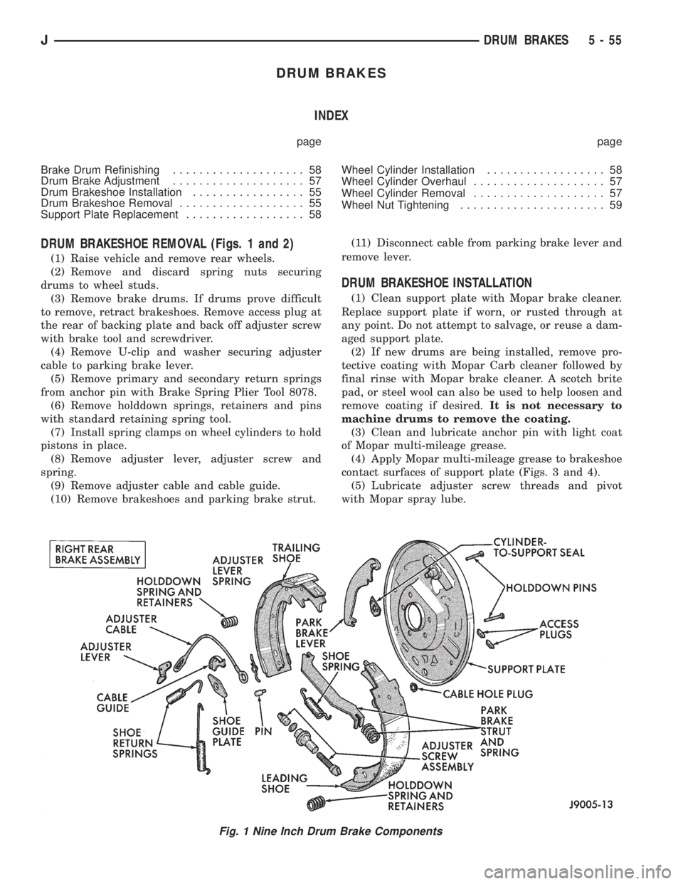
DRUM BRAKESHOE REMOVAL (Figs. 1 and 2)
(1) Raise vehicle and remove rear wheels.
(2) Remove and discard spring nuts securing
drums to wheel studs.
(3) Remove brake drums. If drums prove difficult
to remove, retract brakeshoes. Remove access plug at
the rear of backing plate and back off adjuster screw
with brake tool and screwdriver.
(4) Remove U-clip and washer securing adjuster
cable to parking brake lever.
(5) Remove primary and secondary return springs
from anchor pin with Brake Spring Plier Tool 8078.
(6) Remove holddown springs, retainers and pins
with standard retaining spring tool.
(7) Install spring clamps on wheel cylinders to hold
pistons in place.
(8) Remove adjuster lever, adjuster screw and
spring.
(9) Remove adjuster cable and cable guide.
(10) Remove brakeshoes and parking brake strut.(11) Disconnect cable from parking brake lever and
remove lever.
DRUM BRAKESHOE INSTALLATION
(1) Clean support plate with Mopar brake cleaner.
Replace support plate if worn, or rusted through at
any point. Do not attempt to salvage, or reuse a dam-
aged support plate.
(2) If new drums are being installed, remove pro-
tective coating with Mopar Carb cleaner followed by
final rinse with Mopar brake cleaner. A scotch brite
pad, or steel wool can also be used to help loosen and
remove coating if desired.It is not necessary to
machine drums to remove the coating.
(3) Clean and lubricate anchor pin with light coat
of Mopar multi-mileage grease.
(4) Apply Mopar multi-mileage grease to brakeshoe
contact surfaces of support plate (Figs. 3 and 4).
(5) Lubricate adjuster screw threads and pivot
with Mopar spray lube.
Fig. 1 Nine Inch Drum Brake Components
JDRUM BRAKES 5 - 55
Page 208 of 2158
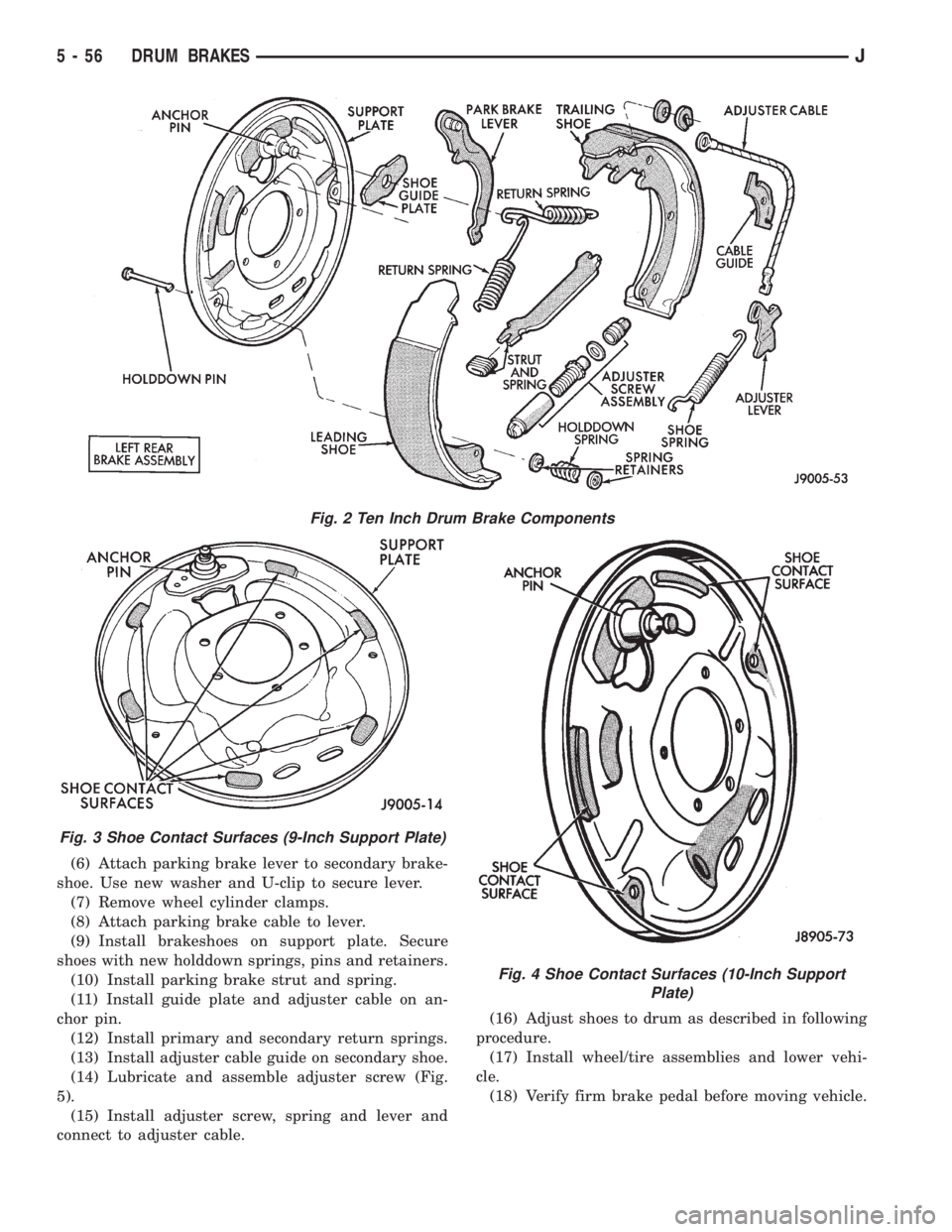
(6) Attach parking brake lever to secondary brake-
shoe. Use new washer and U-clip to secure lever.
(7) Remove wheel cylinder clamps.
(8) Attach parking brake cable to lever.
(9) Install brakeshoes on support plate. Secure
shoes with new holddown springs, pins and retainers.
(10) Install parking brake strut and spring.
(11) Install guide plate and adjuster cable on an-
chor pin.
(12) Install primary and secondary return springs.
(13) Install adjuster cable guide on secondary shoe.
(14) Lubricate and assemble adjuster screw (Fig.
5).
(15) Install adjuster screw, spring and lever and
connect to adjuster cable.(16) Adjust shoes to drum as described in following
procedure.
(17) Install wheel/tire assemblies and lower vehi-
cle.
(18) Verify firm brake pedal before moving vehicle.
Fig. 2 Ten Inch Drum Brake Components
Fig. 3 Shoe Contact Surfaces (9-Inch Support Plate)
Fig. 4 Shoe Contact Surfaces (10-Inch Support
Plate)
5 - 56 DRUM BRAKESJ
Page 210 of 2158
Do not hone cylinder bores or polish pistons.
Replace cylinder as an assembly if bore is dam-
aged.
(8) Install bleed screw.
(9) Coat cylinder bore, pistons, cups and expander
with brake fluid and reassemble cylinder compo-
nents. Be sure piston cup lips face expander.
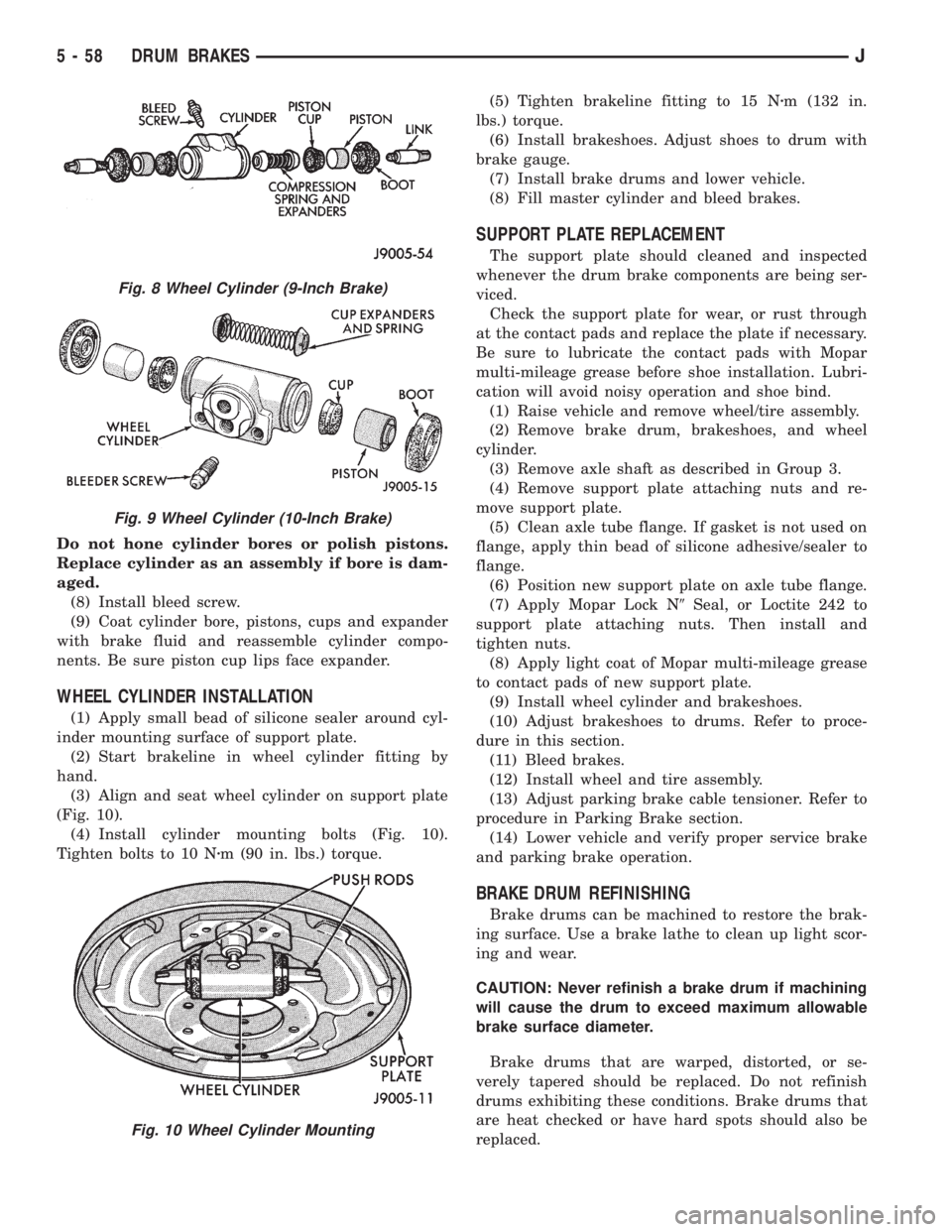
WHEEL CYLINDER INSTALLATION
(1) Apply small bead of silicone sealer around cyl-
inder mounting surface of support plate.
(2) Start brakeline in wheel cylinder fitting by
hand.
(3) Align and seat wheel cylinder on support plate
(Fig. 10).
(4) Install cylinder mounting bolts (Fig. 10).
Tighten bolts to 10 Nzm (90 in. lbs.) torque.(5) Tighten brakeline fitting to 15 Nzm (132 in.
lbs.) torque.
(6) Install brakeshoes. Adjust shoes to drum with
brake gauge.
(7) Install brake drums and lower vehicle.
(8) Fill master cylinder and bleed brakes.
SUPPORT PLATE REPLACEMENT
The support plate should cleaned and inspected
whenever the drum brake components are being ser-
viced.
Check the support plate for wear, or rust through
at the contact pads and replace the plate if necessary.
Be sure to lubricate the contact pads with Mopar
multi-mileage grease before shoe installation. Lubri-
cation will avoid noisy operation and shoe bind.
(1) Raise vehicle and remove wheel/tire assembly.
(2) Remove brake drum, brakeshoes, and wheel
cylinder.
(3) Remove axle shaft as described in Group 3.
(4) Remove support plate attaching nuts and re-
move support plate.
(5) Clean axle tube flange. If gasket is not used on
flange, apply thin bead of silicone adhesive/sealer to
flange.
(6) Position new support plate on axle tube flange.
(7) Apply Mopar Lock N9Seal, or Loctite 242 to
support plate attaching nuts. Then install and
tighten nuts.
(8) Apply light coat of Mopar multi-mileage grease
to contact pads of new support plate.
(9) Install wheel cylinder and brakeshoes.
(10) Adjust brakeshoes to drums. Refer to proce-
dure in this section.
(11) Bleed brakes.
(12) Install wheel and tire assembly.
(13) Adjust parking brake cable tensioner. Refer to
procedure in Parking Brake section.
(14) Lower vehicle and verify proper service brake
and parking brake operation.
BRAKE DRUM REFINISHING
Brake drums can be machined to restore the brak-
ing surface. Use a brake lathe to clean up light scor-
ing and wear.
CAUTION: Never refinish a brake drum if machining
will cause the drum to exceed maximum allowable
brake surface diameter.
Brake drums that are warped, distorted, or se-
verely tapered should be replaced. Do not refinish
drums exhibiting these conditions. Brake drums that
are heat checked or have hard spots should also be
replaced.
Fig. 8 Wheel Cylinder (9-Inch Brake)
Fig. 9 Wheel Cylinder (10-Inch Brake)
Fig. 10 Wheel Cylinder Mounting
5 - 58 DRUM BRAKESJ
Page 212 of 2158
PARKING BRAKES
INDEX
page page
General Service Information................. 60
Parking Brake Cable Tensioner Adjustment (XJ/YJ).. 68
Parking Brake Cable Tensioner Replacement (XJ) . 65
Parking Brake Front Cable Replacement (YJ).... 67
Parking Brake Lever Installation (XJ with Full
Console).............................. 64
Parking Brake Lever Installation (XJ with Mini
Console).............................. 63
Parking Brake Lever Installation (XJ Without
Console).............................. 65Parking Brake Lever Removal (XJ with Full Console).63
Parking Brake Lever Removal (XJ with Mini
Console).............................. 62
Parking Brake Lever Removal (XJ Without Console).64
Parking Brake Operation.................... 60
Parking Brake Pedal Installation (YJ)........... 66
Parking Brake Pedal Removal (YJ)............ 66
Parking Brake Rear Cable Replacement (XJ)..... 66
Parking Brake Rear Cable Replacement (YJ)..... 68
Parking Brake Switch...................... 68
GENERAL SERVICE INFORMATION
Parking brake adjustment is controlled by a cable ten-
sioner mechanism.
The cable tensioner, once adjusted at the factory,
should not need further adjustment under normal
circumstances. There are only two instances when
adjustment is required. The first is when a new ten-
sioner, or cables have been installed. And the second,
is when the tensioner and cables are disconnected for
access to other brake components.
PARKING BRAKE OPERATION
The rear brakes are utilized for the parking brake
function. They are actuated hydraulically during nor-
mal brake operation but are mechanically actuated
for parking brake operation.
Parking Brake Components
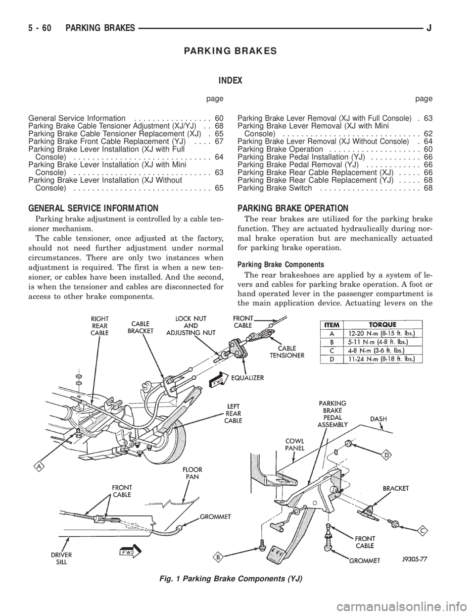
The rear brakeshoes are applied by a system of le-
vers and cables for parking brake operation. A foot or
hand operated lever in the passenger compartment is
the main application device. Actuating levers on the
Fig. 1 Parking Brake Components (YJ)
5 - 60 PARKING BRAKESJ
Page 213 of 2158
secondary brakeshoes move the shoes directly into
contact with the drum braking surface. The actuating
levers are interconnected by a system of cables and a
tensioner mechanism. The tensioner mechanism con-
trols parking brake adjustment.
A parking brake switch is used on all models. It is
mounted on the parking brake lever or foot pedal and
is actuated by movement of the lever/pedal. The
switch, which is in circuit with the red warning light
in the dash, will illuminate the warning light when-
ever the parking brakes are applied.
On XJ models, the cable tensioner is part of the lever
assembly. On YJ models, the tensioner and equalizer
are mounted in a bracket attached to the underbody.
On YJ models, the parking brake front cable is at-
tached to the foot pedal and cable tensioner. The ten-
sioner and rear cables are connected to the equalizer
(Fig. 1).
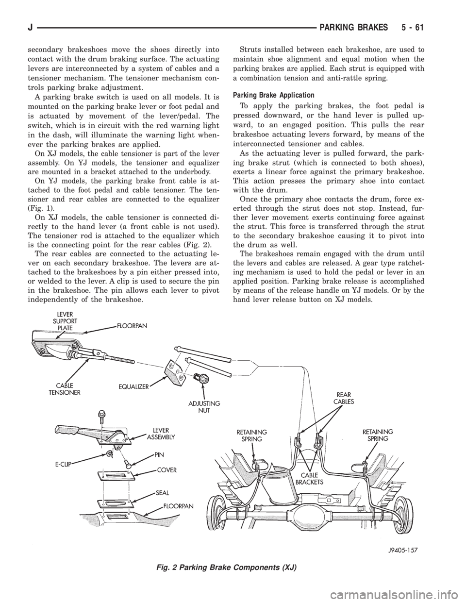
On XJ models, the cable tensioner is connected di-
rectly to the hand lever (a front cable is not used).
The tensioner rod is attached to the equalizer which
is the connecting point for the rear cables (Fig. 2).
The rear cables are connected to the actuating le-
ver on each secondary brakeshoe. The levers are at-
tached to the brakeshoes by a pin either pressed into,
or welded to the lever. A clip is used to secure the pin
in the brakeshoe. The pin allows each lever to pivot
independently of the brakeshoe.
Struts installed between each brakeshoe, are used to
maintain shoe alignment and equal motion when the
parking brakes are applied. Each strut is equipped with
a combination tension and anti-rattle spring.
Parking Brake Application
To apply the parking brakes, the foot pedal is
pressed downward, or the hand lever is pulled up-
ward, to an engaged position. This pulls the rear
brakeshoe actuating levers forward, by means of the
interconnected tensioner and cables.
As the actuating lever is pulled forward, the park-
ing brake strut (which is connected to both shoes),
exerts a linear force against the primary brakeshoe.
This action presses the primary shoe into contact
with the drum.
Once the primary shoe contacts the drum, force ex-
erted through the strut does not stop. Instead, fur-
ther lever movement exerts continuing force against
the strut. This force is transferred through the strut
to the secondary brakeshoe causing it to pivot into
the drum as well.
The brakeshoes remain engaged with the drum until
the levers and cables are released. A gear type ratchet-
ing mechanism is used to hold the pedal or lever in an
applied position. Parking brake release is accomplished
by means of the release handle on YJ models. Or by the
hand lever release button on XJ models.
Fig. 2 Parking Brake Components (XJ)
JPARKING BRAKES 5 - 61