1995 JEEP XJ Brake lamp
[x] Cancel search: Brake lampPage 115 of 2158
CAUTION: Overfilling the differential can result in
lubricant foaming and overheating.
Trac-Lok Differentials; A container of Trac-Lok lu-
bricant (friction modifier) should be added after re-
pair service or a lubricant change.
(9) Install the fill hole plug and lower the vehicle.
LIMITED SLIP DIFFERENTIAL vehicles should
be road tested by making 10 to 12 slow figure-eight
turns. This maneuver will pump the lubricant
through the clutch discs to eliminate a possible chat-
ter noise complaint.
DRIVE AXLE ASSEMBLY REPLACEMENTÐXJ
VEHICLES
REMOVAL
(1) Raise the vehicle and position support stands
under the frame rails slightly in front the springs.
(2) Remove the rear wheels.
(3) Mark the drive shaft yoke and axle pinion yoke
for alignment reference. Disconnect the drive shaft
from the axle.
(4) Disconnect the axle vent hose.
(5) Disconnect the parking brake cables at the
equalizer or backing plate.
(6) Disconnect the shock absorbers from the axle
brackets.
(7) Disconnect the brake hose at the axle junction
block.Do not disconnect the wheel cylinder tub-
ing fittings.
(8) If equipped, disconnect ABS wiring connections
at the axle.(9) Support the axle with a hydraulic jack under
the differential.
(10) Remove the spring U-bolts from the plate
brackets.
(11) Lower the jack enough to remove the axle.
INSTALLATION
CAUTION: Suspension components with rubber
bushings should be tightened with the vehicle at
normal height. It is important to have the springs
supporting the weight of the vehicle when the fas-
teners are torqued. If springs are not at their normal
ride position, vehicle ride comfort could be affected
and premature bushing wear may occur. Rubber
bushings must never be lubricated.
(1) Support the axle on a hydraulic jack under the
differential. Position the axle under the vehicle.
(2) Raise the axle and align the spring center bolts
with the locating holes in the axle pads and plate
brackets.
(3) Install the spring U-bolts through the plate
brackets and tighten to 70 Nzm (52 ft. lbs.) torque.
(4) Install ABS wiring connections (if equipped) at
the axle.
(5) Connect the brake hose at the axle junction
block.
(6) Install the shock absorbers to the axle brackets
and tighten to 62 Nzm (46 ft. lbs.) torque.
(7) Connect the parking brake cables at the equal-
izer or backing plate.
(8) Connect the vent hose to the tube fitting.
(9) Align the reference marks and connect the
drive shaft to the axle yoke. Tighten the U-joint
clamp bolts to 19 Nzm (14 ft. lbs.) torque.
(10) Check differential lubricant and add if neces-
sary.
(11) Install the wheel and tire.
(12) Bleed the brakes.
(13) Remove the supports and lower the vehicle.
DRIVE AXLE ASSEMBLY REPLACEMENTÐYJ
VEHICLES
REMOVAL
(1) Raise the vehicle and position support stands
under the frame rails slightly in front the springs.
(2) Remove the rear wheels.
(3) Mark the drive shaft yoke and axle pinion yoke
for alignment reference. Disconnect the drive shaft
from the axle.
(4) Disconnect the axle vent hose.
(5) Disconnect the parking brake cables at the
equalizer or backing plate.
(6) Disconnect the shock absorbers from the plate
brackets.
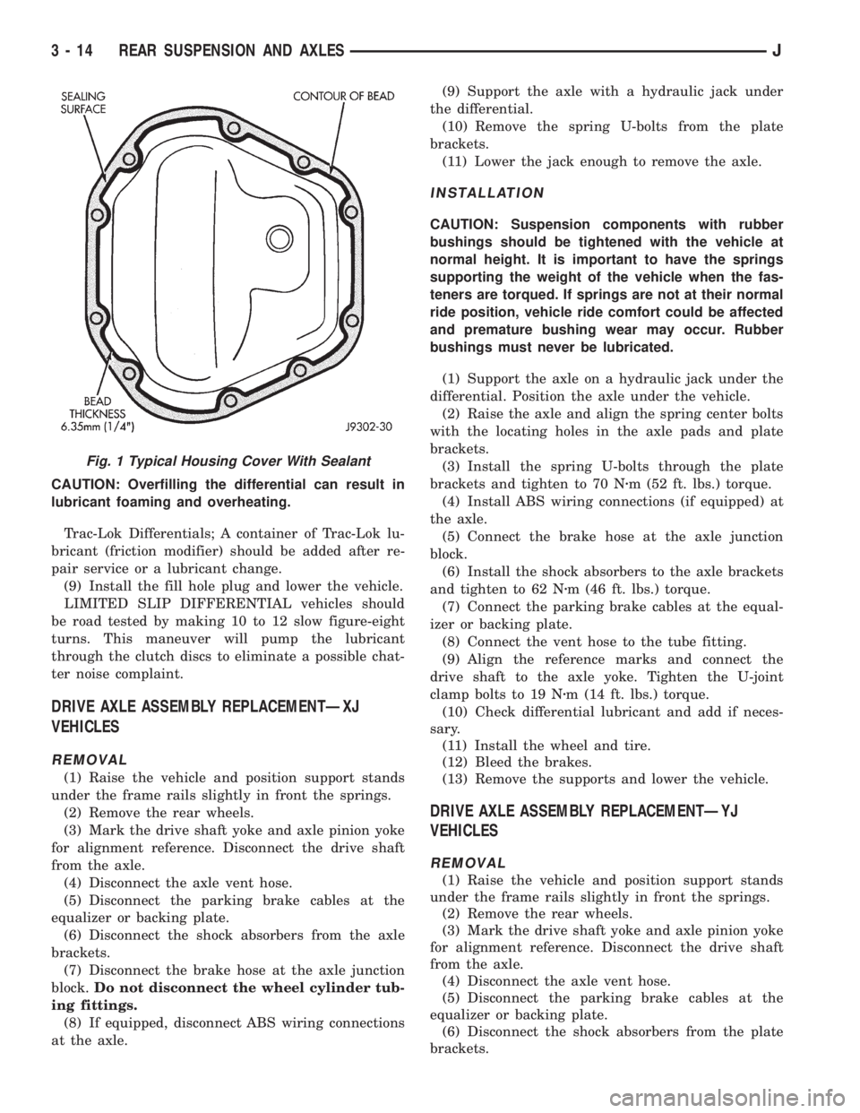
Fig. 1 Typical Housing Cover With Sealant
3 - 14 REAR SUSPENSION AND AXLESJ
Page 116 of 2158
(7) Disconnect the brake hose at the axle junction
block.Do not disconnect the wheel cylinder tub-
ing fittings.
(8) Disconnect the track bar at the axle bracket.
(9) Support the axle with a hydraulic jack under
the differential. Raise the axle just enough to relieve
the axle weight from the springs.
(10) Remove the spring U-bolts from the plate
brackets.
(11) Loosen BUT DO NOT REMOVE the bolts that
attach the spring front pivot at the frame rail brack-
ets. This will allow the springs to pivot without bind-
ing on the bushings.
(12) Disconnect shackle from the springs and lower
the springs to the surface.
(13) Lower the jack enough to remove the axle.
INSTALLATION
CAUTION: Suspension components with rubber
bushings should be tightened with the vehicle at
normal height. It is important to have the springs
supporting the weight of the vehicle when the fas-
teners are torqued. If springs are not at their normal
ride position, vehicle ride comfort could be affected
and premature bushing wear may occur. Rubber
bushings must never be lubricated.
(1) Support the axle on a hydraulic jack under the
differential. Position the axle under the vehicle.
(2) Raise the springs and install the spring shackle
bolts.Do not tighten at this time.
(3) Lower the axle and align the spring center
bolts with the locating holes in the axle pads and
plate brackets.
(4) Install the spring U-bolts through the plate
brackets and tighten to 122 Nzm (90 ft. lbs.) torque.
(5) Connect the track bar to the axle bracket and
install the bolt. Do not tighten at this time.
It is important that the springs support the
weight of the vehicle when the track bar is con-
nected. If the springs are not at their usual po-
sition, vehicle ride comfort could be affected.
(6) Connect the brake hose at the axle junction
block.
(7) Install the shock absorbers to the axle brackets
and tighten to 61 Nzm (45 ft. lbs.) torque.
(8) Connect the parking brake cables at the equal-
izer or backing plate.
(9) Connect the vent hose to the tube fitting.
(10) Align the reference marks and connect the
drive shaft to the axle yoke. Tighten the U-joint
clamp bolts to 19 Nzm (14 ft. lbs.) torque.
(11) Check differential lubricant and add if neces-
sary.
(12) Install the wheel and tire.
(13) Bleed the brakes.
(14) Remove the supports and lower the vehicle.(15) Tighten the spring front pivot bolt/nut to 142
Nzm (105 ft. lbs.) torque. Tighten the spring shackle
bolt/nut to 135 Nzm (100 ft. lbs.) torque.
(16) Tighten the track bar bolt at the axle bracket
to 142 Nzm (105 ft. lbs.) torque.
PINION SHAFT SEAL REPLACEMENT
REMOVAL
(1) Raise and support the vehicle.
(2) Remove wheel and tire assemblies.
(3) Mark the drive shaft yoke and pinion yoke for
installation alignment reference.
(4) Remove the drive shaft from the yoke.
(5) Rotate the pinion gear three or four times.
Make sure brakes are not dragging during this
procedure.
(6) Measure the amount of torque (in Newton-
meters or inch-pounds) necessary to rotate the pinion
gear with a torque wrench. Note the torque for in-
stallation reference.It must be known to properly
adjust the pinion gear bearing preload torque
after seal installation.
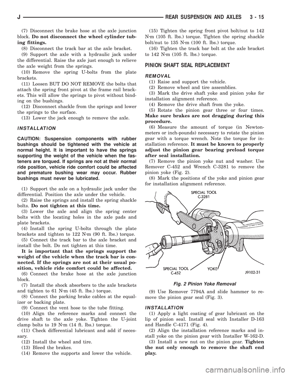
(7) Remove the pinion yoke nut and washer. Use
Remover C-452 and Wrench C-3281 to remove the
pinion yoke (Fig. 2).
(8) Mark the positions of the yoke and pinion gear
for installation alignment reference.
(9) Use Remover 7794A and slide hammer to re-
move the pinion gear seal (Fig. 3).
INSTALLATION
(1) Apply a light coating of gear lubricant on the
lip of pinion seal. Install seal with Installer D-163
and Handle C-4171 (Fig. 4).
(2) Align the installation reference marks and in-
stall yoke on the pinion gear with Installer W-162-D.
(3) Install a new nut on the pinion gear.Tighten
the nut only enough to remove the shaft end
play.
Fig. 2 Pinion Yoke Removal
JREAR SUSPENSION AND AXLES 3 - 15
Page 132 of 2158

LUBRICANT SPECIFICATIONS
Multi-purpose, hypoid gear lubricant should be
used in the 8 1/4 inch axle. The lubricant should
have MIL-L-2105C and API GL 5 quality specifica-
tions. MOPARtHypoid Gear Lubricant conforms to
both of these specifications.
²The factory installed lubricant for the 8 1/4 inch
rear axle is SAE 80W 90 gear lubricant.
²The factory installed lubricant quantity is 6762
fluid oz.
CAUTION: Overfilling the differential can result in
lubricant foaming and overheating.
Refer to Group 0, Lubrication and Maintenance for
additional information.
CAUTION: If axle is submerged in water, lubricant
must be replaced immediately to avoid possible
premature axle failure.
DRIVE AXLE ASSEMBLY REPLACEMENTÐXJ
VEHICLES
REMOVAL
(1) Raise the vehicle. Position support stands un-
der the frame rails slightly in front the springs.
(2) Remove the rear wheels.
(3) Mark the drive shaft yoke and axle pinion yoke
for alignment reference. Disconnect the drive shaft
from the axle.
(4) Disconnect the axle vent hose.
(5) Disconnect the parking brake cables at the
equalizer or backing plate.
(6) Disconnect the shock absorbers from the axle
brackets.
(7) Disconnect the brake hose at the axle junction
block.Do not disconnect the wheel cylinder tub-
ing fittings.
(8) If equipped, disconnect ABS wiring connections
at the axle.
(9) Support the axle with a hydraulic jack under
the differential.
(10) Remove the spring U-bolts from the plate
brackets.
(11) Lower the jack enough to remove the axle.
INSTALLATION
CAUTION: Suspension components with rubber
bushings should be tightened with the vehicle at
normal height. It is important to have the springs
supporting the weight of the vehicle when the fas-
teners are torqued. If springs are not at their normal
ride position, vehicle ride comfort could be affected
and premature bushing wear may occur. Rubber
bushings must never be lubricated.(1) Support the axle on a hydraulic jack under the
differential. Position the axle under the vehicle.
(2) Raise the axle and align the spring center bolts
with the locating holes in the axle pads and plate
brackets.
(3) Install the spring U-bolts through the plate
brackets and tighten to 70 Nzm (52 ft. lbs.) torque.
(4) Install ABS wiring connections (if equipped) at
the axle.
(5) Connect the brake hose at the axle junction
block.
(6) Install the shock absorbers to the axle brackets
and tighten to 62 Nzm (46 ft. lbs.) torque.
(7) Connect the parking brake cables at the equal-
izer or backing plate.
(8) Connect the vent hose to the tube fitting.
(9) Align the reference marks and connect the
drive shaft to the axle yoke. Tighten the U-joint
clamp bolts to 19 Nzm (14 ft. lbs.) torque.
(10) Check differential lubricant and add if neces-
sary.
(11) Install the wheel and tire.
(12) Bleed the brakes.
(13) Remove the supports and lower the vehicle.
LUBRICANT CHANGE
The gear lubricant will drain quicker if the vehicle
has been recently driven.
(1) Raise and support the vehicle.
(2) Remove the lubricant fill hole plug from the dif-
ferential housing cover.
(3) Remove the differential housing cover and
drain the lubricant from the housing.
(4) Clean the housing cavity with a flushing oil,
light engine oil or lint free cloth.Do not use water,
steam, kerosene or gasoline for cleaning.
(5) Remove the sealant from the housing and cover
surfaces. Use solvent to clean the mating surfaces.
(6) Apply a bead of MOPARtSilicone Rubber Seal-
ant to the housing cover (Fig. 2). Allow the sealant to
cure for a few minutes.
Install the housing cover within 5 minutes after
applying the sealant. If not installed the sealant
must be removed and another bead applied.
(7) Install the cover and any identification tag.
Tighten the cover bolts in a criss-cross pattern to 47
Nzm (35 ft. lbs.) torque.
(8) Refill the differential with Mopar Hypoid Gear
Lubricant 13 mm (1/2 in.) below the fill plug hole.
With Trac-Lok differentials, add a container of Mopar
Hypoid Gear Lubricant Additive.
CAUTION: Overfilling the differential can result in
lubricant foaming and overheating.
(9) Install the fill hole plug and lower the vehicle.
JREAR SUSPENSION AND AXLES 3 - 31
Page 135 of 2158
INSTALLATION
(1) Examine the splines on the pinion shaft for
burrs or wear.
(2) Remove any burrs and clean the shaft.
(3) Inspect the pinion yoke for cracks, worn splines
and a worn seal contact surface. Repair or replace
the yoke as necessary.
The outer perimeter of the seal is pre-coated
with a special sealant. An additional applica-
tion of sealant is not required.
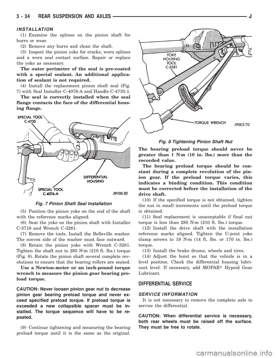
(4) Install the replacement pinion shaft seal (Fig.
7) with Seal Installer C-4076-A and Handle C-4735-1.
The seal is correctly installed when the seal
flange contacts the face of the differential hous-
ing flange.
(5) Position the pinion yoke on the end of the shaft
with the reference marks aligned.
(6) Seat the yoke on the pinion shaft with Installer
C-3718 and Wrench C-3281.
(7) Remove the tools. Install the Belleville washer.
The convex side of the washer must face outward.
(8) Retain the pinion yoke with Wrench C-3281.
Tighten the shaft nut to 285 Nzm (210 ft. lbs.) torque
(Fig. 8). Rotate the pinion shaft several complete rev-
olutions to ensure that the bearing rollers are seated.
Use a Newton-meter or an inch-pound torque
wrench to measure the pinion gear bearing pre-
load torque.
CAUTION: Never loosen pinion gear nut to decrease
pinion gear bearing preload torque and never ex-
ceed specified preload torque. If preload torque is
exceeded a new collapsible spacer must be in-
stalled. The torque sequence will have to be re-
peated.
(9) Continue tightening and measuring the bearing
preload torque until it is the same as the original.The bearing preload torque should never be
greater than 1 Nzm (10 in. lbs.) more than the
recorded value.
The bearing preload torque should be con-
stant during a complete revolution of the pin-
ion gear. If the preload torque varies, this
indicates a binding condition. This condition
must be corrected before the installation of the
drive shaft.
(10) If the specified torque is not obtained, tighten
the nut in small increments until the preload torque
is obtained.
(11) Seal replacement is unacceptable if final nut
torque is less than 285 Nzm (210 ft. lbs.) torque.
(12) Install the drive shaft with the installation
reference marks aligned. Tighten the U-joint yoke
clamp screws to 19 Nzm (14 ft. lbs. or 170 in. lbs.)
torque.
(13) Install the brake drums, wheels and tires.
(14) Adjust the hoist so that the vehicle is in a
level position. Check the differential housing lubri-
cant level. If necessary, add MOPARtHypoid Gear
Lubricant.
DIFFERENTIAL SERVICE
SERVICE INFORMATION
It is not necessary to remove the complete axle to
service the differential.
CAUTION: When differential service is necessary,
both rear wheels must be raised off the surface.
They must be free to rotate.
Fig. 7 Pinion Shaft Seal Installation
Fig. 8 Tightening Pinion Shaft Nut
3 - 34 REAR SUSPENSION AND AXLESJ
Page 168 of 2158
(2) Disconnect brake lines at master cylinder and
combination valve.
(3) Remove nuts attaching master cylinder to
booster studs.
(4) Remove master cylinder.
(5) Remove cylinder cover and drain fluid.
(6) If two-piece master cylinder reservoir requires
service, refer to reservoir replacement procedure in
this section.
MASTER CYLINDER INSTALLATION (NON-ABS)
(1) Bleed master cylinder on bench before installa-
tion. Refer to procedure in this section.
(2) If new two-piece master cylinder is being in-
stalled, remove plastic protective sleeve from primary
piston shank. Also check condition of seal at rear of
cylinder body. Reposition seal if dislodged. Replace
seal if cut, or torn.
(3) Clean cylinder mounting surface of brake booster.
Use shop towel wetted with brake cleaner for this pur-
pose. Dirt, grease, or similar materials will prevent
proper cylinder seating and could result in vacuum leak.
(4) Slide master cylinder onto brake booster studs.
(5) Install nuts attaching master cylinder to booster
studs. Tighten nuts to 25 Nzm (220 in. lbs.) torque.
(6) Connect brakelines to master cylinder and com-
bination valve (Figs. 1 and 2).
(7) Fill and bleed brake system.
COMBINATION VALVE REPLACEMENT (NON-ABS)
The combination valve is not a repairable compo-
nent. The valve is serviced as an assembly whenever
diagnosis indicates replacement is necessary.
(1) Remove air cleaner cover and hose for access to
valve, if necessary.
(2) Disconnect differential pressure switch wire at
combination valve. Do not pull switch wire to discon-
nect. Unsnap connecter lock tabs to remove.
(3) Disconnect brakelines at combination valve and
remove valve.
(4) Connect brakelines to replacement valve. Start
line fittings by hand to avoid cross threading.
Tighten fittings snug but not to required torque at
this time.
(5) Connect wire to pressure differential switch.
(6) Bleed brakes.
(7) Tighten brakeline fittings to 18-24 Nzm
(160-210 in. lbs.) torque after bleeding.
MASTER CYLINDER OVERHAUL (4-CYLINDER
MODELS)
CYLINDER DISASSEMBLY
(1) Examine cylinder cover seal. Discard seal if
torn or distorted.
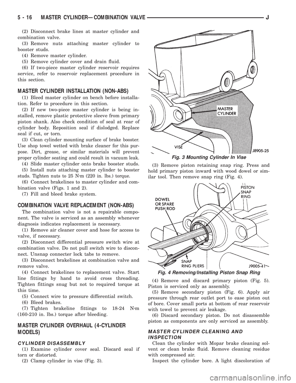
(2) Clamp cylinder in vise (Fig. 3).(3) Remove piston retaining snap ring. Press and
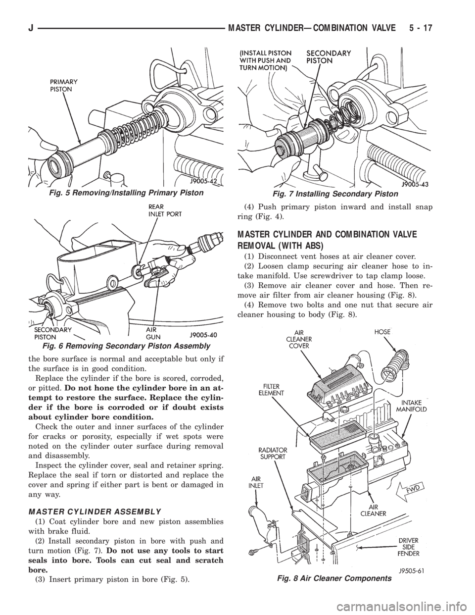
hold primary piston inward with wood dowel or sim-
ilar tool. Then remove snap ring (Fig. 4).
(4) Remove and discard primary piston (Fig. 5).
Piston is serviced only as assembly.
(5) Remove secondary piston (Fig. 6). Apply air
pressure through rear outlet port to ease piston out
of bore. Cover small ports at bottom of rear reservoir
with towel to prevent air leakage.
(6) Discard secondary piston. Do not disassemble
piston as components are only serviced as assembly.
MASTER CYLINDER CLEANING AND
INSPECTION
Clean the cylinder with Mopar brake cleaning sol-
vent or clean brake fluid. Remove cleaning residue
with compressed air.
Inspect the cylinder bore. A light discoloration of
Fig. 3 Mounting Cylinder In Vise
Fig. 4 Removing/Installing Piston Snap Ring
5 - 16 MASTER CYLINDERÐCOMBINATION VALVEJ
Page 169 of 2158
the bore surface is normal and acceptable but only if
the surface is in good condition.
Replace the cylinder if the bore is scored, corroded,
or pitted.Do not hone the cylinder bore in an at-
tempt to restore the surface. Replace the cylin-
der if the bore is corroded or if doubt exists
about cylinder bore condition.
Check the outer and inner surfaces of the cylinder
for cracks or porosity, especially if wet spots were
noted on the cylinder outer surface during removal
and disassembly.
Inspect the cylinder cover, seal and retainer spring.
Replace the seal if torn or distorted and replace the
cover and spring if either part is bent or damaged in
any way.
MASTER CYLINDER ASSEMBLY
(1) Coat cylinder bore and new piston assemblies
with brake fluid.
(2) Install secondary piston in bore with push and
turn motion (Fig. 7).Do not use any tools to start
seals into bore. Tools can cut seal and scratch
bore.
(3) Insert primary piston in bore (Fig. 5).(4) Push primary piston inward and install snap
ring (Fig. 4).
MASTER CYLINDER AND COMBINATION VALVE
REMOVAL (WITH ABS)
(1) Disconnect vent hoses at air cleaner cover.
(2) Loosen clamp securing air cleaner hose to in-
take manifold. Use screwdriver to tap clamp loose.
(3) Remove air cleaner cover and hose. Then re-
move air filter from air cleaner housing (Fig. 8).
(4) Remove two bolts and one nut that secure air
cleaner housing to body (Fig. 8).
Fig. 8 Air Cleaner Components
Fig. 5 Removing/Installing Primary Piston
Fig. 6 Removing Secondary Piston Assembly
Fig. 7 Installing Secondary Piston
JMASTER CYLINDERÐCOMBINATION VALVE 5 - 17
Page 171 of 2158
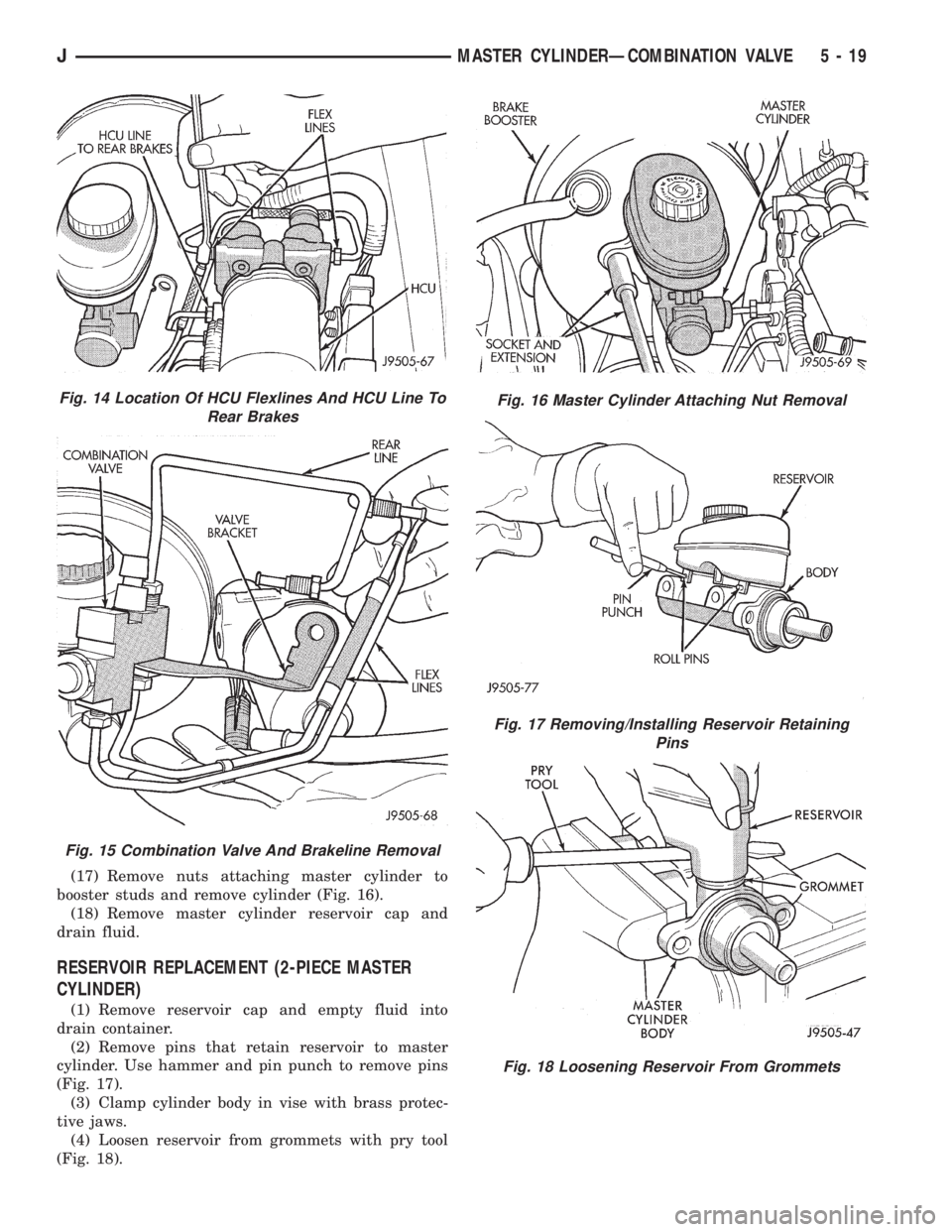
(17) Remove nuts attaching master cylinder to
booster studs and remove cylinder (Fig. 16).
(18) Remove master cylinder reservoir cap and
drain fluid.
RESERVOIR REPLACEMENT (2-PIECE MASTER
CYLINDER)
(1) Remove reservoir cap and empty fluid into
drain container.
(2) Remove pins that retain reservoir to master
cylinder. Use hammer and pin punch to remove pins
(Fig. 17).
(3) Clamp cylinder body in vise with brass protec-
tive jaws.
(4) Loosen reservoir from grommets with pry tool
(Fig. 18).
Fig. 14 Location Of HCU Flexlines And HCU Line To
Rear Brakes
Fig. 15 Combination Valve And Brakeline Removal
Fig. 16 Master Cylinder Attaching Nut Removal
Fig. 17 Removing/Installing Reservoir Retaining
Pins
Fig. 18 Loosening Reservoir From Grommets
JMASTER CYLINDERÐCOMBINATION VALVE 5 - 19
Page 176 of 2158
POWER BRAKE BOOSTER REMOVAL
(XJ WITH ABS)
(1) Disconnect vacuum and vent hoses at air
cleaner cover.
(2) Loosen clamp securing air cleaner hose to in-
take manifold. Use screwdriver to tap clamp loose.
(3) Remove air cleaner cover and hose. Then re-
move air filter from air cleaner housing (Fig. 4).
(4) Remove two bolts and one nut that secure air
cleaner housing to body (Fig. 4).
(5) Remove air cleaner housing from engine com-
partment (Fig. 4).
(6) Disconnect wire at combination valve pressure
differential switch (Fig. 5). Do not pull on wires to
disconnect. Unsnap lock tabs on connecter to remove
wires.
(7) Disconnect canister vacuum line at manifold
fitting (Fig. 6).(8) Disconnect brake booster vacuum hose at in-
take manifold fitting (Fig. 7). Move hose aside for
working clearance.
(9) Unseat small S-clip that secures brakelines
(Fig. 8).
(10) Remove front brakeline that connects master
cylinder front port to combination valve front port
(Fig. 8).
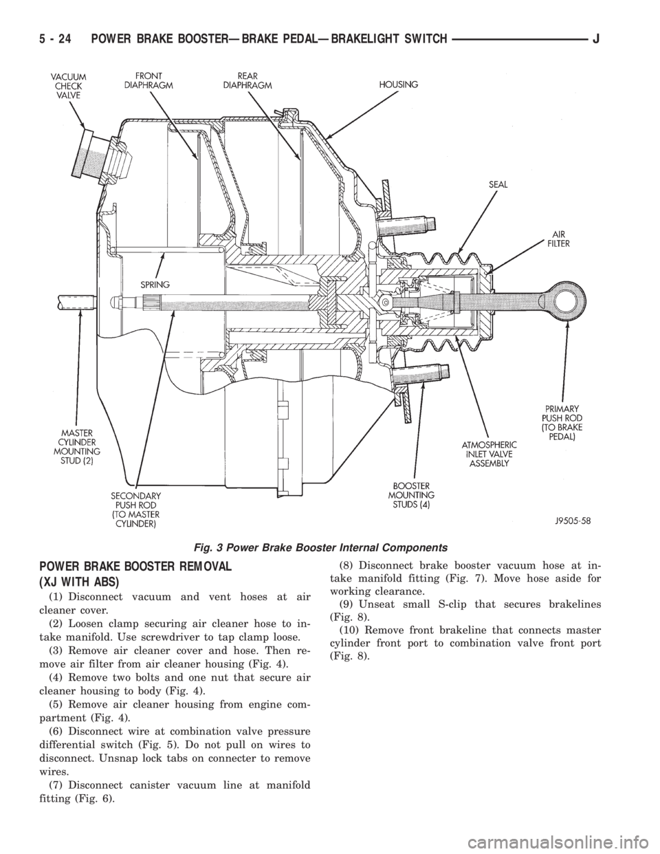
Fig. 3 Power Brake Booster Internal Components
5 - 24 POWER BRAKE BOOSTERÐBRAKE PEDALÐBRAKELIGHT SWITCHJ