1995 JEEP XJ fuse diagram
[x] Cancel search: fuse diagramPage 1180 of 2158
RADIO
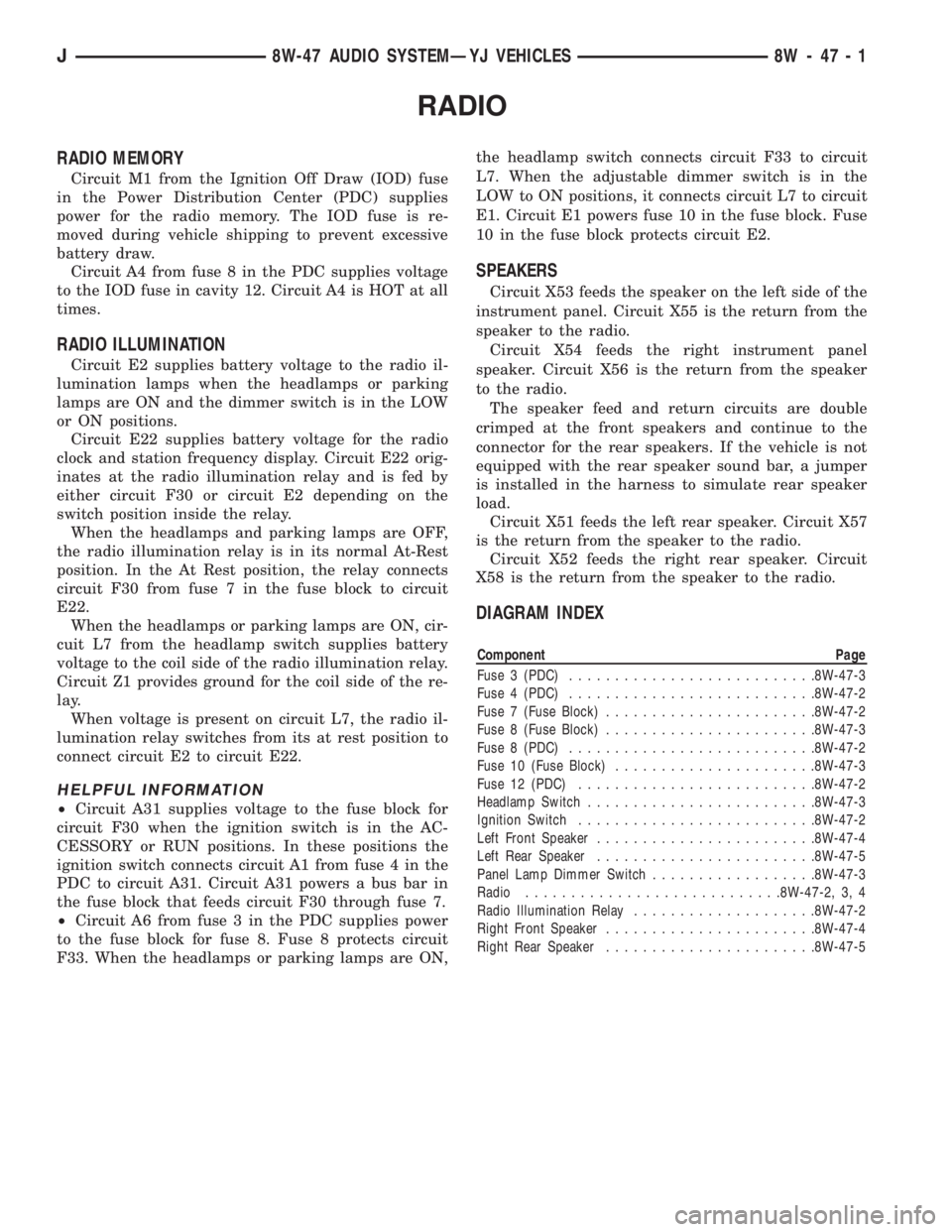
RADIO MEMORY
Circuit M1 from the Ignition Off Draw (IOD) fuse
in the Power Distribution Center (PDC) supplies
power for the radio memory. The IOD fuse is re-
moved during vehicle shipping to prevent excessive
battery draw.
Circuit A4 from fuse 8 in the PDC supplies voltage
to the IOD fuse in cavity 12. Circuit A4 is HOT at all
times.
RADIO ILLUMINATION
Circuit E2 supplies battery voltage to the radio il-
lumination lamps when the headlamps or parking
lamps are ON and the dimmer switch is in the LOW
or ON positions.
Circuit E22 supplies battery voltage for the radio
clock and station frequency display. Circuit E22 orig-
inates at the radio illumination relay and is fed by
either circuit F30 or circuit E2 depending on the
switch position inside the relay.
When the headlamps and parking lamps are OFF,
the radio illumination relay is in its normal At-Rest
position. In the At Rest position, the relay connects
circuit F30 from fuse 7 in the fuse block to circuit
E22.
When the headlamps or parking lamps are ON, cir-
cuit L7 from the headlamp switch supplies battery
voltage to the coil side of the radio illumination relay.
Circuit Z1 provides ground for the coil side of the re-
lay.
When voltage is present on circuit L7, the radio il-
lumination relay switches from its at rest position to
connect circuit E2 to circuit E22.
HELPFUL INFORMATION
²Circuit A31 supplies voltage to the fuse block for
circuit F30 when the ignition switch is in the AC-
CESSORY or RUN positions. In these positions the
ignition switch connects circuit A1 from fuse 4 in the
PDC to circuit A31. Circuit A31 powers a bus bar in
the fuse block that feeds circuit F30 through fuse 7.
²Circuit A6 from fuse 3 in the PDC supplies power
to the fuse block for fuse 8. Fuse 8 protects circuit
F33. When the headlamps or parking lamps are ON,the headlamp switch connects circuit F33 to circuit
L7. When the adjustable dimmer switch is in the
LOW to ON positions, it connects circuit L7 to circuit
E1. Circuit E1 powers fuse 10 in the fuse block. Fuse
10 in the fuse block protects circuit E2.
SPEAKERS
Circuit X53 feeds the speaker on the left side of the
instrument panel. Circuit X55 is the return from the
speaker to the radio.
Circuit X54 feeds the right instrument panel
speaker. Circuit X56 is the return from the speaker
to the radio.
The speaker feed and return circuits are double
crimped at the front speakers and continue to the
connector for the rear speakers. If the vehicle is not
equipped with the rear speaker sound bar, a jumper
is installed in the harness to simulate rear speaker
load.
Circuit X51 feeds the left rear speaker. Circuit X57
is the return from the speaker to the radio.
Circuit X52 feeds the right rear speaker. Circuit
X58 is the return from the speaker to the radio.
DIAGRAM INDEX
Component Page
Fuse 3 (PDC)...........................8W-47-3
Fuse 4 (PDC)...........................8W-47-2
Fuse 7 (Fuse Block).......................8W-47-2
Fuse 8 (Fuse Block).......................8W-47-3
Fuse 8 (PDC)...........................8W-47-2
Fuse 10 (Fuse Block)......................8W-47-3
Fuse 12 (PDC)..........................8W-47-2
Headlamp Switch.........................8W-47-3
Ignition Switch..........................8W-47-2
Left Front Speaker........................8W-47-4
Left Rear Speaker........................8W-47-5
Panel Lamp Dimmer Switch..................8W-47-3
Radio............................8W-47-2, 3, 4
Radio Illumination Relay....................8W-47-2
Right Front Speaker.......................8W-47-4
Right Rear Speaker.......................8W-47-5
J8W-47 AUDIO SYSTEMÐYJ VEHICLES 8W - 47 - 1
Page 1186 of 2158

HEATED REAR WINDOW
HEATED REAR WINDOW
The heated rear window relay supplies power to
heated rear window grid. When the operator presses
the heated rear window switch, the contacts inside
the switch momentarily close and circuit C16 con-
nects the relay timer to ground on circuit Z1. This
causes the relay to change state and complete a cir-
cuit to energize the coil side of the relay and start
the relay timer. Circuit G5 from fuse 9 in the fuse
block supplies voltage to the coil side of the relay.
Circuit Z1 provides ground for the relay.
When the heated rear window relay energizes, the
contacts inside the relay close and connect circuit
F32 to circuit C15. Fuse 3 in the fuse block protects
circuit F32.
Circuit C15 is double crimped at the heated rear
window relay. One branch of circuit C15 powers the
indicator lamp in the heated rear window switch.
The other branch of circuit C15 powers the heated
rear window grid. Circuit Z1 provides ground for the
heated rear window grid.
At the rear window grid, circuits C15 and Z1 pass
through lift gate support struts.
HELPFUL INFORMATION
²When the ignition switch is in the START or RUN
positions, it connects circuit A1 from fuse 4 in the
Power Distribution Center (PDC) to circuit A21. Cir-
cuit A21 supplies battery voltage to the fuse block
bus bar that powers circuit G5 through the fuse in
cavity 9.
²Circuit A6 from PDC fuse 3 supplies battery volt-
age to the fuse block bus bar that feeds fuse 3 and
circuit F32. Check fuse 3 in the PDC and fuse 3 in
the fuse block.
²Check for broken grid lines on the window.
²Check for a broken bus bar or disconnected leads
at the rear window.
²Check for a good ground.
DIAGRAM INDEX
Component Page
Fuse 3 (PDC)...........................8W-48-2
Fuse 4 (PDC)...........................8W-48-2
Fuse 6 (Fuse Block).......................8W-48-2
Fuse 9 (Fuse Block).......................8W-48-2
Heated Rear Window Relay..................8W-48-2
Heated Rear Window Grid...................8W-48-3
Heated Rear Window Switch.................8W-48-3
J8W-48 HEATED REAR WINDOWÐYJ VEHICLES 8W - 48 - 1
Page 1190 of 2158
FRONT LIGHTING
INDEX
page page
Daytime Running Lamp (DRL) ModuleÐCanadian
Vehicles Only........................... 2
Diagram Index............................ 2
Fog Lamps............................... 1Headlamps............................... 1
Parking Lamps............................ 1
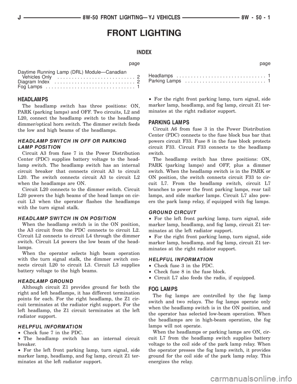
HEADLAMPS
The headlamp switch has three positions: ON,
PARK (parking lamps) and OFF. Two circuits, L2 and
L20, connect the headlamp switch to the headlamp
dimmer/optical horn switch. The dimmer switch feeds
the low and high beams of the headlamps.
HEADLAMP SWITCH IN OFF OR PARKING
LAMP POSITION
Circuit A3 from fuse 7 in the Power Distribution
Center (PDC) supplies battery voltage to the head-
lamp switch. The headlamp switch has an internal
circuit breaker that connects circuit A3 to circuit
L20. The switch connects circuit A3 to circuit L2
when the headlamps are ON.
Circuit L20 connects to the dimmer switch. Circuit
L20 powers the high beams of the head lamps on cir-
cuit L3 when the operator flashes the headlamps
with the turn signal stalk.
HEADLAMP SWITCH IN ON POSITION
When the headlamp switch is in the ON position,
the A3 circuit from the PDC connects to circuit L2.
Circuit L2 connects to circuit L4 through the dimmer
switch. Circuit L4 powers the low beam of the head-
lamps.
When the operator selects high beam operation
with the turn signal stalk, the dimmer switch con-
nects circuit L20 to circuit L3. Circuit L3 supplies
battery voltage to the high beams.
HEADLAMP GROUND
Although circuit Z1 provides ground for both the
right and left headlamps, it has different termination
points for each. For the right headlamp, the Z1 cir-
cuit terminates at the radiator right support. For the
left headlamp, the Z1 circuit terminates at the left
radiator support.
HELPFUL INFORMATION
²Check fuse 7 in the PDC.
²The headlamp switch has an internal circuit
breaker.
²For the left front parking lamp, turn signal, side
marker lamp, headlamp, and fog lamp, circuit Z1 ter-
minates at the left radiator support.²For the right front parking lamp, turn signal, side
marker lamp, headlamp, and fog lamp, circuit Z1 ter-
minates at the right radiator support.
PARKING LAMPS
Circuit A6 from fuse 3 in the Power Distribution
Center (PDC) connects to the fuse block bus bar that
powers circuit F33. Fuse 8 in the fuse block protects
circuit F33. Circuit F33 connects to the headlamp
switch.
The headlamp switch has three positions: ON,
PARK (parking lamps) and OFF, plus a dimmer
switch. When the headlamp switch is in the PARK or
ON position, the switch connects circuit F33 to cir-
cuit L7. From the headlamp switch, circuit L7
branches to power the front parking lamps, rear tail
lamps, and side marker lamps. Circuit L7 also pow-
ers the park lamp relay, if equipped with fog lamps.
GROUND CIRCUIT
²For the left front parking lamp, turn signal, side
marker lamp, headlamp, and fog lamp, circuit Z1 ter-
minates at the left radiator support.
²For the right front parking lamp, turn signal, side
marker lamp, headlamp, and fog lamp, circuit Z1 ter-
minates at the right radiator support.
HELPFUL INFORMATION
²Check fuse 3 in the PDC.
²Check fuse 8 in the fuse block.
²Circuit L7 also feeds the radio, if equipped.
FOG LAMPS
The fog lamps are controlled by the fog lamp
switch and two relays. The fog lamps operate only
when the headlamp switch is in the ON position, and
the operator has selected low-beam operation. When
the headlamps are in high-beam operation, the fog
lamps will not operate.
When the headlamps or parking lamps are ON, cir-
cuit L7 from the headlamp switch supplies battery
voltage to the coil side of the park lamp relay. When
the operator presses the fog lamp switch, it provides
ground for the coil side of the park lamp relay. This
energizes the relay.
J8W-50 FRONT LIGHTINGÐYJ VEHICLES 8W - 50 - 1
Page 1191 of 2158
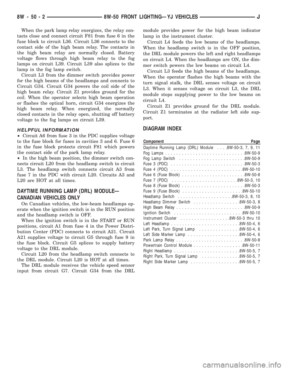
When the park lamp relay energizes, the relay con-
tacts close and connect circuit F81 from fuse 6 in the
fuse block to circuit L36. Circuit L36 connects to the
contact side of the high beam relay. The contacts in
the high beam relay are normally closed. Battery
voltage flows through high beam relay to the fog
lamps on circuit L39. Circuit L39 also splices to the
lamp in the fog lamp switch.
Circuit L3 from the dimmer switch provides power
for the high beams of the headlamps and connects to
Circuit G34. Circuit G34 powers the coil side of the
high beam relay. Circuit Z1 provides ground for the
coil. When the operator selects high beam operation
or flashes the optical horn, circuit G34 energizes the
high beam relay. When energized, the normally
closed contacts in the relay open, shutting off battery
voltage to the fog lamps on circuit L39.
HELPFUL INFORMATION
²Circuit A6 from fuse 3 in the PDC supplies voltage
to the fuse block for fuses in cavities 3 and 6. Fuse 6
in the fuse block protects circuit F81 which powers
the contact side of the park lamp relay.
²In the high beam position, the dimmer switch con-
nects circuit L20 from the headlamp switch to circuit
L3. The headlamp switch connects circuit A3 from
fuse 7 in the PDC with circuit L20. Circuits A3 and
L20 are HOT at all times.
DAYTIME RUNNING LAMP (DRL) MODULEÐ
CANADIAN VEHICLES ONLY
On Canadian vehicles, the low-beam headlamps op-
erate when the ignition switch is in the RUN position
and the headlamp switch is OFF.
When the ignition switch is in the START or RUN
positions, circuit A1 from fuse 4 in the Power Distri-
bution Center (PDC) connects to circuit A21. Circuit
A21 supplies voltage to circuit G5 through fuse 9 in
the fuse block. Circuit G5 splices to supply battery
voltage to the DRL module.
Circuit L20 from the headlamp switch connects to
the DRL module. Circuit L20 is HOT at all times.
The DRL module receives the vehicle speed sensor
input from circuit G7. Circuit G34 from the DRLmodule provides power for the high beam indicator
lamp in the instrument cluster.
Circuit L4 feeds the low beams of the headlamps.
When the headlamp switch is in the OFF position,
the DRL module powers the left and right headlamps
on circuit L4. When the headlamps are ON, the dim-
mer switch powers the low beams on circuit L4.
Circuit L3 feeds the high beams of the headlamps.
When the operator flashes the high beams with the
turn signal stalk, the DRL senses voltage on circuit
L3. When it senses voltage on circuit L3, the DRL
module stops supplying power to the low beams on
circuit L4.
Circuit Z1 provides ground for the DRL module.
Circuit Z1 terminates at the radiator left side sup-
port.
DIAGRAM INDEX
Component Page
Daytime Running Lamp (DRL) Module. . . .8W-50-3, 7, 9, 11
Fog Lamps.............................8W-50-9
Fog Lamp Switch........................8W-50-9
Fuse 3 (PDC)...........................8W-50-3
Fuse 4 (PDC)..........................8W-50-10
Fuse 6 (Fuse Block).......................8W-50-8
Fuse 7 (PDC)........................8W-50-3, 10
Fuse 8 (Fuse Block).......................8W-50-3
Fuse 9 (Fuse Block)......................8W-50-10
Headlamp Switch....................8W-50-3, 8, 10
Headlamp Dimmer Switch.................8W-50-3, 8
High Beam Relay.........................8W-50-9
Ignition Switch.........................8W-50-10
Instrument Cluster..................8W-50-3 thru 10
Left Headlamp.........................8W-50-4, 6
Left Park, Turn Signal Lamp...............8W-50-4, 6
Left Side Marker Lamp...................8W-50-4, 6
Park Lamp Relay.........................8W-50-8
Powertrain Control Module..................8W-50-11
Right Headlamp........................8W-50-5, 7
Right Park, Turn Signal Lamp..............8W-50-5, 7
Right Side Marker Lamp..................8W-50-5, 7
8W - 50 - 2 8W-50 FRONT LIGHTINGÐYJ VEHICLESJ
Page 1202 of 2158
REAR LIGHTING
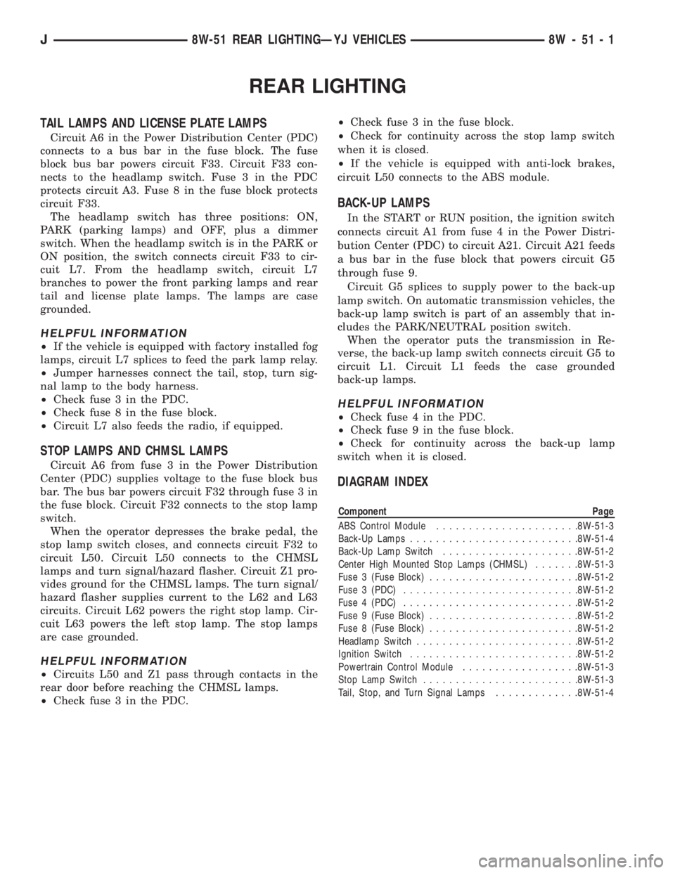
TAIL LAMPS AND LICENSE PLATE LAMPS
Circuit A6 in the Power Distribution Center (PDC)
connects to a bus bar in the fuse block. The fuse
block bus bar powers circuit F33. Circuit F33 con-
nects to the headlamp switch. Fuse 3 in the PDC
protects circuit A3. Fuse 8 in the fuse block protects
circuit F33.
The headlamp switch has three positions: ON,
PARK (parking lamps) and OFF, plus a dimmer
switch. When the headlamp switch is in the PARK or
ON position, the switch connects circuit F33 to cir-
cuit L7. From the headlamp switch, circuit L7
branches to power the front parking lamps and rear
tail and license plate lamps. The lamps are case
grounded.
HELPFUL INFORMATION
²If the vehicle is equipped with factory installed fog
lamps, circuit L7 splices to feed the park lamp relay.
²Jumper harnesses connect the tail, stop, turn sig-
nal lamp to the body harness.
²Check fuse 3 in the PDC.
²Check fuse 8 in the fuse block.
²Circuit L7 also feeds the radio, if equipped.
STOP LAMPS AND CHMSL LAMPS
Circuit A6 from fuse 3 in the Power Distribution
Center (PDC) supplies voltage to the fuse block bus
bar. The bus bar powers circuit F32 through fuse 3 in
the fuse block. Circuit F32 connects to the stop lamp
switch.
When the operator depresses the brake pedal, the
stop lamp switch closes, and connects circuit F32 to
circuit L50. Circuit L50 connects to the CHMSL
lamps and turn signal/hazard flasher. Circuit Z1 pro-
vides ground for the CHMSL lamps. The turn signal/
hazard flasher supplies current to the L62 and L63
circuits. Circuit L62 powers the right stop lamp. Cir-
cuit L63 powers the left stop lamp. The stop lamps
are case grounded.
HELPFUL INFORMATION
²Circuits L50 and Z1 pass through contacts in the
rear door before reaching the CHMSL lamps.
²Check fuse 3 in the PDC.²Check fuse 3 in the fuse block.
²Check for continuity across the stop lamp switch
when it is closed.
²If the vehicle is equipped with anti-lock brakes,
circuit L50 connects to the ABS module.
BACK-UP LAMPS
In the START or RUN position, the ignition switch
connects circuit A1 from fuse 4 in the Power Distri-
bution Center (PDC) to circuit A21. Circuit A21 feeds
a bus bar in the fuse block that powers circuit G5
through fuse 9.
Circuit G5 splices to supply power to the back-up
lamp switch. On automatic transmission vehicles, the
back-up lamp switch is part of an assembly that in-
cludes the PARK/NEUTRAL position switch.
When the operator puts the transmission in Re-
verse, the back-up lamp switch connects circuit G5 to
circuit L1. Circuit L1 feeds the case grounded
back-up lamps.
HELPFUL INFORMATION
²Check fuse 4 in the PDC.
²Check fuse 9 in the fuse block.
²Check for continuity across the back-up lamp
switch when it is closed.
DIAGRAM INDEX
Component Page
ABS Control Module......................8W-51-3
Back-Up Lamps..........................8W-51-4
Back-Up Lamp Switch.....................8W-51-2
Center High Mounted Stop Lamps (CHMSL).......8W-51-3
Fuse 3 (Fuse Block).......................8W-51-2
Fuse 3 (PDC)...........................8W-51-2
Fuse 4 (PDC)...........................8W-51-2
Fuse 9 (Fuse Block).......................8W-51-2
Fuse 8 (Fuse Block).......................8W-51-2
Headlamp Switch.........................8W-51-2
Ignition Switch..........................8W-51-2
Powertrain Control Module..................8W-51-3
Stop Lamp Switch........................8W-51-3
Tail, Stop, and Turn Signal Lamps.............8W-51-4
J8W-51 REAR LIGHTINGÐYJ VEHICLES 8W - 51 - 1
Page 1206 of 2158
TURN SIGNALS
TURN SIGNALS
In the ACCESSORY or RUN position, the ignition
switch connects circuit A1 from fuse 4 in the Power
Distribution Center (PDC) to circuit A31. Circuit A31
feeds circuit L5 through fuse 4 in the fuse block.
Circuit L5 powers the turn signal flasher. Circuit
L6 from the flasher connects to the turn signal/haz-
ard flasher switch which supplies current to the turn
signals. The switch connects to the turn signal and
side marker lamps on circuits L60, L61, L62 and
L63.
RIGHT TURN SIGNAL
When the operator selects the right turn signal, the
turn signal/hazard flasher switch connects power
from circuit L6 to circuits L60 and L62. Circuit L62
feeds the right rear turn signal/hazard flasher/stop
lamp.
Circuit L60 feeds the right front turn signal/hazard
flasher lamp and side marker lamp. Circuit L60 also
splices to power the turn signal indicator lamp on the
instrument cluster.
LEFT TURN SIGNAL
When the operator selects the left turn signal, the
turn signal/hazard flasher switch connects power
from circuit L6 to circuits L61 and L63. Circuit L63
feeds the left rear turn signal/hazard flasher/stop
lamp.
Circuit L61 feeds the left front turn signal/hazard
flasher lamp and side marker lamp. Circuit L61 also
splices to power the turn signal indicator lamp on the
instrument cluster.
GROUND CIRCUIT
Circuit Z1 provides a ground for the left front park
and turn signal lamp, side marker lamp and head
lamp. The grounding point for circuit Z1 is the radi-
ator left support.
Circuit Z1 provides a ground for the right front
park and turn signal lamp, side marker lamp and
head lamp. The grounding point for circuit Z1 is the
radiator right support.
HELPFUL INFORMATION
²Check fuse 4 in the PDC.
²Check fuse 4 in the fuse block.
HAZARD FLASHERS
Circuit L9 from fuse 5 in the Power Distribution
Center (PDC) supplies power to the hazard flasher.
Circuit L19 from the flasher connects to the turn sig-
nal/hazard flasher switch.When the operator presses the hazard flasher but-
ton, the turn signal/hazard flasher switch connects
circuit L19 to circuits L60, L61, L62, and L63. Cir-
cuit L62 powers the right rear turn signal/stop/haz-
ard lamp. Circuit L63 powers the left rear turn
signal/stop/hazard lamp. Circuit L60 powers the right
front indicator lamp. Circuit L61 powers the left
front lamp.
Circuit L60 also splices to feed the instrument clus-
ter right indicator lamp. Circuit L61 splices to feed
the instrument cluster left indicator lamp.
GROUND CIRCUIT
The rear turn signal/stop/hazard lamps are case
grounded.
Circuit Z1 provides a ground for the left front park
and turn signal lamp, side marker lamp and head
lamp. The grounding point for circuit Z1 is the radi-
ator left support.
Circuit Z1 provides a ground for the right left park
and turn signal lamp, side marker lamp and head
lamp. The grounding point for circuit Z1 is the radi-
ator right support.
HELPFUL INFORMATION
Check fuse 5 in the PDC.
DIAGRAM INDEX
Component Page
ABS Control Module......................8W-52-2
Fuse 3 (Fuse Block).......................8W-52-2
Fuse 3 (PDC)...........................8W-52-2
Fuse 4 (Fuse Block).......................8W-52-2
Fuse 4 (PDC)...........................8W-52-2
Fuse 5 (PDC)...........................8W-52-2
Hazard Flasher..........................8W-52-2
Ignition Switch..........................8W-52-2
Instrument Cluster Turn Signal Lamps...........8W-52-3
Stop Lamp Switch........................8W-52-2
Turn Signal Flasher.......................8W-52-2
Turn Signal/Hazard Flasher Switch..............8W-52-3
J8W-52 TURN SIGNALSÐYJ VEHICLES 8W - 52 - 1
Page 1210 of 2158
WIPERS
INDEX
page page
Diagram Index............................ 2
Rear Wiper System......................... 1WipersÐIntermittent........................ 1
WipersÐStandard.......................... 1
WIPERSÐSTANDARD
A circuit breaker in the fuse block powers the stan-
dard wiper system. The standard wiper system oper-
ates at either LOW or HIGH speeds.
In the ACCESSORY or RUN position, the ignition
switch connects circuit A1 from fuse 4 in the Power
Distribution Center (PDC) with circuit A31. Circuit
A31 supplies voltage to circuit V6 through the circuit
breaker in cavity 11 of the fuse block.
Circuit V6 is double crimped at the circuit breaker
and supplies power to the wiper switch and the park
switch in the wiper motor. Circuit Z1 provides
ground for the wiper motor and switch.
When the operator moves the wiper switch to the
LOW position, battery voltage passes through the
switch to circuit V3. Circuit V3 feeds the wiper motor
low speed brushes. If the operator selects wiper
HIGH speed operation, the wiper switch passes cur-
rent to circuit V4. Circuit V4 feeds the wiper motor
high speed brushes.
As the windshield wiper motor turns, the park
switch, internal to the motor, moves from its DOWN
position to the UP position. When the wiper switch is
turned OFF, the V5 circuit prevents the wipers from
stopping in any position but park.
The windshield washer uses a pump motor located
inside the windshield washer fluid reservoir. When
the washer switch is pressed, power is supplied
through the wiper switch to the pump motor on cir-
cuit V10. Circuit Z1 provide ground for the pump mo-
tor.
WIPERSÐINTERMITTENT
A circuit breaker in the fuse block powers the in-
termittent wiper system. The wiper system operates
at either LOW, HIGH, or DELAY speeds.
In the ACCESSORY or RUN position, the ignition
switch connects circuit A1 from fuse 4 in the Power
Distribution Center (PDC) with circuit A31. Circuit
A31 supplies voltage to circuit V6 through the circuit
breaker in cavity 11 of the fuse block.
Circuit V6 is double crimped at the circuit breaker
and supplies power to the wiper switch and the park
switch in the wiper motor. Circuit Z1 provides
ground for the wiper motor and switch.When the operator moves the wiper switch to the
LOW position, battery voltage passes through the
switch to circuit V3. Circuit V3 feeds the wiper motor
low speed brushes. If the operator selects wiper
HIGH speed operation, the wiper switch passes cur-
rent to circuit V4. Circuit V4 feeds the wiper motor
high speed brushes.
The DELAY portion of the wiper switch contains a
variable resistor. The variable resistor connects to
the intermittent wiper module through the wiper
switch harness. The amount of delay selected by the
operator determines the voltage drop through the re-
sistor and the voltage level received by the intermit-
tent wiper module.
After the intermittent wiper control module deter-
mines the amount of delay selected, it cycles the wip-
ers by periodically energizing circuit V3. Circuit V3
powers the wiper motor low speed brushes.
As the windshield wiper motor turns, the park
switch, internal to the motor, moves from its DOWN
position to the UP position. When the wiper switch is
turned OFF, the V5 circuit prevents the wipers from
stopping in any position but park.
The windshield washer uses a pump motor located
inside the windshield washer fluid reservoir. When
the washer switch is pressed, power is supplied
through the wiper switch to the pump motor on cir-
cuit V10. Circuit Z1 provides ground for the pump
motor.
REAR WIPER SYSTEM
In the RUN position, the ignition switch connects
circuit A1 from fuse 4 in the Power Distribution Cen-
ter (PDC) with circuit A22. Circuit A22 connects to a
fuse block in the bus bar that powers circuit V23
through the fuse in cavity 1.
Circuit V23 supplies power to the park switch in
the rear wiper motor. Also, circuit V22 is crimped to
circuit V23 at the rear wiper motor connector. Circuit
V22 supplies current to the rear wiper switch.
In the WIPE or WASH positions, the rear wiper
switch supplies voltage to the wiper motor on circuit
V13. Circuit Z1 provides ground for the wiper motor.
J8W-53 WIPERSÐYJ VEHICLES 8W - 53 - 1
Page 1211 of 2158
The rear windshield washer uses a pump motor lo-
cated inside the windshield washer fluid reservoir.
When the rear wiper switch is pressed, power is sup-
plied through the wiper switch to the pump motor on
circuit V20. Circuit Z1 provides ground for the pump
motor.DIAGRAM INDEX
Component Page
Circuit Breaker (Fuse Block Cavity 11).........8W-53-4, 5
Fuse 4 (PDC).......................8W-53-3, 4, 5,
Fuse 4 (Fuse Block).....................8W-53-4, 5
Fuse 7 (Fuse Block).....................8W-53-4, 5
Ignition Switch......................8W-53-3, 4, 5
Intermittent Wiper Control Module.............8W-53-5
Intermittent Wiper Switch...................8W-53-5
Rear Windshield Washer Pump Motor...........8W-53-3
Rear Wiper Motor........................8W-53-3
Standard Wiper Switch.....................8W-53-4
Windshield Washer Pump Motor.............8W-53-4, 5
Wiper Motor..........................8W-53-4, 5
8W - 53 - 2 8W-53 WIPERSÐYJ VEHICLESJ