1995 JEEP XJ Brake lamp
[x] Cancel search: Brake lampPage 1461 of 2158
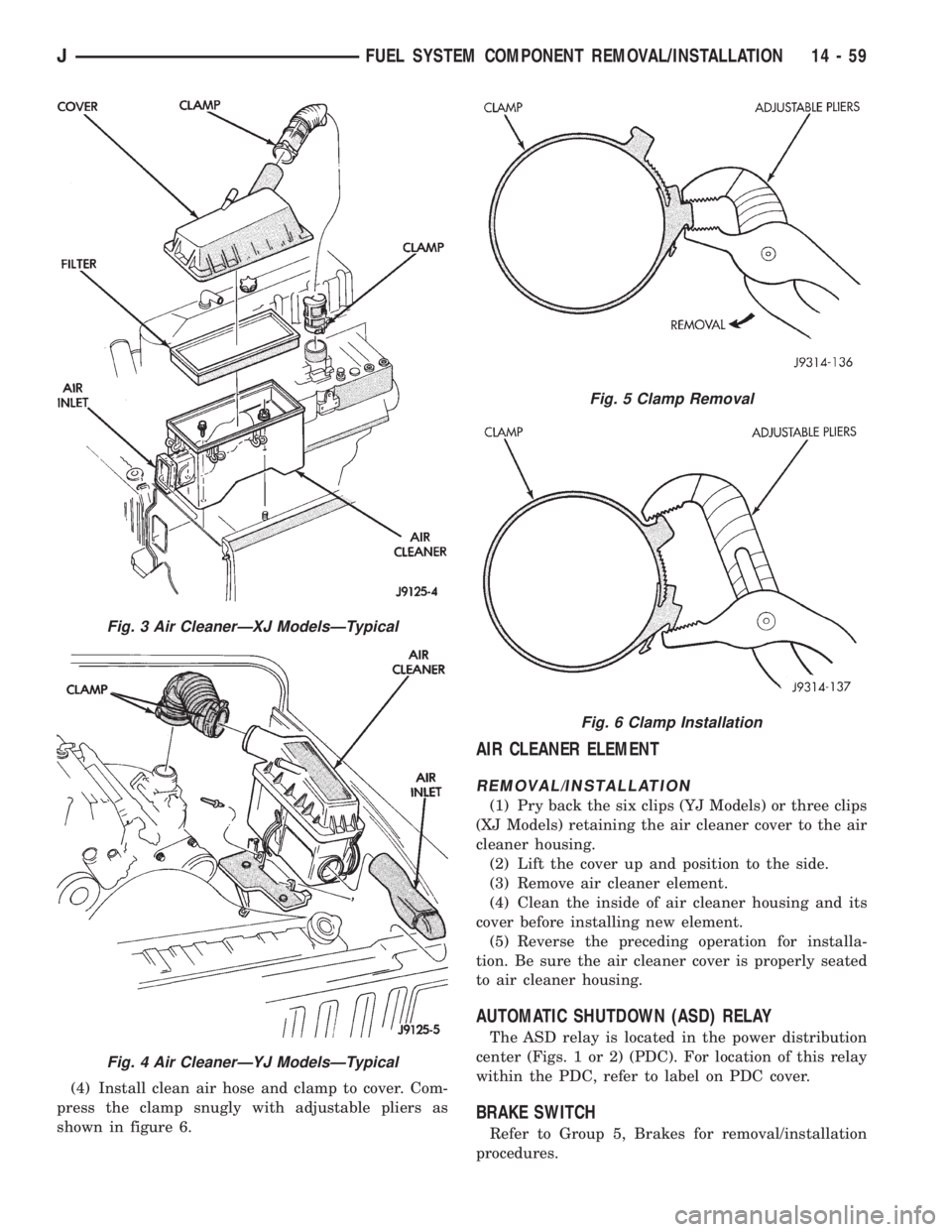
(4) Install clean air hose and clamp to cover. Com-
press the clamp snugly with adjustable pliers as
shown in figure 6.
AIR CLEANER ELEMENT
REMOVAL/INSTALLATION
(1) Pry back the six clips (YJ Models) or three clips
(XJ Models) retaining the air cleaner cover to the air
cleaner housing.
(2) Lift the cover up and position to the side.
(3) Remove air cleaner element.
(4) Clean the inside of air cleaner housing and its
cover before installing new element.
(5) Reverse the preceding operation for installa-
tion. Be sure the air cleaner cover is properly seated
to air cleaner housing.
AUTOMATIC SHUTDOWN (ASD) RELAY
The ASD relay is located in the power distribution
center (Figs. 1 or 2) (PDC). For location of this relay
within the PDC, refer to label on PDC cover.
BRAKE SWITCH
Refer to Group 5, Brakes for removal/installation
procedures.
Fig. 3 Air CleanerÐXJ ModelsÐTypical
Fig. 4 Air CleanerÐYJ ModelsÐTypical
Fig. 5 Clamp Removal
Fig. 6 Clamp Installation
JFUEL SYSTEM COMPONENT REMOVAL/INSTALLATION 14 - 59
Page 1472 of 2158
SERVICE DIAGNOSIS
INDEX
page page
Runout.................................. 4
Unbalance............................... 3Universal Joint Angle Measurement............. 4
Vibration................................. 3
VIBRATION
Tires that are out-of-round or wheels that are un-
balanced will cause a low frequency vibration. Refer
to Group 22, Wheels and Tires for additional infor-
mation.
Brake drums that are unbalanced will cause a
harsh, low frequency vibration. Refer to Group 5,
Brakes for additional information.
Driveline vibration can also result from loose or
damaged engine mounts. Refer to Group 21, Trans-
missions for additional information.
Propeller shaft vibration will increase as the vehi-
cle speed is increased. A vibration that occurs within
a specific speed range is not caused by propeller
shaft unbalance. Defective universal joints or an in-
correct propeller shaft angle are usually the cause.
UNBALANCE
If propeller shaft unbalance is suspected, it can be
verified with the following procedure.
Removing and re-indexing the propeller shaft
180É may eliminate some vibrations.
²Clean all the foreign material from the propeller
shaft and the universal joints.²Inspect the propeller shaft for missing balance
weights, broken welds, and bent areas.If the pro-
peller shaft is bent, it must be replaced.
²Ensure the universal joints are not worn, are prop-
erly installed, and are correctly aligned with the
shaft.
²Check the universal joint clamp screws torque
(1) Raise the vehicle.
(2) Remove the wheel and tires assembly. Install
the wheel lug nuts to retain the brake drums.
(3) Mark and number the shaft six inches from the
yoke end at four positions 90É apart.
(4) Run and accelerate the vehicle until vibration
occurs. Note the intensity and speed the vibration oc-
curred. Stop the engine.
(5) Install a screw clamp at position 1 (Fig. 1).
(6) Start the engine and re-check for vibration. If
there is little or no change in vibration, move the
clamp to one of the other three positions. Repeat the
vibration test.
(7) If there is no difference in vibration at the
other positions, the vibration may not be propshaft
unbalance.
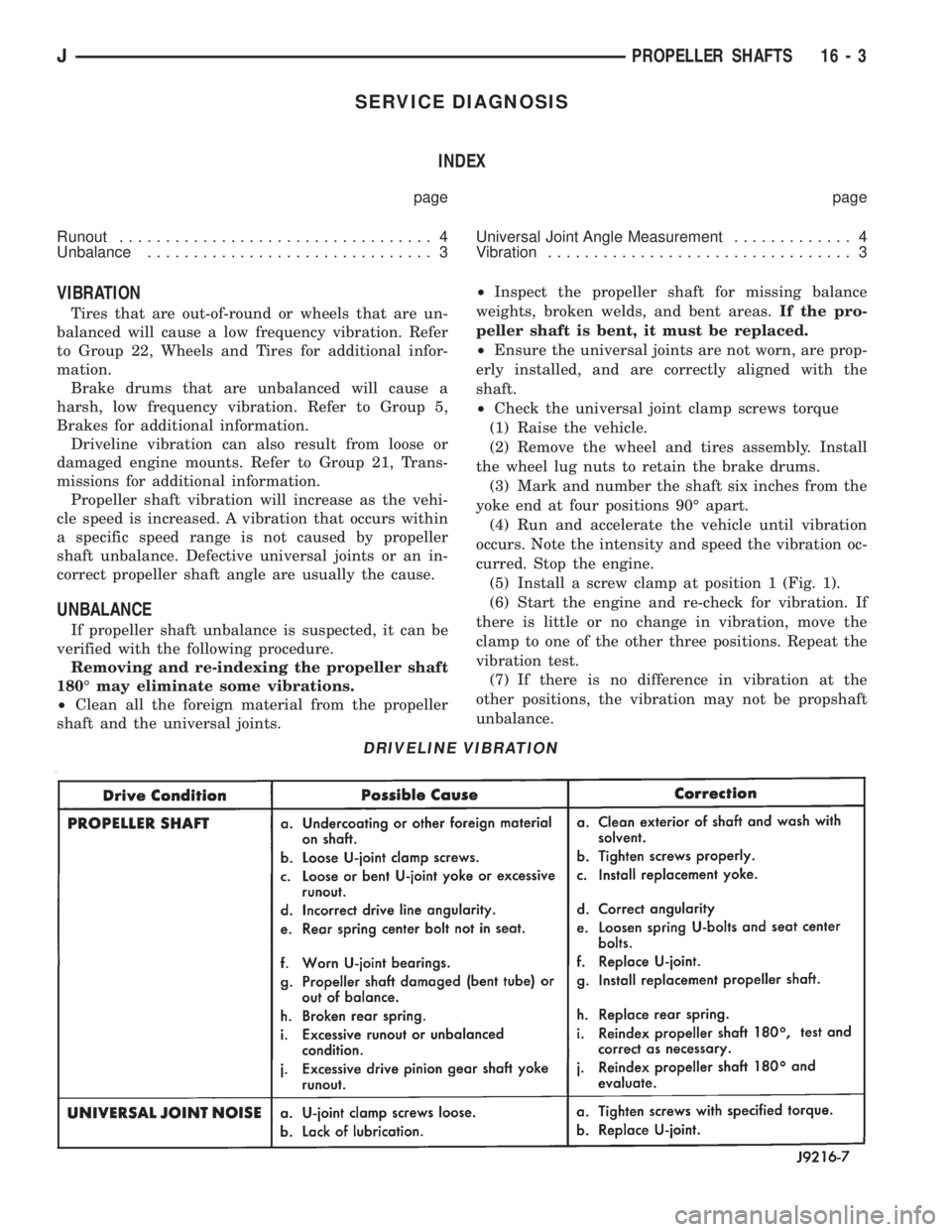
DRIVELINE VIBRATION
JPROPELLER SHAFTS 16 - 3
Page 1662 of 2158
(c) Vehicle is used for trailer towing or heavy
load hauling.
FLUID/FILTER REPLACEMENT PROCEDURE
(1) Raise vehicle.
(2) Remove oil pan and drain fluid.
(3) Clean oil pan and pan magnet. Then clean re-
maining gasket material from gasket surface of
transmission case.
(4) Remove fluid filter screws and remove filter.
(5) Position new filter on valve body and install fil-
ter screws. Tighten screws to 4 Nzm (35 in. lbs.)
torque.
(6) Adjust rear band at this time if required.
(7) Position new gasket on oil pan and install pan
on transmission. Tighten pan bolts to 150 in. lbs. (17
Nzm) torque.
(8) Adjust front band at this time if required.
(9) Lower vehicle and refill transmission with Mo-
par ATF Plus, type 7176 fluid.
REFILLING AFTER OVERHAUL OR FLUID/FILTER
CHANGE
The most effective way to avoid overfilling after a
fluid change or overhaul is as follows:
(1) Remove dipstick and insert clean funnel in
transmission fill tube.
(2) Add following initial quantity of Mopar ATF
Plus to transmission:
(a) If only fluid and filter were changed, add3
pints (1-1/2 quarts)of ATF Plus to transmission.
(b) If transmission was completely overhauled
and torque converter was replaced or drained, add
10 pints (5 quarts)of ATF Plus to transmission.
(3) Apply parking brakes.
(4) Start and run engine at normal curb idle speed.
(5) Apply service brakes, shift transmission
through all gear ranges then back to Neutral, and
leave engine running at curb idle speed.
(6) Remove funnel, insert dipstick and check fluid
level. Add only enough fluid to bring level toMIN
dot mark on dipstick.
(7) Drive vehicle until transmission fluid is at nor-
mal operating temperature. Then recheck fluid level
as described in next step.
(8) Leave engine running at curb idle speed, shift
into Neutral, and check fluid level again. This time,
add just enough fluid to bring level up toMAX ar-
row mark but do not overfill.
(9) When fluid level is correct, shut engine off, re-
lease park brake, remove funnel, and reseat dipstick
in fill tube.
SHIFT LINKAGE ADJUSTMENT (YJ)
(1) Check linkage adjustment by starting engine in
Park and Neutral.(2) Adjustment is OK if engine starts only in park
and Neutral. Adjustment is incorrect if engine starts
in one but not both positions.
(3) If engine starts in any position other than Park
or Neutral, or if engine will not start at all, park/
neutral position switch may be faulty.
(4) Shift transmission into Park.
(5) Raise vehicle.
(6) Check condition of shift rods, bellcrank,
bellcrank brackets and linkage bushings/grommets
(Fig. 2). Tighten, repair, replace worn, damaged
parts. Do not attempt adjustment if linkage compo-
nents are worn or damaged.
(7) Loosen shift rod trunnion lock bolt or nut. Be
sure upper shift rod slides freely in trunnion (Fig. 2).
Also be sure shift rods and bellcrank rotate freely
and do not bind at any point.
(8) Verify that manual lever is in Park detent (Fig.
2). Move lever all the way rearward to be sure it is in
Park.
(9) Check for positive engagement of park lock by
attempting to rotate propeller shaft. Shaft will not
turn when park pawl is engaged.
(10) Adjust shift rod trunnion to a obtain free pin
fit in bellcrank arm and tighten trunnion lock bolt or
nut. Prevent shift rod from turning while tightening
bolt or nut. Gearshift linkage lash must be elimi-
nated to obtain proper adjustment. Eliminate lash by
pulling downward on shift rod and pressing upward
on bellcrank.
(11) Confirm proper adjustment by starting engine
in Park and Neutral. Engine should start in these
positions only.If engine starts in any position
other than Park or Neutral, adjustment is in-
correct or neutral switch is faulty.
(12) Lower vehicle and verify that steering lock op-
erates correctly.
SHIFT CABLE ADJUSTMENT (XJ)
(1) Shift transmission into Park.
(2) Raise vehicle.
(3) Release cable adjuster clamp to unlock cable
(Figs. 3 and 4). Clamp is at transmission end of ca-
ble.
(4) Unsnap cable from transmission cable bracket.
(5) Move transmission shift lever fully rearward to
Park detent. Lever is on manual valve shaft at driver
side of case.
(6) Verify positive engagement of park lock by at-
tempting to rotate propeller shaft. Shaft will not ro-
tate when park lock is engaged.
(7) Snap cable into cable bracket.
(8) Lock shift cable by pressing cable adjuster
clamp down until it snaps into place.
(9) Check engine starting. Engine should start only
in Park and Neutral.
(10) Lower vehicle.
21 - 100 30RH/32RH IN-VEHICLE SERVICEJ
Page 1667 of 2158
(7) Align valve body and seat it on case. Be sure
manual lever shaft and accumulator spring are prop-
erly seated.
(8) Hold valve body in position and install one or
two attaching bolts to hold valve body in place.
(9) Install remaining valve body bolts. Tighten all
bolts evenly in a diagonal pattern to 12 Nzm (105 in-
lbs) torque.
(10) Install new oil filter and tighten filter screws
to4Nzm (35 in. lbs.) torque.
(11) Connect converter solenoid wire to case con-
nector.
(12) Install manual and throttle levers on throttle
lever shaft. Tighten lever clamp screws and check for
free operation. Shaft and levers must operate freely
without any bind.
(13) Install oil pan and new gasket. Tighten pan
bolts to 17 Nzm (13 ft. lbs.) torque.
(14) Install seal on neutral switch, install switch in
case, and connect switch wires.
(15) Lower vehicle.
(16) Fill transmission with Mopar ATF Plus, Type
7176 fluid.
(17) Adjust gearshift linkage and throttle valve
(kickdown) cable if necessary.
GOVERNOR AND PARK GEAR SERVICE
GOVERNOR/PARK GEAR REMOVAL
(1) Raise vehicle.
(2) Mark both propeller shaft yokes for assembly
reference and disconnect propeller shafts at transfer
case.
(3) Disconnect speed sensor wires and remove
speedometer adapter and sensor.
(4) Position support stand under transmission con-
verter housing.
(5) Remove rear crossmember.
(6) Disconnect parking brake cable at equalizer
and disconnect exhaust components as necessary.
(7) Support transfer case with jack.
(8) Remove bolts attaching transfer case to trans-
mission adapter housing and remove transfer case.
(9) Remove bolts attaching adapter, or extension
housing to transmission and remove adapter/housing.
(10) Loosen but do not remove bolts that attach
governor body to park gear.
(11) Rotate transmission output shaft until gover-
nor weight assembly is accessible. Then remove
E-clip at this end of governor shaft.
(12) Remove governor valve and shaft from gover-
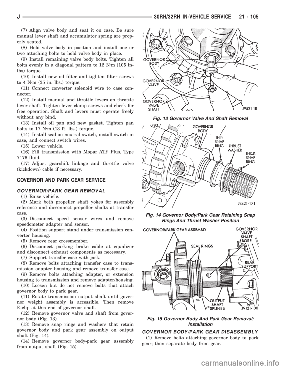
nor body (Fig. 13).
(13) Remove snap rings and washers that retain
governor body and park gear assembly on output
shaft (Fig. 14).
(14) Remove governor body-park gear assembly
from output shaft (Fig. 15).
GOVERNOR BODY/PARK GEAR DISASSEMBLY
(1) Remove bolts attaching governor body to park
gear; then separate body from gear.
Fig. 13 Governor Valve And Shaft Removal
Fig. 14 Governor Body/Park Gear Retaining Snap
Rings And Thrust Washer Position
Fig. 15 Governor Body And Park Gear Removal/
Installation
J30RH/32RH IN-VEHICLE SERVICE 21 - 105
Page 1670 of 2158
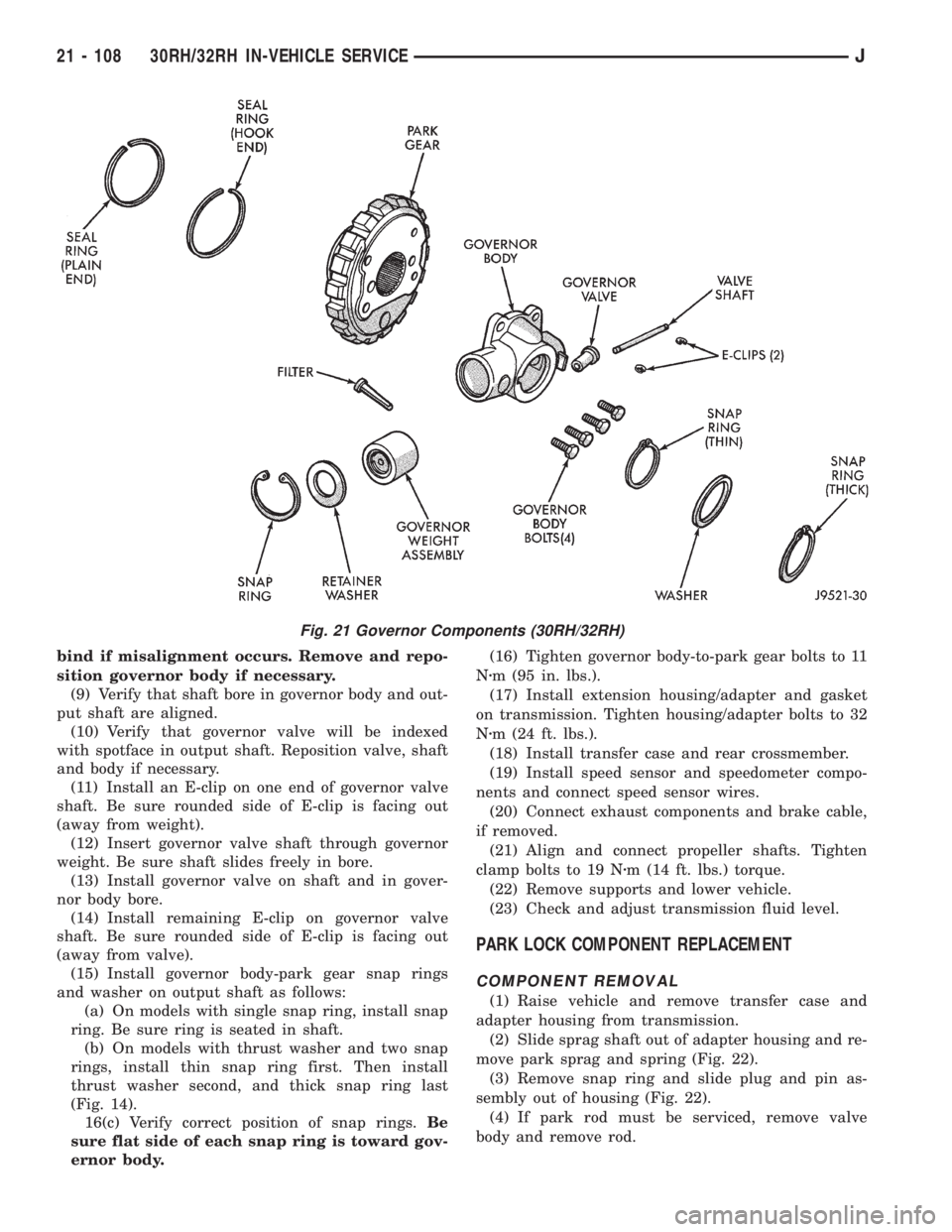
bind if misalignment occurs. Remove and repo-
sition governor body if necessary.
(9) Verify that shaft bore in governor body and out-
put shaft are aligned.
(10) Verify that governor valve will be indexed
with spotface in output shaft. Reposition valve, shaft
and body if necessary.
(11) Install an E-clip on one end of governor valve
shaft. Be sure rounded side of E-clip is facing out
(away from weight).
(12) Insert governor valve shaft through governor
weight. Be sure shaft slides freely in bore.
(13) Install governor valve on shaft and in gover-
nor body bore.
(14) Install remaining E-clip on governor valve
shaft. Be sure rounded side of E-clip is facing out
(away from valve).
(15) Install governor body-park gear snap rings
and washer on output shaft as follows:
(a) On models with single snap ring, install snap
ring. Be sure ring is seated in shaft.
(b) On models with thrust washer and two snap
rings, install thin snap ring first. Then install
thrust washer second, and thick snap ring last
(Fig. 14).
16(c) Verify correct position of snap rings.Be
sure flat side of each snap ring is toward gov-
ernor body.(16) Tighten governor body-to-park gear bolts to 11
Nzm (95 in. lbs.).
(17) Install extension housing/adapter and gasket
on transmission. Tighten housing/adapter bolts to 32
Nzm (24 ft. lbs.).
(18) Install transfer case and rear crossmember.
(19) Install speed sensor and speedometer compo-
nents and connect speed sensor wires.
(20) Connect exhaust components and brake cable,
if removed.
(21) Align and connect propeller shafts. Tighten
clamp bolts to 19 Nzm (14 ft. lbs.) torque.
(22) Remove supports and lower vehicle.
(23) Check and adjust transmission fluid level.
PARK LOCK COMPONENT REPLACEMENT
COMPONENT REMOVAL
(1) Raise vehicle and remove transfer case and
adapter housing from transmission.
(2) Slide sprag shaft out of adapter housing and re-
move park sprag and spring (Fig. 22).
(3) Remove snap ring and slide plug and pin as-
sembly out of housing (Fig. 22).
(4) If park rod must be serviced, remove valve
body and remove rod.
Fig. 21 Governor Components (30RH/32RH)
21 - 108 30RH/32RH IN-VEHICLE SERVICEJ
Page 1763 of 2158
AW-4 TRANSMISSION OVERHAUL
INDEX
page page
Cleaning and Inspection................... 214
Direct Clutch Overhaul.................... 228
First-Reverse Brake Piston and Transmission Case
Overhaul............................. 247
Forward Clutch Overhaul................... 232
Front Planetary Gear Overhaul.............. 237
Manual Valve Shaft Overhaul............... 215
Oil Pump Overhaul....................... 216
Overdrive Planetary Gear and Clutch Overhaul . . 218Overdrive Support Overhaul................ 226
Overhaul Service Tools.................... 201
Rear Planetary, No. 2 One-Way Clutch and Output
Shaft Overhaul......................... 244
Second Brake Overhaul................... 241
Sun Gear and No. 1 One-Way Clutch Overhaul . . 238
Transmission Assembly and Adjustment........ 265
Transmission Disassembly................. 201
Transmission Valve Body Overhaul........... 250
OVERHAUL SERVICE TOOLS
The special tools needed to overhaul the AW-4
transmission are provided in Tool Kit 6294. However,
Pressure Test Port Adapter 7554 is not included in
this kit and must be ordered separately. The over-
haul tool kit and test port adapter are available
through the parts division and dealer special tool
program.
TRANSMISSION DISASSEMBLY
(1) Remove torque converter.
(2) Remove lower half of filler tube if not previ-
ously removed.
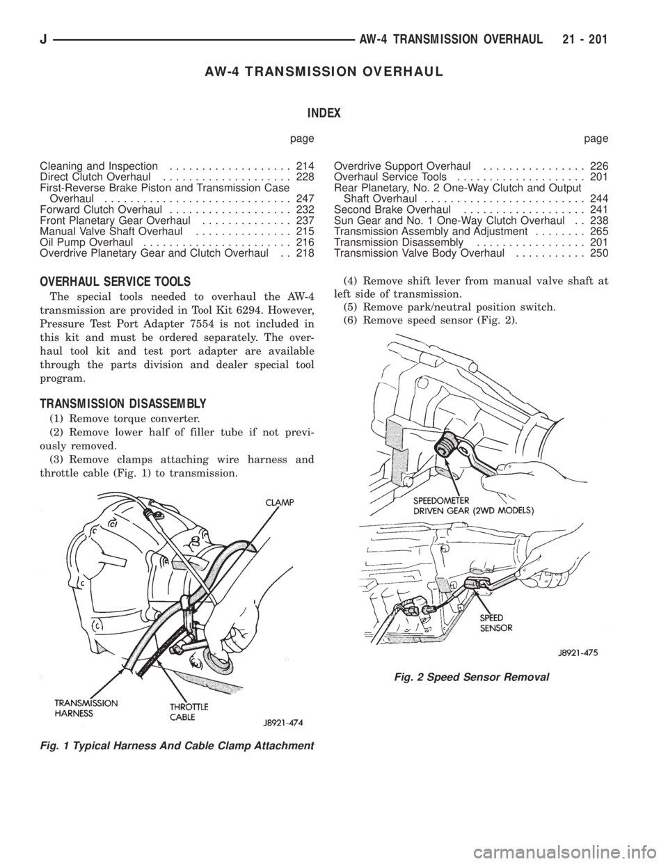
(3) Remove clamps attaching wire harness and
throttle cable (Fig. 1) to transmission.(4) Remove shift lever from manual valve shaft at
left side of transmission.
(5) Remove park/neutral position switch.
(6) Remove speed sensor (Fig. 2).
Fig. 1 Typical Harness And Cable Clamp Attachment
Fig. 2 Speed Sensor Removal
JAW-4 TRANSMISSION OVERHAUL 21 - 201
Page 1998 of 2158
INTERIOR COMPONENTS
INDEX
page page
Assist HandleÐXJ........................ 89
B/C-Pillar and Liftgate Pillar Trim CoversÐXJ.... 88
Bucket Seat Cushion and CoverÐXJ........... 81
Bucket Seat PlatformÐXJ................... 82
Bucket Seatback Cover and FrameÐXJ........ 81
Cargo BarrierÐXJ........................ 101
Cargo LampÐXJ......................... 94
Carpets and Floor MatsÐXJ................. 99
Dome LampÐXJ......................... 93
Front Bucket SeatsÐXJ.................... 81
Front Carpet/MatÐXJ...................... 99
Front Inner Scuff Plate/Cowl Side Trim PanelÐXJ . 86
Front Shoulder Belt/BuckleÐXJ............... 90
Full Floor ConsoleÐXJ..................... 95
HeadlinerÐXJ............................ 92
I/P Ash Receiver Tray LampÐXJ.............. 80
Instrument Cluster BezelÐXJ................ 80
Interior Trim Panels and Scuff PlatesÐXJ....... 84
Jack StorageÐXJ......................... 97
Keyless Entry ReceiverÐXJ................. 93Mini-Console with Floor ShiftÐXJ............. 94
Mini-Floor ConsoleÐXJ..................... 94
Outer Scuff PlatesÐXJ..................... 89
Overhead ConsoleÐXJ..................... 93
Parking Brake Handle CoverÐXJ............. 94
Quarter and Wheelhouse Trim PanelsÐXJ...... 87
Quarter Trim Panel ExtensionÐXJ............. 87
Rear Carpet/MatÐXJ..................... 100
Rear Seat Cushion CoverÐXJ............... 82
Rear Seat CushionÐXJ.................... 82
Rear Seatback CoverÐXJ................... 84
Rear Seatback Latch Striker and BumperÐXJ.... 84
Rear SeatbackÐXJ........................ 83
Rear Shoulder/Lap Belt/BuckleÐXJ............ 91
Sound BarÐXJ........................... 94
Spare Tire/Wheel Holddown and Floor
BracketsÐXJ........................... 98
SunvisorsÐXJ........................... 93
Windshield Side MoldingÐXJ................ 86
INSTRUMENT CLUSTER BEZELÐXJ
REMOVAL
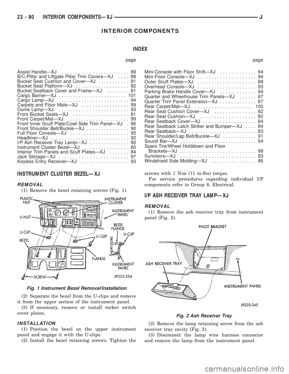
(1) Remove the bezel retaining screws (Fig. 1).
(2) Separate the bezel from the U-clips and remove
it from the upper section of the instrument panel.
(3) If necessary, remove or install rocker switch
cover plates.
INSTALLATION
(1) Position the bezel on the upper instrument
panel and engage it with the U-clips.
(2) Install the bezel retaining screws. Tighten thescrews with 1 Nzm (11 in-lbs) torque.
For service procedures regarding individual I/P
components refer to Group 8, Electrical.
I/P ASH RECEIVER TRAY LAMPÐXJ
REMOVAL
(1) Remove the ash receiver tray from instrument
panel (Fig. 2).
(2) Remove the lamp retaining screw from the ash
receiver tray cavity (Fig. 3).
(3) Disconnect the lamp wire harness connector
and remove the lamp from the instrument panel.
Fig. 1 Instrument Bezel Removal/Installation
Fig. 2 Ash Receiver Tray
23 - 80 INTERIOR COMPONENTSÐXJJ
Page 2012 of 2158
INSTALLATION
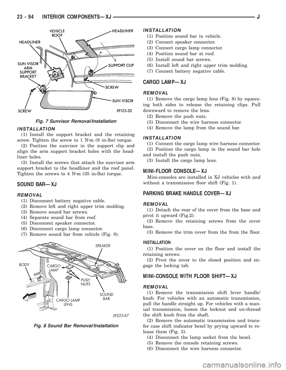
(1) Install the support bracket and the retaining
screw. Tighten the screw to 1 Nzm (9 in-lbs) torque.
(2) Position the sunvisor in the support clip and
align the arm support bracket holes with the head-
liner holes.
(3) Install the screws that attach the sunvisor arm
support bracket to the headliner and the roof panel.
Tighten the screws to 4 Nzm (35 in-lbs) torque.
SOUND BARÐXJ
REMOVAL
(1) Disconnect battery negative cable.
(2) Remove left and right upper trim molding.
(3) Remove sound bar screws.
(4) Separate sound bar from roof.
(5) Disconnect speaker connector.
(6) Disconnect cargo lamp connector.
(7) Remove sound bar from vehicle (Fig. 8).
INSTALLATION
(1) Position sound bar in vehicle.
(2) Connect speaker connecter.
(3) Connect cargo lamp connector.
(4) Position sound bar at roof.
(5) Install sound bar screws.
(6) Install left and right upper trim molding.
(7) Connect battery negative cable.
CARGO LAMPÐXJ
REMOVAL
(1) Remove the cargo lamp lens (Fig. 8) by squeez-
ing both sides to release the retaining clips. Pull
downward to remove the lens.
(2) Remove the push nuts.
(3) Disconnect the wire harness connector.
(4) Remove the lamp from the sound bar.
INSTALLATION
(1) Connect the cargo lamp wire harness connector.
(2) Position the cargo lamp in the sound bar hole
and install the push nuts.
(3) Install the cargo lamp lens.
MINI-FLOOR CONSOLEÐXJ
Mini-consoles are installed in XJ vehicles with and
without a transmission floor shift (Fig. 1).
PARKING BRAKE HANDLE COVERÐXJ
REMOVAL
(1) Detach the rear of the cover from the base and
pivot it upward (Fig.2).
(2) Remove the retaining screws from the cover
base.
(3) Remove the trim cover from the from the floor.
INSTALLATION
(1) Position the cover on the floor and install the
retaining screws.
(2) Pivot the cover to the closed position and en-
gage the locking tab.
MINI-CONSOLE WITH FLOOR SHIFTÐXJ
REMOVAL
(1) Remove the transmission shift lever handle/
knob. For vehicles with an automatic transmission,
pull the handle straight up. For vehicles with a man-
ual transmission, loosen the locknut and un-thread
the shift knob from the shaft.
(2) Remove the automatic transmission and trans-
fer case shift indicator bezel by prying upward to re-
lease them (Fig. 3).
(4) Disconnect the lamp socket from the bezel.
(5) Remove the console retaining screws.
(6) Disconnect the wire harness connector.
Fig. 7 Sunvisor Removal/Installation
Fig. 8 Sound Bar Removal/Installation
23 - 94 INTERIOR COMPONENTSÐXJJ