1995 JEEP CHEROKEE power distribution center
[x] Cancel search: power distribution centerPage 260 of 2198
(5) Be sure that the air conditioner (if equipped) is
turned off.
WARNING: USE EXTREME CAUTION WHEN THE
ENGINE IS OPERATING. DO NOT STAND IN A DI-
RECT LINE WITH THE FAN. DO NOT PUT YOUR
HANDS NEAR THE PULLEYS, BELTS OR FAN. DO
NOT WEAR LOOSE CLOTHING.
(6) Start the engine and operate at 2400 rpm.
Within ten minutes the air temperature (indicated on
the dial thermometer) should be up to 88É C (190É F).
Fan driveengagementshould have started to occur
at between 74É to 82É C (165É to 180É F). Engage-
ment is distinguishable by a definiteincreasein fan
flow noise (roaring). The timing light also will indi-
cate an increase in the speed of the fan.
(7) When the air temperature reaches 88É C (190É
F), remove the plastic sheet. Fan drivedisengage-
mentshould have started to occur at between 57É to
79É C (135É to 175É F). A definitedecreaseof fan
flow noise (roaring) should be noticed. If not, replace
the defective viscous fan drive unit.
VISCOUS FAN DRIVE REMOVAL/INSTALLATION
Refer to the previous section on Cooling System
Fan for removal and installation procedures of the
viscous drive unit.
Viscous Fan Drive Fluid Pump Out Require-
ment:After installing anewviscous fan drive, bring
the engine speed up to approximately 2000 rpm and
hold for approximately two minutes. This will ensure
proper fluid distribution within the drive.
AUXILIARY ELECTRIC COOLING FANÐXJ MODELS
WITH 4.0L 6-CYLINDER ENGINE
OPERATION
XJ models equipped with a 4.0L 6-cylinder engine
may also have an auxiliary electrical cooling fan.
This is with models that have air conditioning and/or
heavy duty cooling. The fan is controlled by the cool-
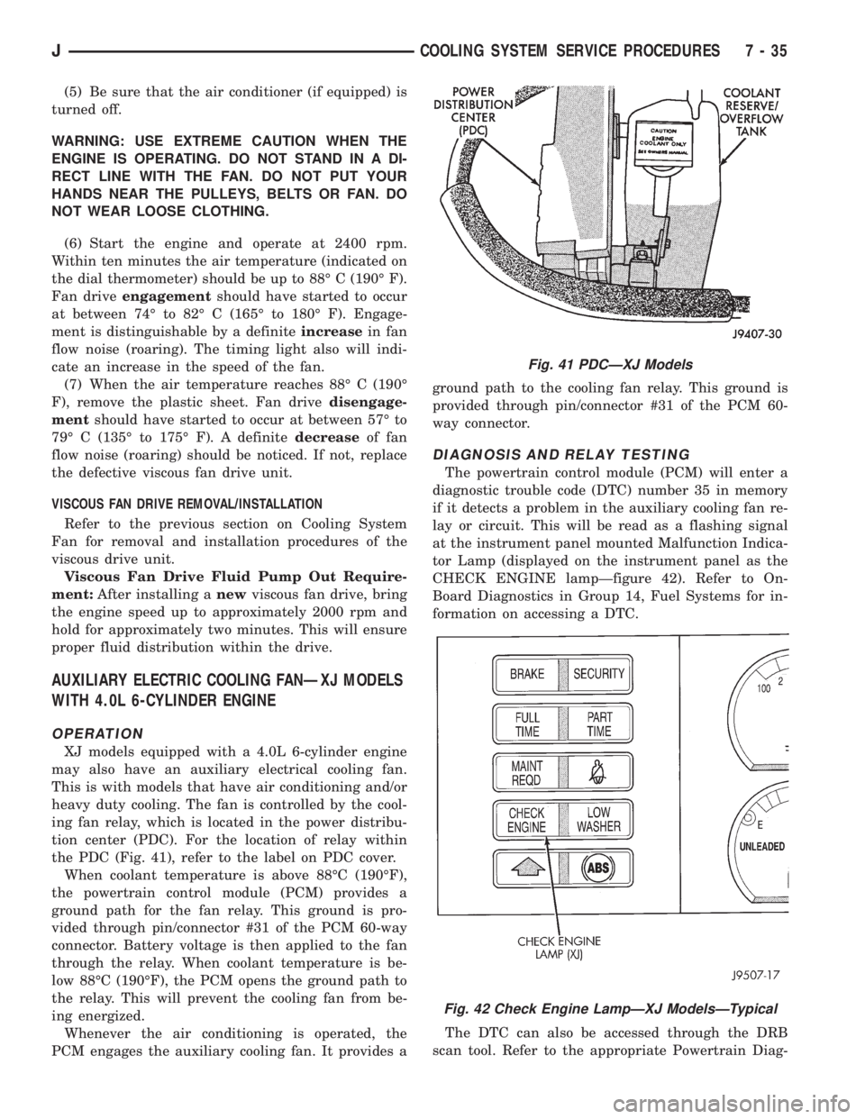
ing fan relay, which is located in the power distribu-
tion center (PDC). For the location of relay within
the PDC (Fig. 41), refer to the label on PDC cover.
When coolant temperature is above 88ÉC (190ÉF),
the powertrain control module (PCM) provides a
ground path for the fan relay. This ground is pro-
vided through pin/connector #31 of the PCM 60-way
connector. Battery voltage is then applied to the fan
through the relay. When coolant temperature is be-
low 88ÉC (190ÉF), the PCM opens the ground path to
the relay. This will prevent the cooling fan from be-
ing energized.
Whenever the air conditioning is operated, the
PCM engages the auxiliary cooling fan. It provides aground path to the cooling fan relay. This ground is
provided through pin/connector #31 of the PCM 60-
way connector.
DIAGNOSIS AND RELAY TESTING
The powertrain control module (PCM) will enter a
diagnostic trouble code (DTC) number 35 in memory
if it detects a problem in the auxiliary cooling fan re-
lay or circuit. This will be read as a flashing signal
at the instrument panel mounted Malfunction Indica-
tor Lamp (displayed on the instrument panel as the
CHECK ENGINE lampÐfigure 42). Refer to On-
Board Diagnostics in Group 14, Fuel Systems for in-
formation on accessing a DTC.
The DTC can also be accessed through the DRB
scan tool. Refer to the appropriate Powertrain Diag-
Fig. 41 PDCÐXJ Models
Fig. 42 Check Engine LampÐXJ ModelsÐTypical
JCOOLING SYSTEM SERVICE PROCEDURES 7 - 35
Page 281 of 2198
IGNITION-OFF DRAW
GENERAL INFORMATION
Ignition-Off Draw (IOD) refers to power being
drained from the battery with the ignition switch
turned OFF. A normal vehicle electrical system will
draw from 5 to 20 milliamps (0.005 - 0.020 amps).
This is with the ignition switch in the OFF position,
and all non-ignition controlled circuits in proper
working order. The 20 milliamps are needed to sup-
ply PCM memory, digital clock memory, and electron-
ically-tuned radio memory.
A vehicle that has not been operated for approxi-
mately 20 days, may discharge the battery to an in-
adequate level. When a vehicle will not be used for
20 days or more (stored), remove the IOD fuse in the
Power Distribution Center (PDC). This will reduce
battery discharging.
Excessive battery drain can be caused by:
²electrical items left on
²faulty or improperly adjusted switches
²internally shorted generator
²intermittent shorts in the wiring.
If the IOD is over 20 milliamps, the problem must
be found and corrected before replacing a battery. In
most cases, the battery can be charged and returned
to service.
DIAGNOSIS
Testing for high-amperage IOD must be per-
formed first to prevent damage to most milli-
amp meters.
(1) Verify that all electrical accessories are off.
Turn off all lamps, remove ignition key, and close all
doors. If the vehicle is equipped with illuminated en-
try or electronically-tuned radio, allow the systems to
automatically shut off (time out). This may take up
to 3 minutes.
(2) Determine that the underhood lamp is operat-
ing properly, then disconnect or remove bulb.
(3) Disconnect negative cable from battery.
(4) Connect a typical 12-volt test lamp (low-watt-
age bulb) between the negative cable clamp and the
battery negative terminal. Make sure that the doors
remain closed so that illuminated entry is not acti-
vated.The test lamp may light brightly for up to 3 min-
utes, or may not light at all, depending upon the ve-
hicle's electrical equipment. The term brightly, as
used throughout the following tests, implies the
brightness of the test lamp will be the same as if it
were connected across the battery.
The test lamp must be securely clamped to the neg-
ative cable clamp and battery negative terminal. If
the test lamp becomes disconnected during any part
of the IOD test, the electronic timer function will be
activated and all tests must be repeated.
(5) After 3 minutes the test lamp should turn off
or be dimly lit, depending upon the vehicle's electri-
cal equipment. If the test lamp remains brightly lit,
do not disconnect it. Remove each fuse or circuit
breaker (refer to Group 8W - Wiring Diagrams) until
test lamp is either off or dimly lit. This will isolate
each circuit and identify the source of the high-am-
perage draw.
If the test lamp is still brightly lit after disconnect-
ing each fuse and circuit breaker, disconnect the wir-
ing harness from the generator. If test lamp now
turns off or is dimly lit, see Charging System in this
group to diagnose faulty generator. Do not disconnect
the test lamp.
After high-amperage IOD has been corrected, low-
amperage IOD may be checked. It is now safe to in-
stall a milliamp meter to check for low- amperage
IOD.
(6) With test lamp still connected securely, clamp a
milliamp meter between battery negative terminal
and negative cable clamp.
Do not open any doors or turn on any electri-
cal accessories with the test lamp disconnected
or the milliamp meter may be damaged.
(7) Disconnect test lamp. Observe milliamp meter.
The current draw should not exceed 0.020 amp. If
draw exceeds 20 milliamps, isolate each circuit by re-
moving circuit breakers and fuses. The milliamp
meter reading will drop when the source of the draw
is disconnected. Repair this circuit as necessary,
whether a wiring short, incorrect switch adjustment
or a component failure is found.
8A - 10 BATTERY/STARTING/CHARGING SYSTEMS DIAGNOSTICSJ
Page 284 of 2198
COLD CRANKING TEST
(1) Battery must be fully-charged and load tested
before proceeding. See Battery, in this group.
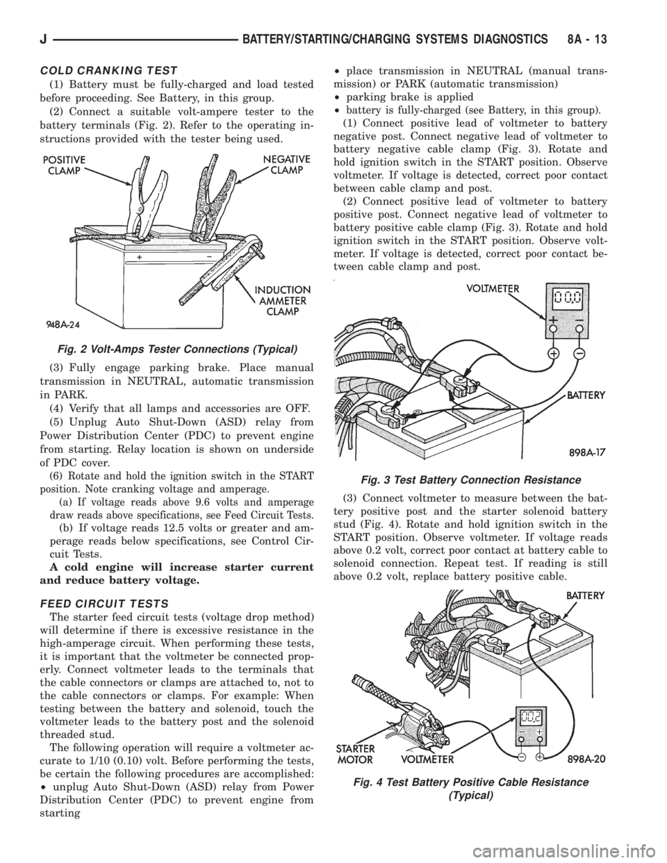
(2) Connect a suitable volt-ampere tester to the
battery terminals (Fig. 2). Refer to the operating in-
structions provided with the tester being used.
(3) Fully engage parking brake. Place manual
transmission in NEUTRAL, automatic transmission
in PARK.
(4) Verify that all lamps and accessories are OFF.
(5) Unplug Auto Shut-Down (ASD) relay from
Power Distribution Center (PDC) to prevent engine
from starting. Relay location is shown on underside
of PDC cover.
(6) Rotate and hold the ignition switch in the START
position. Note cranking voltage and amperage.
(a) If voltage reads above 9.6 volts and amperage
draw reads above specifications, see Feed Circuit Tests.
(b) If voltage reads 12.5 volts or greater and am-
perage reads below specifications, see Control Cir-
cuit Tests.
A cold engine will increase starter current
and reduce battery voltage.
FEED CIRCUIT TESTS
The starter feed circuit tests (voltage drop method)
will determine if there is excessive resistance in the
high-amperage circuit. When performing these tests,
it is important that the voltmeter be connected prop-
erly. Connect voltmeter leads to the terminals that
the cable connectors or clamps are attached to, not to
the cable connectors or clamps. For example: When
testing between the battery and solenoid, touch the
voltmeter leads to the battery post and the solenoid
threaded stud.
The following operation will require a voltmeter ac-
curate to 1/10 (0.10) volt. Before performing the tests,
be certain the following procedures are accomplished:
²unplug Auto Shut-Down (ASD) relay from Power
Distribution Center (PDC) to prevent engine from
starting²place transmission in NEUTRAL (manual trans-
mission) or PARK (automatic transmission)
²parking brake is applied
²
battery is fully-charged (see Battery, in this group).
(1) Connect positive lead of voltmeter to battery
negative post. Connect negative lead of voltmeter to
battery negative cable clamp (Fig. 3). Rotate and
hold ignition switch in the START position. Observe
voltmeter. If voltage is detected, correct poor contact
between cable clamp and post.
(2) Connect positive lead of voltmeter to battery
positive post. Connect negative lead of voltmeter to
battery positive cable clamp (Fig. 3). Rotate and hold
ignition switch in the START position. Observe volt-
meter. If voltage is detected, correct poor contact be-
tween cable clamp and post.
(3) Connect voltmeter to measure between the bat-
tery positive post and the starter solenoid battery
stud (Fig. 4). Rotate and hold ignition switch in the
START position. Observe voltmeter. If voltage reads
above 0.2 volt, correct poor contact at battery cable to
solenoid connection. Repeat test. If reading is still
above 0.2 volt, replace battery positive cable.
Fig. 2 Volt-Amps Tester Connections (Typical)
Fig. 3 Test Battery Connection Resistance
Fig. 4 Test Battery Positive Cable Resistance
(Typical)
JBATTERY/STARTING/CHARGING SYSTEMS DIAGNOSTICS 8A - 13
Page 285 of 2198

(4) Connect voltmeter to measure between the bat-
tery negative post and a good clean ground on the
engine block (Fig. 5). Rotate and hold ignition switch
in the START position. Observe voltmeter. If voltage
reads above 0.2 volt, correct poor contact at battery
negative cable attaching point. Repeat test. If read-
ing is still above 0.2 volt, replace battery negative ca-
ble.
(5) Connect positive lead of voltmeter to starter
housing. Connect negative lead of voltmeter to bat-
tery negative terminal (Fig. 6). Rotate and hold igni-
tion switch in the START position. Observe
voltmeter. If voltage reads above 0.2 volt, correct poor
starter to engine ground.
If resistance tests detect no feed circuit problems,
remove the starter and see Solenoid Test in this
group.
CONTROL CIRCUIT TESTS
The starter control circuit consists of:
²starter solenoid
²starter relay
²ignition switch
²park/neutral position switch (automatic transmis-
sion)²wiring harness and connections.
Test procedures for these components are as fol-
lows, and should be followed in the order described.
CAUTION: Before performing any test, unplug Auto
Shut-Down (ASD) relay from Power Distribution
Center (PDC) to prevent engine from starting.
SOLENOID TEST
Refer to Group 8B - Battery/Starter/Generator Ser-
vice for starter removal procedures.
(1) Disconnect solenoid field coil wire from field
coil terminal.
(2) Check for continuity between solenoid terminal
and field coil terminal with a continuity tester. There
should be continuity (Fig. 7).
(3) Check for continuity between solenoid terminal
and solenoid case. There should be continuity (Fig.
8).
(4) If there is continuity, solenoid is good. If there
is no continuity in either test, solenoid has an open
circuit and is faulty. Replace starter assembly.
(5) Connect solenoid field coil wire to field coil ter-
minal.
(6) Install starter as described in Group 8B - Bat-
tery/Starter/Generator Service.
RELAY TEST
The starter relay is in the Power Distribution Cen-
ter (PDC)(Figs. 9 or 10). Refer to the underside of the
PDC cover for relay location.
Fig. 5 Test Ground Circuit Resistance
Fig. 6 Test Starter Ground (Typical)
Fig. 7 Continuity Test Between Solenoid Terminal
and Field Coil Terminal
Fig. 8 Continuity Test Between Solenoid Terminal
and Solenoid Case
8A - 14 BATTERY/STARTING/CHARGING SYSTEMS DIAGNOSTICSJ
Page 286 of 2198
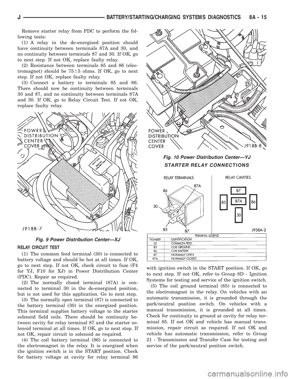
Remove starter relay from PDC to perform the fol-
lowing tests:
(1) A relay in the de-energized position should
have continuity between terminals 87A and 30, and
no continuity between terminals 87 and 30. If OK, go
to next step. If not OK, replace faulty relay.
(2) Resistance between terminals 85 and 86 (elec-
tromagnet) should be 7565 ohms. If OK, go to next
step. If not OK, replace faulty relay.
(3) Connect a battery to terminals 85 and 86.
There should now be continuity between terminals
30 and 87, and no continuity between terminals 87A
and 30. If OK, go to Relay Circuit Test. If not OK,
replace faulty relay.
RELAY CIRCUIT TEST
(1) The common feed terminal (30) is connected to
battery voltage and should be hot at all times. If OK,
go to next step. If not OK, check circuit to fuse (F4
for YJ, F10 for XJ) in Power Distribution Center
(PDC). Repair as required.
(2) The normally closed terminal (87A) is con-
nected to terminal 30 in the de-energized position,
but is not used for this application. Go to next step.
(3) The normally open terminal (87) is connected to
the battery terminal (30) in the energized position.
This terminal supplies battery voltage to the starter
solenoid field coils. There should be continuity be-
tween cavity for relay terminal 87 and the starter so-
lenoid terminal at all times. If OK, go to next step. If
not OK, repair circuit to solenoid as required.
(4) The coil battery terminal (86) is connected to
the electromagnet in the relay. It is energized when
the ignition switch is in the START position. Check
for battery voltage at cavity for relay terminal 86with ignition switch in the START position. If OK, go
to next step. If not OK, refer to Group 8D - Ignition
Systems for testing and service of the ignition switch.
(5) The coil ground terminal (85) is connected to
the electromagnet in the relay. On vehicles with an
automatic transmission, it is grounded through the
park/neutral position switch. On vehicles with a
manual transmission, it is grounded at all times.
Check for continuity to ground at cavity for relay ter-
minal 85. If not OK and vehicle has manual trans-
mission, repair circuit as required. If not OK and
vehicle has automatic transmission, refer to Group
21 - Transmission and Transfer Case for testing and
service of the park/neutral position switch.
Fig. 9 Power Distribution CenterÐXJ
Fig. 10 Power Distribution CenterÐYJ
STARTER RELAY CONNECTIONS
JBATTERY/STARTING/CHARGING SYSTEMS DIAGNOSTICS 8A - 15
Page 289 of 2198
²accessories being left on with the engine not run-
ning
²a faulty or improperly adjusted switch that allows
a lamp to stay on (see Ignition-Off Draw, in this
group).
INSPECTION
(1) Inspect condition of battery cable terminals,
battery posts, connections at engine block, starter so-
lenoid and relay. They should be clean and tight. Re-
pair as required.
(2) Inspect all fuses in the fuseblock module and
Power Distribution Center (PDC) for tightness in re-
ceptacles. They should be properly installed and
tight. Repair or replace as required.
(3) Inspect the electrolyte level in the battery. If
cell caps are removable, add water if required. If cell
caps are not removable, replace battery if electrolyte
level is low.
(4) Inspect generator mounting bolts for tightness.
Replace or tighten bolts, if required. Refer to Group
8B - Battery/Starter/Generator Service for torque
specifications.
(5) Inspect generator drive belt condition and ten-
sion. Tighten or replace belt as required. Refer to
Belt Tension Specifications in Group 7 - Cooling Sys-
tem.
(6) Inspect connections at generator field, battery
output, and ground terminals. Also check ground con-
nection at engine. They should all be clean and tight.
Repair as required.
OUTPUT WIRE RESISTANCE TEST
This test will show the amount of voltage drop
across the generator output wire, from the generator
battery terminal to the battery positive post.
PREPARATION
(1) Before starting test make sure vehicle has a
fully-charged battery. See Battery in this group for
more information.
(2) Turn ignition switch to OFF.
(3) Disconnect negative cable from battery.
(4) Disconnect generator output wire from genera-
tor battery output terminal.
(5) Connect a 0-150 ampere scale DC ammeter
(Fig. 2). Install in series between generator battery
output terminal and disconnected generator output
wire. Connect positive lead to generator battery out-
put terminal and negative lead to disconnected gen-
erator output wire.
(6) Connect positive lead of a test voltmeter (range
0-18 volts minimum) to disconnected generator out-
put wire. Connect negative lead of test voltmeter to
battery positive cable at positive post.
(7) Connect one end of a jumper wire to ground
and with other end probe green K20 field wire at
back of generator (Fig. 2). This will generate a DTC.CAUTION: Do not connect green/orange A142 field
wire to ground. Refer to Group 8W - Wiring Dia-
grams for more information.
(8) Connect an engine tachometer, then connect
battery negative cable to battery.
(9) Connect a variable carbon pile rheostat be-
tween battery terminals. Be sure carbon pile is in
OPEN or OFF position before connecting leads. See
Load Test in this group for instructions.
TEST
(1) Start engine. Immediately after starting, re-
duce engine speed to idle.
(2) Adjust engine speed and carbon pile to main-
tain 20 amperes flowing in circuit. Observe voltmeter
reading. Voltmeter reading should not exceed 0.5
volts.
RESULTS
If a higher voltage drop is indicated, inspect, clean
and tighten all connections. This includes any con-
nection between generator battery output terminal
and battery positive post. A voltage drop test may be
performed at each connection to locate the connection
with excessive resistance. If resistance tests satisfac-
torily, reduce engine speed, turn OFF carbon pile and
turn OFF ignition switch.
(1) Disconnect negative cable from battery.
(2) Remove test ammeter, voltmeter, carbon pile,
and tachometer.
(3) Remove jumper wire.
(4) Connect generator output wire to generator
battery output terminal. Tighten nut to 8.561.5 Nzm
(75615 in. lbs.).
(5) Connect negative cable to battery.
(6) Use DRB scan tool to erase DTC.
CURRENT OUTPUT TEST
The generator current output test determines
whether generator can deliver its rated current out-
put.
PREPARATION
(1) Before starting test make sure vehicle has a
fully-charged battery. See Battery in this group for
more information.
(2) Disconnect negative cable from battery.
(3) Disconnect generator output wire at the gener-
ator battery output terminal.
(4) Connect a 0-150 ampere scale DC ammeter
(Fig. 3). Install in series between generator battery
output terminal and disconnected generator output
wire. Connect positive lead to generator battery out-
put terminal and negative lead to disconnected gen-
erator output wire.
8A - 18 BATTERY/STARTING/CHARGING SYSTEMS DIAGNOSTICSJ
Page 299 of 2198
CAUTION: Be certain that battery cables are con-
nected to the correct battery terminals. Reverse po-
larity can damage electrical components.
(12) Place oiled felt washer on battery positive ter-
minal post.
(13) Install and tighten battery positive cable ter-
minal clamp. Then install and tighten negative cableterminal clamp. Both cable clamp bolts require
torque of 8.5 Nzm (75 in. lbs.).
(14) Apply a thin coating of petroleum jelly or
chassis grease to cable terminals and battery posts.
STARTER AND STARTER RELAY
GENERAL INFORMATION
This section covers starter and starter relay service
procedures only. For diagnostic procedures, refer to
Group 8A - Battery/Starting/Charging Systems Diag-
nostics. Service procedures for other starting system
components can be found as follows:
²battery - see Battery, in this group
²ignition switch - refer to Group 8D - Ignition Sys-
tems
²park/neutral position switch (automatic transmis-
sion) - refer to Group 21 - Transmission and Transfer
Case
²wiring harness and connectors - refer to Group 8W
- Wiring Diagrams.
STARTER
The starter motor incorporates several features to
create a reliable, efficient, compact and lightweight
unit. A planetary gear system (intermediate trans-
mission) is used between the electric motor and pin-
ion gear. This feature makes it possible to reduce the
dimensions of the starter. At the same time, it allows
higher armature rotational speed and delivers in-
creased torque through the pinion gear to the fly-
wheel or drive plate ring gear.
The use of a permanent magnet field also reduces
starter size and weight. This field consists of six
high-strength permanent magnets. The magnets are
aligned according to their polarity and are perma-
nently fixed in the starter field frame.
The starter motors for all engines are activated by
a solenoid mounted to the overrunning clutch hous-
ing. However, the starter motor/solenoid are serviced
only as a complete assembly. If either component
fails, the entire assembly must be replaced.
This unit is highly sensitive to hammering, shocks
and external pressure.
CAUTION: The starter motor MUST NOT BE
CLAMPED in a vise by the starter field frame. Doing
so may damage the magnets. It may be clamped by
the mounting flange ONLY.CAUTION: Do not connect starter motor incorrectly
when tests are being performed. The permanent
magnets may be damaged and rendered unservice-
able.
STARTER RELAY
The starter relay is an International Standards Or-
ganization (ISO) type relay, and is located in the
Power Distribution Center (PDC). Refer to underside
of PDC cover for relay location.
STARTER REMOVE/INSTALLÐ2.5L
XJ MODELS
(1) Disconnect battery negative cable.
(2) Remove exhaust clamp from bracket (Fig. 11).
(3) Remove nut and bolt from forward end of brace
rod (automatic transmission only).
Fig. 11 Exhaust Clamp and Brace Remove (XJÐ
2.5L)
8B - 4 BATTERY/STARTER/GENERATOR SERVICEJ
Page 301 of 2198
STARTER RELAY REMOVE/INSTALL
(1) Disconnect battery negative cable.
(2) Remove starter relay by unplugging unit from
PDC (Fig. 15 or 16).(3) Install starter relay by aligning relay terminals
with cavities in PDC and plugging relay in.
(4) Connect negative cable to battery.
(5) Test relay operation.
GENERATOR
GENERAL INFORMATION
This section covers generator service procedures
only. For generator or charging system diagnosis, re-
fer to Group 8A - Battery/Starting/Charging Systems
Diagnostics.
The generator is belt-driven by the engine. All en-
gines use serpentine drive. The generator is serviced
only as a complete assembly. If the generator fails for
any reason, the entire assembly must be replaced.
Two generator output ratings are available, de-
pending upon optional equipment. Be certain that
the replacement generator has the same output rat-
ing as the original unit. Refer to Group 8A - Battery/
Starting/Charging Systems Diagnostics and see
Specifications.
The generator field control (voltage regulator) cir-
cuitry is internal to the Powertrain Control Module
(PCM). If faulty, the entire PCM must be replaced.
Refer to Group 14 - Fuel System for PCM service
procedure.
GENERATOR REMOVE/INSTALLÐLEFT-HAND
DRIVE
WARNING: DISCONNECT NEGATIVE CABLE FROM
BATTERY BEFORE REMOVING BATTERY OUTPUT
WIRE FROM GENERATOR. FAILURE TO DO SO
CAN RESULT IN INJURY.
ALL WITH 2.5L AND YJ WITH 4.0L
(1) Disconnect battery negative cable.
(2) Remove generator drive belt. Refer to Group 7 -
Cooling System for procedure.
(3) Remove generator battery output terminal nut,
2 field terminal nuts, ground and harness holddown
nuts (Fig. 17). Remove wire connector assembly.
(4) Remove 2 generator mounting bolts and remove
generator from vehicle.
(5) Reverse removal procedure to install. Torque
generator hardware as shown in Specifications.
CAUTION: Never force a belt over a pulley rim us-
ing a screwdriver. The synthetic fiber of the belt can
be damaged.
Fig. 15 Power Distribution CenterÐXJFig. 16 Power Distribution CenterÐYJ
8B - 6 BATTERY/STARTER/GENERATOR SERVICEJ