1995 JEEP CHEROKEE fuel
[x] Cancel search: fuelPage 828 of 2198
POWER DISTRIBUTION
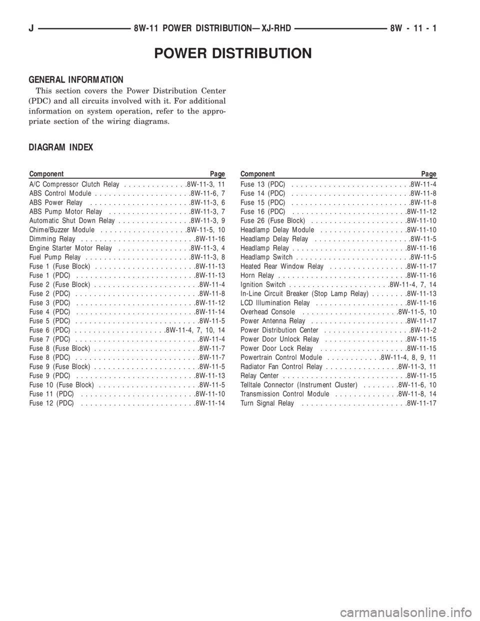
GENERAL INFORMATION
This section covers the Power Distribution Center
(PDC) and all circuits involved with it. For additional
information on system operation, refer to the appro-
priate section of the wiring diagrams.
DIAGRAM INDEX
Component Page
A/C Compressor Clutch Relay..............8W-11-3, 11
ABS Control Module.....................8W-11-6, 7
ABS Power Relay......................8W-11-3, 6
ABS Pump Motor Relay..................8W-11-3, 7
Automatic Shut Down Relay................8W-11-3, 9
Chime/Buzzer Module...................8W-11-5, 10
Dimming Relay.........................8W-11-16
Engine Starter Motor Relay................8W-11-3, 4
Fuel Pump Relay.......................8W-11-3, 8
Fuse 1 (Fuse Block)......................8W-11-13
Fuse 1 (PDC)..........................8W-11-13
Fuse 2 (Fuse Block).......................8W-11-4
Fuse 2 (PDC)...........................8W-11-8
Fuse 3 (PDC)..........................8W-11-12
Fuse 4 (PDC)..........................8W-11-14
Fuse 5 (PDC)...........................8W-11-5
Fuse 6 (PDC)....................8W-11-4, 7, 10, 14
Fuse 7 (PDC)...........................8W-11-4
Fuse 8 (Fuse Block).......................8W-11-7
Fuse 8 (PDC)...........................8W-11-7
Fuse 9 (Fuse Block).......................8W-11-5
Fuse 9 (PDC)..........................8W-11-13
Fuse 10 (Fuse Block)......................8W-11-5
Fuse 11 (PDC).........................8W-11-10
Fuse 12 (PDC).........................8W-11-14Component Page
Fuse 13 (PDC)..........................8W-11-4
Fuse 14 (PDC)..........................8W-11-8
Fuse 15 (PDC)..........................8W-11-8
Fuse 16 (PDC).........................8W-11-12
Fuse 26 (Fuse Block).....................8W-11-10
Headlamp Delay Module...................8W-11-10
Headlamp Delay Relay.....................8W-11-5
Headlamp Relay.........................8W-11-16
Headlamp Switch.........................8W-11-5
Heated Rear Window Relay.................8W-11-17
Horn Relay............................8W-11-16
Ignition Switch......................8W-11-4, 7, 14
In-Line Circuit Breaker (Stop Lamp Relay)........8W-11-13
LCD Illumination Relay....................8W-11-16
Overhead Console.....................8W-11-5, 10
Power Antenna Relay.....................8W-11-17
Power Distribution Center...................8W-11-2
Power Door Unlock Relay..................8W-11-15
Power Door Lock Relay...................8W-11-15
Powertrain Control Module............8W-11-4, 8, 9, 11
Radiator Fan Control Relay................8W-11-3, 11
Relay Center...........................8W-11-15
Telltale Connector (Instrument Cluster)........8W-11-6, 10
Transmission Control Module..............8W-11-8, 14
Turn Signal Relay.......................8W-11-17
J8W-11 POWER DISTRIBUTIONÐXJ-RHD 8W - 11 - 1
Page 852 of 2198
CHARGING SYSTEM
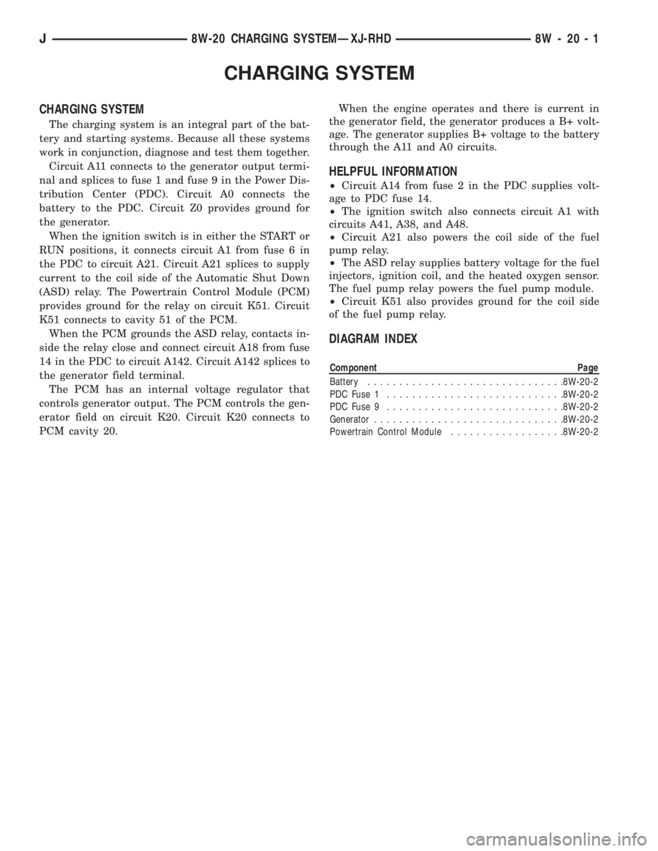
CHARGING SYSTEM
The charging system is an integral part of the bat-
tery and starting systems. Because all these systems
work in conjunction, diagnose and test them together.
Circuit A11 connects to the generator output termi-
nal and splices to fuse 1 and fuse 9 in the Power Dis-
tribution Center (PDC). Circuit A0 connects the
battery to the PDC. Circuit Z0 provides ground for
the generator.
When the ignition switch is in either the START or
RUN positions, it connects circuit A1 from fuse 6 in
the PDC to circuit A21. Circuit A21 splices to supply
current to the coil side of the Automatic Shut Down
(ASD) relay. The Powertrain Control Module (PCM)
provides ground for the relay on circuit K51. Circuit
K51 connects to cavity 51 of the PCM.
When the PCM grounds the ASD relay, contacts in-
side the relay close and connect circuit A18 from fuse
14 in the PDC to circuit A142. Circuit A142 splices to
the generator field terminal.
The PCM has an internal voltage regulator that
controls generator output. The PCM controls the gen-
erator field on circuit K20. Circuit K20 connects to
PCM cavity 20.When the engine operates and there is current in
the generator field, the generator produces a B+ volt-
age. The generator supplies B+ voltage to the battery
through the A11 and A0 circuits.
HELPFUL INFORMATION
²Circuit A14 from fuse 2 in the PDC supplies volt-
age to PDC fuse 14.
²The ignition switch also connects circuit A1 with
circuits A41, A38, and A48.
²Circuit A21 also powers the coil side of the fuel
pump relay.
²The ASD relay supplies battery voltage for the fuel
injectors, ignition coil, and the heated oxygen sensor.
The fuel pump relay powers the fuel pump module.
²Circuit K51 also provides ground for the coil side
of the fuel pump relay.
DIAGRAM INDEX
Component Page
Battery...............................8W-20-2
PDC Fuse 1............................8W-20-2
PDC Fuse 9............................8W-20-2
Generator..............................8W-20-2
Powertrain Control Module..................8W-20-2
J8W-20 CHARGING SYSTEMÐXJ-RHD 8W - 20 - 1
Page 856 of 2198
FUEL/IGNITION
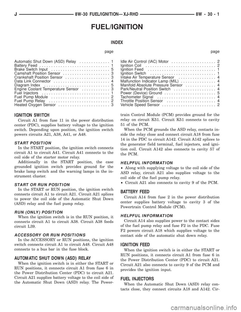
INDEX
page page
Automatic Shut Down (ASD) Relay............. 1
Battery Feed.............................. 1
Brake Switch Input......................... 5
Camshaft Position Sensor.................... 3
Crankshaft Position Sensor................... 3
Data Link Connector........................ 4
Diagram Index............................ 5
Engine Coolant Temperature Sensor............ 3
Fuel Injectors............................. 1
Fuel Pump Module......................... 2
Fuel Pump Relay.......................... 2
Heated Oxygen Sensor...................... 3Idle Air Control (IAC) Motor................... 2
Ignition Coil.............................. 2
Ignition Feed............................. 1
Ignition Switch............................ 1
Intake Air Temperature Sensor................ 4
Malfunction Indicator Lamp (MIL)............... 4
Manifold Absolute Pressure Sensor............. 4
Park/Neutral Position Switch.................. 4
Power (Device) Ground...................... 5
Tachometer Signal......................... 4
Throttle Position Sensor..................... 4
Vehicle Speed Sensor....................... 2
IGNITION SWITCH
Circuit A1 from fuse 11 in the power distribution
center (PDC), supplies battery voltage to the ignition
switch. Depending upon position, the ignition switch
powers circuits A21, A38, A41, or A48.
START POSITION
In the START position, the ignition switch connects
circuit A1 to circuit A41. Circuit A41 connects to the
coil side of the starter motor relay.
Additionally in the START position, the case
grounded ignition switch provides ground for the
brake lamp switch and the warning lamps in the in-
strument cluster.
START OR RUN POSITION
In the START or RUN position, the ignition switch
connects circuit A1 to circuit A21. Circuit A21 splices
to power the coil side of the Automatic Shut Down
(ASD) relay and the fuel pump relay.
RUN (ONLY) POSITION
When the ignition switch is in the RUN position, it
connects circuit A1 to circuit A38. Circuit A38 feeds
circuit L39.
ACCESSORY OR RUN POSITIONS
In the ACCESSORY or RUN positions, the ignition
switch connects circuit A1 to circuit A48. Circuit A48
connects to a bus bar in the fuse block.
AUTOMATIC SHUT DOWN (ASD) RELAY
When the ignition switch is in either the START or
RUN positions, it connects circuit A1 from fuse 6 in
the Power Distribution Center (PDC) to circuit A21.
Circuit A21 supplies battery voltage to the coil side of
the Automatic Shut Down (ASD) relay. The Power-train Control Module (PCM) provides ground for the
relay on circuit K51. Circuit K51 connects to cavity
51 of the PCM.
When the PCM grounds the ASD relay, contacts in-
side the relay close and connect circuit A18 from fuse
14 in the PDC to circuit A142. Circuit A142 splices to
the generator field terminal, fuel injectors, and igni-
tion coil. Circuit A142 also connects to cavity 57 of
the PCM.
HELPFUL INFORMATION
²Along with supplying voltage to the coil side of the
ASD relay, circuit A21 also supplies voltage to the
coil side of the fuel pump relay.
²Circuit A21 also connects to cavity 9 of the PCM.
BATTERY FEED
Circuit A14 from fuse 2 in the power distribution
center supplies battery voltage to cavity 3 of the
Powertrain Control Module (PCM).
HELPFUL INFORMATION
Circuit A14 also supplies power to the contact sides
of the fuel pump relay and fuse F2 in the PDC. Fuse
F2 powers circuit A18 which supplies voltage to the
contact side of the automatic shut down relay.
IGNITION FEED
When the ignition switch is in either the START or
RUN positions, it connects circuit A1 from fuse 6 in
the Power Distribution Center (PDC) to circuit A21.
Circuit A21 also connects to cavity 9 of the PCM and
provides the ignition input.
FUEL INJECTORS
When the Automatic Shut Down (ASD) relay con-
tacts close, they connect circuits A18 and A142. Cir-
J8W-30 FUEL/IGNITIONÐXJ-RHD 8W - 30 - 1
Page 857 of 2198
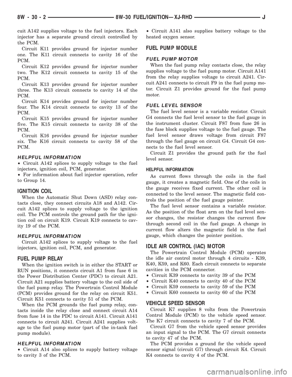
cuit A142 supplies voltage to the fuel injectors. Each
injector has a separate ground circuit controlled by
the PCM.
Circuit K11 provides ground for injector number
one. The K11 circuit connects to cavity 16 of the
PCM.
Circuit K12 provides ground for injector number
two. The K12 circuit connects to cavity 15 of the
PCM.
Circuit K13 provides ground for injector number
three. The K13 circuit connects to cavity 14 of the
PCM.
Circuit K14 provides ground for injector number
four. The K14 circuit connects to cavity 13 of the
PCM.
Circuit K15 provides ground for injector number
five. The K15 circuit connects to cavity 38 of the
PCM.
Circuit K16 provides ground for injector number
six. The K16 circuit connects to cavity 58 of the
PCM.
HELPFUL INFORMATION
²Circuit A142 splices to supply voltage to the fuel
injectors, ignition coil, PCM, generator.
²For information about fuel injector operation, refer
to Group 14.
IGNITION COIL
When the Automatic Shut Down (ASD) relay con-
tacts close, they connect circuits A18 and A142. Cir-
cuit A142 splices to supply voltage to the ignition
coil. The PCM controls the ground path for the igni-
tion coil on circuit K19. Circuit K19 connects to cav-
ity 19 of the PCM.
HELPFUL INFORMATION
Circuit A142 splices to supply voltage to the fuel
injectors, ignition coil, PCM, and generator.
FUEL PUMP RELAY
When the ignition switch is in either the START or
RUN positions, it connects circuit A1 from fuse 6 in
the Power Distribution Center (PDC) to circuit A21.
Circuit A21 supplies battery voltage to the coil side of
the fuel pump relay. The Powertrain Control Module
(PCM) provides ground for the relay on circuit K51.
Circuit K51 connects to cavity 51 of the PCM.
When the PCM grounds the fuel pump relay, con-
tacts inside the relay close and connect circuit A14
from fuse 14 in the PDC to circuit A141. Circuit A141
connects to circuit A241. Circuit A241 supplies volt-
age to the fuel pump motor (part of the in-tank fuel
pump module).
HELPFUL INFORMATION
²Circuit A14 also splices to supply battery voltage
to cavity 3 of the PCM.²Circuit A141 also supplies battery voltage to the
heated oxygen sensor.
FUEL PUMP MODULE
FUEL PUMP MOTOR
When the fuel pump relay contacts close, the relay
supplies voltage to the fuel pump motor. Circuit A141
from the relay supplies voltage to circuit A241. Cir-
cuit A241 connects to circuit F9 in the fuel pump mo-
tor. Circuit Z1 provides ground for the fuel pump
motor.
FUEL LEVEL SENSOR
The fuel level sensor is a variable resistor. Circuit
G4 connects the fuel level sensor to the fuel gauge in
the instrument cluster. Circuit F87 from fuse 26 in
the fuse block supplies voltage to the fuel gauge. The
fuel level sensor draws voltage from circuit F87
through the fuel gauge on circuit G4. Circuit G4 con-
nects to the fuel level sensor.
Circuit Z1 provides the ground path for the fuel
level sensor.
HELPFUL INFORMATION
As current flows through the coils in the fuel
gauge, it creates a magnetic field. One of the coils in
the gauge receives fixed current. The other coil is
connected to the level sensor. The magnetic field con-
trols the position of the fuel gauge pointer.
The fuel level sensor contains a variable resistor.
As the position of the float arm on the fuel level sen-
sor changes, the resistor changes the current flow
through second coil in the fuel gauge. A change in
current flow alters the magnetic field in the fuel
gauge, which changes the pointer position.
IDLE AIR CONTROL (IAC) MOTOR
The Powertrain Control Module (PCM) operates
the idle air control motor through 4 circuits - K39,
K40, K59, and K60. Each circuit connects to separate
cavities in the PCM connector.
²Circuit K39 connects to cavity 39 of the PCM
²Circuit K40 connects to cavity 40 of the PCM
²Circuit K59 connects to cavity 59 of the PCM
²Circuit K60 connects to cavity 60 of the PCM
VEHICLE SPEED SENSOR
Circuit K7 supplies 8 volts from the Powertrain
Control Module (PCM) to the vehicle speed sensor.
The K7 circuit connects to cavity 7 of the PCM.
Circuit G7 from the vehicle speed sensor provides
an input signal to the PCM. The G7 circuit connects
to cavity 47 of the PCM.
The PCM provides a ground for the vehicle speed
sensor signal (circuit G7) through circuit K4. Circuit
K4 connects to cavity 4 of the PCM.
8W - 30 - 2 8W-30 FUEL/IGNITIONÐXJ-RHDJ
Page 858 of 2198
HELPFUL INFORMATION
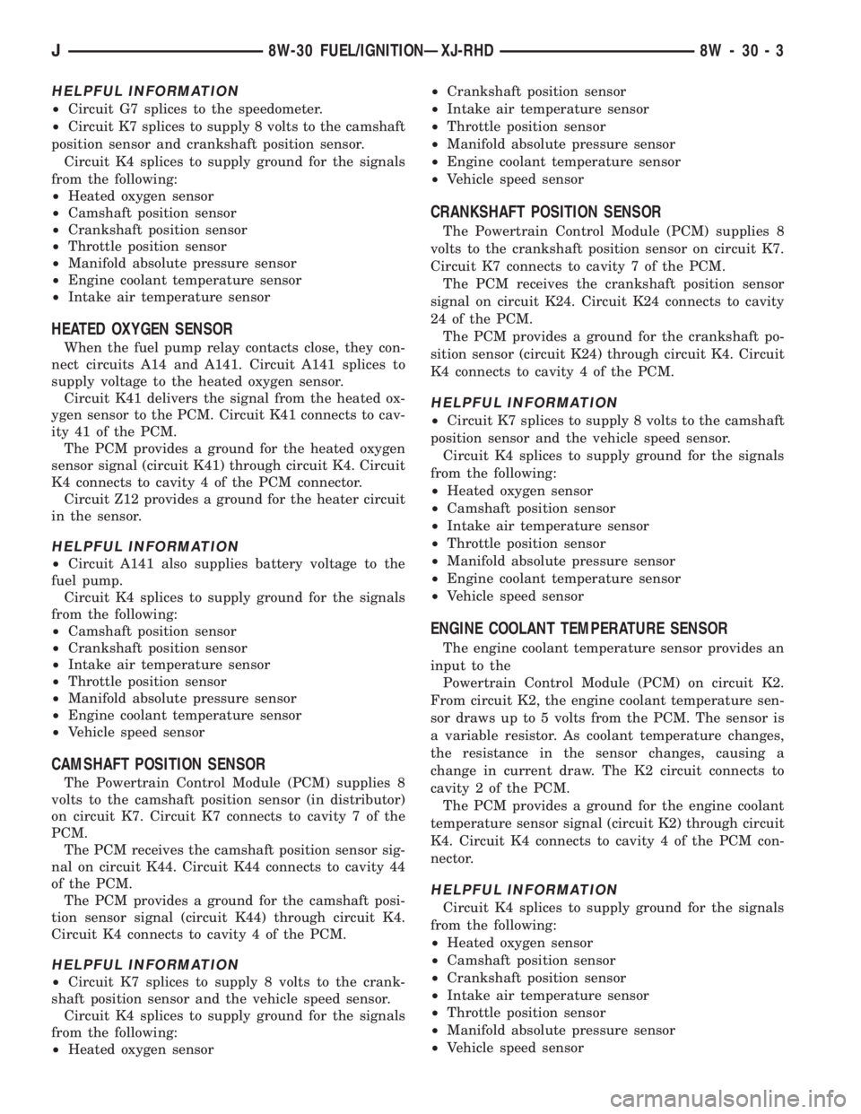
²Circuit G7 splices to the speedometer.
²Circuit K7 splices to supply 8 volts to the camshaft
position sensor and crankshaft position sensor.
Circuit K4 splices to supply ground for the signals
from the following:
²Heated oxygen sensor
²Camshaft position sensor
²Crankshaft position sensor
²Throttle position sensor
²Manifold absolute pressure sensor
²Engine coolant temperature sensor
²Intake air temperature sensor
HEATED OXYGEN SENSOR
When the fuel pump relay contacts close, they con-
nect circuits A14 and A141. Circuit A141 splices to
supply voltage to the heated oxygen sensor.
Circuit K41 delivers the signal from the heated ox-
ygen sensor to the PCM. Circuit K41 connects to cav-
ity 41 of the PCM.
The PCM provides a ground for the heated oxygen
sensor signal (circuit K41) through circuit K4. Circuit
K4 connects to cavity 4 of the PCM connector.
Circuit Z12 provides a ground for the heater circuit
in the sensor.
HELPFUL INFORMATION
²Circuit A141 also supplies battery voltage to the
fuel pump.
Circuit K4 splices to supply ground for the signals
from the following:
²Camshaft position sensor
²Crankshaft position sensor
²Intake air temperature sensor
²Throttle position sensor
²Manifold absolute pressure sensor
²Engine coolant temperature sensor
²Vehicle speed sensor
CAMSHAFT POSITION SENSOR
The Powertrain Control Module (PCM) supplies 8
volts to the camshaft position sensor (in distributor)
on circuit K7. Circuit K7 connects to cavity 7 of the
PCM.
The PCM receives the camshaft position sensor sig-
nal on circuit K44. Circuit K44 connects to cavity 44
of the PCM.
The PCM provides a ground for the camshaft posi-
tion sensor signal (circuit K44) through circuit K4.
Circuit K4 connects to cavity 4 of the PCM.
HELPFUL INFORMATION
²Circuit K7 splices to supply 8 volts to the crank-
shaft position sensor and the vehicle speed sensor.
Circuit K4 splices to supply ground for the signals
from the following:
²Heated oxygen sensor²Crankshaft position sensor
²Intake air temperature sensor
²Throttle position sensor
²Manifold absolute pressure sensor
²Engine coolant temperature sensor
²Vehicle speed sensor
CRANKSHAFT POSITION SENSOR
The Powertrain Control Module (PCM) supplies 8
volts to the crankshaft position sensor on circuit K7.
Circuit K7 connects to cavity 7 of the PCM.
The PCM receives the crankshaft position sensor
signal on circuit K24. Circuit K24 connects to cavity
24 of the PCM.
The PCM provides a ground for the crankshaft po-
sition sensor (circuit K24) through circuit K4. Circuit
K4 connects to cavity 4 of the PCM.
HELPFUL INFORMATION
²Circuit K7 splices to supply 8 volts to the camshaft
position sensor and the vehicle speed sensor.
Circuit K4 splices to supply ground for the signals
from the following:
²Heated oxygen sensor
²Camshaft position sensor
²Intake air temperature sensor
²Throttle position sensor
²Manifold absolute pressure sensor
²Engine coolant temperature sensor
²Vehicle speed sensor
ENGINE COOLANT TEMPERATURE SENSOR
The engine coolant temperature sensor provides an
input to the
Powertrain Control Module (PCM) on circuit K2.
From circuit K2, the engine coolant temperature sen-
sor draws up to 5 volts from the PCM. The sensor is
a variable resistor. As coolant temperature changes,
the resistance in the sensor changes, causing a
change in current draw. The K2 circuit connects to
cavity 2 of the PCM.
The PCM provides a ground for the engine coolant
temperature sensor signal (circuit K2) through circuit
K4. Circuit K4 connects to cavity 4 of the PCM con-
nector.
HELPFUL INFORMATION
Circuit K4 splices to supply ground for the signals
from the following:
²Heated oxygen sensor
²Camshaft position sensor
²Crankshaft position sensor
²Intake air temperature sensor
²Throttle position sensor
²Manifold absolute pressure sensor
²Vehicle speed sensor
J8W-30 FUEL/IGNITIONÐXJ-RHD 8W - 30 - 3
Page 859 of 2198
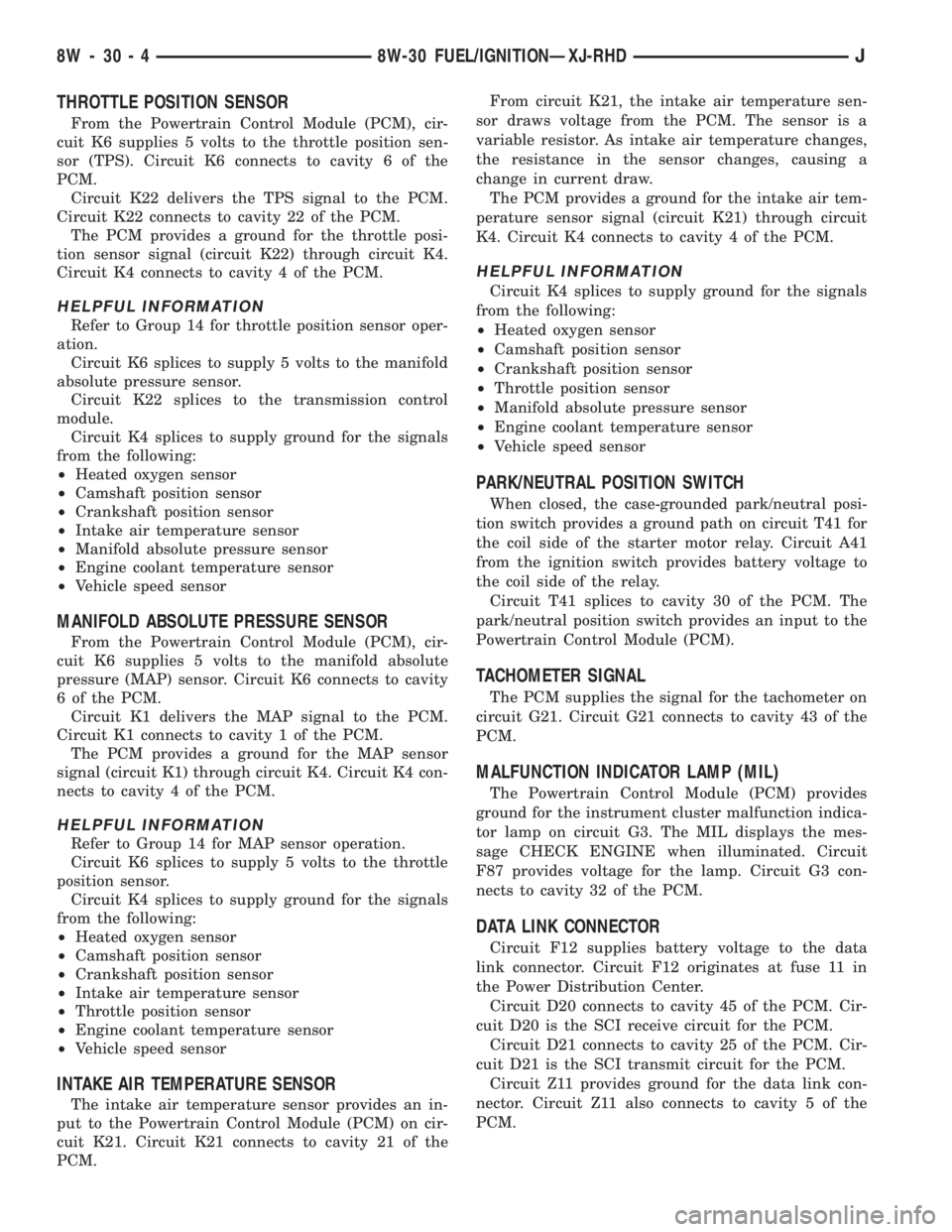
THROTTLE POSITION SENSOR
From the Powertrain Control Module (PCM), cir-
cuit K6 supplies 5 volts to the throttle position sen-
sor (TPS). Circuit K6 connects to cavity 6 of the
PCM.
Circuit K22 delivers the TPS signal to the PCM.
Circuit K22 connects to cavity 22 of the PCM.
The PCM provides a ground for the throttle posi-
tion sensor signal (circuit K22) through circuit K4.
Circuit K4 connects to cavity 4 of the PCM.
HELPFUL INFORMATION
Refer to Group 14 for throttle position sensor oper-
ation.
Circuit K6 splices to supply 5 volts to the manifold
absolute pressure sensor.
Circuit K22 splices to the transmission control
module.
Circuit K4 splices to supply ground for the signals
from the following:
²Heated oxygen sensor
²Camshaft position sensor
²Crankshaft position sensor
²Intake air temperature sensor
²Manifold absolute pressure sensor
²Engine coolant temperature sensor
²Vehicle speed sensor
MANIFOLD ABSOLUTE PRESSURE SENSOR
From the Powertrain Control Module (PCM), cir-
cuit K6 supplies 5 volts to the manifold absolute
pressure (MAP) sensor. Circuit K6 connects to cavity
6 of the PCM.
Circuit K1 delivers the MAP signal to the PCM.
Circuit K1 connects to cavity 1 of the PCM.
The PCM provides a ground for the MAP sensor
signal (circuit K1) through circuit K4. Circuit K4 con-
nects to cavity 4 of the PCM.
HELPFUL INFORMATION
Refer to Group 14 for MAP sensor operation.
Circuit K6 splices to supply 5 volts to the throttle
position sensor.
Circuit K4 splices to supply ground for the signals
from the following:
²Heated oxygen sensor
²Camshaft position sensor
²Crankshaft position sensor
²Intake air temperature sensor
²Throttle position sensor
²Engine coolant temperature sensor
²Vehicle speed sensor
INTAKE AIR TEMPERATURE SENSOR
The intake air temperature sensor provides an in-
put to the Powertrain Control Module (PCM) on cir-
cuit K21. Circuit K21 connects to cavity 21 of the
PCM.From circuit K21, the intake air temperature sen-
sor draws voltage from the PCM. The sensor is a
variable resistor. As intake air temperature changes,
the resistance in the sensor changes, causing a
change in current draw.
The PCM provides a ground for the intake air tem-
perature sensor signal (circuit K21) through circuit
K4. Circuit K4 connects to cavity 4 of the PCM.
HELPFUL INFORMATION
Circuit K4 splices to supply ground for the signals
from the following:
²Heated oxygen sensor
²Camshaft position sensor
²Crankshaft position sensor
²Throttle position sensor
²Manifold absolute pressure sensor
²Engine coolant temperature sensor
²Vehicle speed sensor
PARK/NEUTRAL POSITION SWITCH
When closed, the case-grounded park/neutral posi-
tion switch provides a ground path on circuit T41 for
the coil side of the starter motor relay. Circuit A41
from the ignition switch provides battery voltage to
the coil side of the relay.
Circuit T41 splices to cavity 30 of the PCM. The
park/neutral position switch provides an input to the
Powertrain Control Module (PCM).
TACHOMETER SIGNAL
The PCM supplies the signal for the tachometer on
circuit G21. Circuit G21 connects to cavity 43 of the
PCM.
MALFUNCTION INDICATOR LAMP (MIL)
The Powertrain Control Module (PCM) provides
ground for the instrument cluster malfunction indica-
tor lamp on circuit G3. The MIL displays the mes-
sage CHECK ENGINE when illuminated. Circuit
F87 provides voltage for the lamp. Circuit G3 con-
nects to cavity 32 of the PCM.
DATA LINK CONNECTOR
Circuit F12 supplies battery voltage to the data
link connector. Circuit F12 originates at fuse 11 in
the Power Distribution Center.
Circuit D20 connects to cavity 45 of the PCM. Cir-
cuit D20 is the SCI receive circuit for the PCM.
Circuit D21 connects to cavity 25 of the PCM. Cir-
cuit D21 is the SCI transmit circuit for the PCM.
Circuit Z11 provides ground for the data link con-
nector. Circuit Z11 also connects to cavity 5 of the
PCM.
8W - 30 - 4 8W-30 FUEL/IGNITIONÐXJ-RHDJ
Page 860 of 2198
HELPFUL INFORMATION
²If the system loses ground for the Z11 circuits at
the right rear of the engine, the vehicle will not op-
erate. Check the connection at the ganged-ground cir-
cuit eyelet.
²Circuit F12 splices to supply battery voltage to the
vehicle speed control switch, back-up lamp switch,
A/C compressor clutch relay, windshield washer fluid
level sensor and radiator fan relay.
BRAKE SWITCH INPUT
Circuit K29 provides the brake switch input to the
PCM. Circuit K29 connects to cavity 29 of the PCM.
POWER (DEVICE) GROUND
Circuit Z12 connects to cavities 11 and 12 of the
PCM. The Z12 circuit provides ground for PCM inter-
nal drivers that operate high current devices like the
injectors and ignition coil.
Internal to the PCM, the power (device) ground cir-
cuit connects to the PCM sensor return circuit (from
circuit K4).
HELPFUL INFORMATION
²The grounding point for circuit Z12 is the right
rear of the engine.
²If the system loses ground for the Z12 circuits at
the rear of the engine, the vehicle will not operate.
Check the connection at the ganged-ground circuit
eyelet.
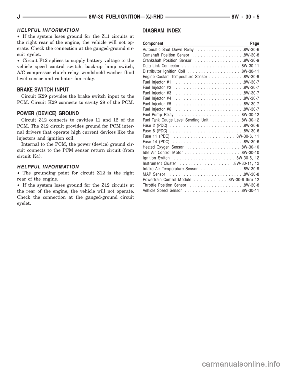
DIAGRAM INDEX
Component Page
Automatic Shut Down Relay.................8W-30-6
Camshaft Position Sensor...................8W-30-8
Crankshaft Position Sensor..................8W-30-9
Data Link Connector......................8W-30-11
Distributor Ignition Coil....................8W-30-11
Engine Coolant Temperature Sensor.............8W-30-9
Fuel Injector #1.........................8W-30-7
Fuel Injector #2.........................8W-30-7
Fuel Injector #3.........................8W-30-7
Fuel Injector #4.........................8W-30-7
Fuel Injector #5.........................8W-30-7
Fuel Injector #6.........................8W-30-7
Fuel Pump Relay........................8W-30-12
Fuel Tank Gauge Level Sending Unit...........8W-30-12
Fuse 2 (PDC)...........................8W-30-6
Fuse 6 (PDC)...........................8W-30-6
Fuse 11 (PDC).......................8W-30-6, 11
Fuse 14 (PDC)..........................8W-30-6
Heated Oxygen Sensor....................8W-30-10
Idle Air Control Motor.....................8W-30-10
Ignition Switch.......................8W-30-6, 12
Instrument Cluster....................8W-30-11, 12
Intake Air Temperature Sensor................8W-30-9
MAP Sensor............................8W-30-8
Powertrain Control Module.............8W-30-6 thru 12
Throttle Position Sensor....................8W-30-8
Vehicle Speed Sensor.....................8W-30-11
J8W-30 FUEL/IGNITIONÐXJ-RHD 8W - 30 - 5
Page 1065 of 2198
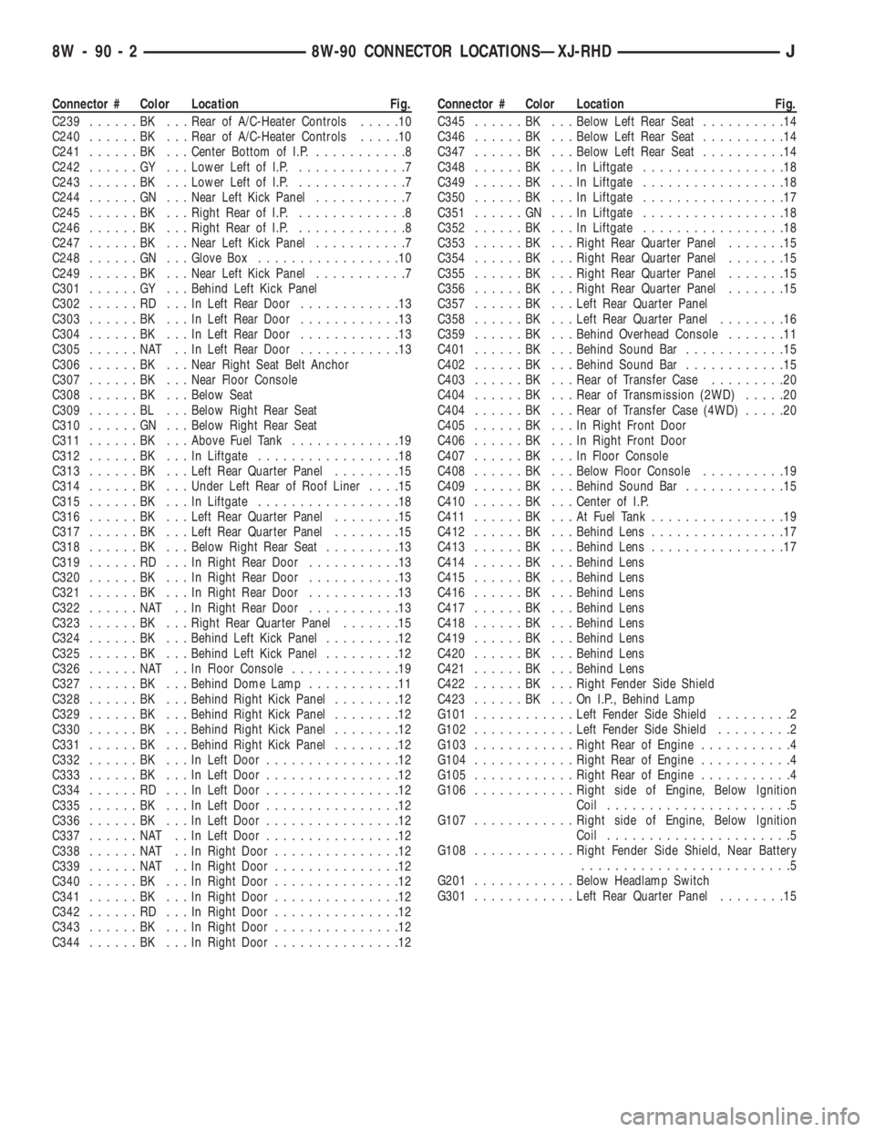
Connector # Color Location Fig.
C239......BK ...Rear of A/C-Heater Controls.....10
C240......BK ...Rear of A/C-Heater Controls.....10
C241......BK ...Center Bottom of I.P............8
C242......GY ...Lower Left of I.P..............7
C243......BK ...Lower Left of I.P..............7
C244......GN ...Near Left Kick Panel...........7
C245......BK ...Right Rear of I.P..............8
C246......BK ...Right Rear of I.P..............8
C247......BK ...Near Left Kick Panel...........7
C248......GN ...Glove Box.................10
C249......BK ...Near Left Kick Panel...........7
C301......GY ...Behind Left Kick Panel
C302......RD ...InLeft Rear Door............13
C303......BK ...InLeft Rear Door............13
C304......BK ...InLeft Rear Door............13
C305......NAT ..InLeft Rear Door............13
C306......BK ...Near Right Seat Belt Anchor
C307......BK ...Near Floor Console
C308......BK ...Below Seat
C309......BL ...Below Right Rear Seat
C310......GN ...Below Right Rear Seat
C311......BK ...Above Fuel Tank.............19
C312......BK ...InLiftgate.................18
C313......BK ...Left Rear Quarter Panel........15
C314......BK ...Under Left Rear of Roof Liner....15
C315......BK ...InLiftgate.................18
C316......BK ...Left Rear Quarter Panel........15
C317......BK ...Left Rear Quarter Panel........15
C318......BK ...Below Right Rear Seat.........13
C319......RD ...InRight Rear Door...........13
C320......BK ...InRight Rear Door...........13
C321......BK ...InRight Rear Door...........13
C322......NAT ..InRight Rear Door...........13
C323......BK ...Right Rear Quarter Panel.......15
C324......BK ...Behind Left Kick Panel.........12
C325......BK ...Behind Left Kick Panel.........12
C326......NAT ..InFloor Console.............19
C327......BK ...Behind Dome Lamp...........11
C328......BK ...Behind Right Kick Panel........12
C329......BK ...Behind Right Kick Panel........12
C330......BK ...Behind Right Kick Panel........12
C331......BK ...Behind Right Kick Panel........12
C332......BK ...InLeft Door................12
C333......BK ...InLeft Door................12
C334......RD ...InLeft Door................12
C335......BK ...InLeft Door................12
C336......BK ...InLeft Door................12
C337......NAT ..InLeft Door................12
C338......NAT ..InRight Door...............12
C339......NAT ..InRight Door...............12
C340......BK ...InRight Door...............12
C341......BK ...InRight Door...............12
C342......RD ...InRight Door...............12
C343......BK ...InRight Door...............12
C344......BK ...InRight Door...............12Connector # Color Location Fig.
C345......BK ...Below Left Rear Seat..........14
C346......BK ...Below Left Rear Seat..........14
C347......BK ...Below Left Rear Seat..........14
C348......BK ...InLiftgate.................18
C349......BK ...InLiftgate.................18
C350......BK ...InLiftgate.................17
C351......GN ...InLiftgate.................18
C352......BK ...InLiftgate.................18
C353......BK ...Right Rear Quarter Panel.......15
C354......BK ...Right Rear Quarter Panel.......15
C355......BK ...Right Rear Quarter Panel.......15
C356......BK ...Right Rear Quarter Panel.......15
C357......BK ...Left Rear Quarter Panel
C358......BK ...Left Rear Quarter Panel........16
C359......BK ...Behind Overhead Console.......11
C401......BK ...Behind Sound Bar............15
C402......BK ...Behind Sound Bar............15
C403......BK ...Rear of Transfer Case.........20
C404......BK ...Rear of Transmission (2WD).....20
C404......BK ...Rear of Transfer Case (4WD).....20
C405......BK ...InRight Front Door
C406......BK ...InRight Front Door
C407......BK ...InFloor Console
C408......BK ...Below Floor Console..........19
C409......BK ...Behind Sound Bar............15
C410......BK ...Center of I.P.
C411......BK ...AtFuel Tank................19
C412......BK ...Behind Lens................17
C413......BK ...Behind Lens................17
C414......BK ...Behind Lens
C415......BK ...Behind Lens
C416......BK ...Behind Lens
C417......BK ...Behind Lens
C418......BK ...Behind Lens
C419......BK ...Behind Lens
C420......BK ...Behind Lens
C421......BK ...Behind Lens
C422......BK ...Right Fender Side Shield
C423......BK ...OnI.P.,Behind Lamp
G101............Left Fender Side Shield.........2
G102............Left Fender Side Shield.........2
G103............Right Rear of Engine...........4
G104............Right Rear of Engine...........4
G105............Right Rear of Engine...........4
G106............Right side of Engine, Below Ignition
Coil......................5
G107............Right side of Engine, Below Ignition
Coil......................5
G108............Right Fender Side Shield, Near Battery
.........................5
G201............Below Headlamp Switch
G301............Left Rear Quarter Panel........15
8W - 90 - 2 8W-90 CONNECTOR LOCATIONSÐXJ-RHDJ