1995 JEEP CHEROKEE refill
[x] Cancel search: refillPage 118 of 2198
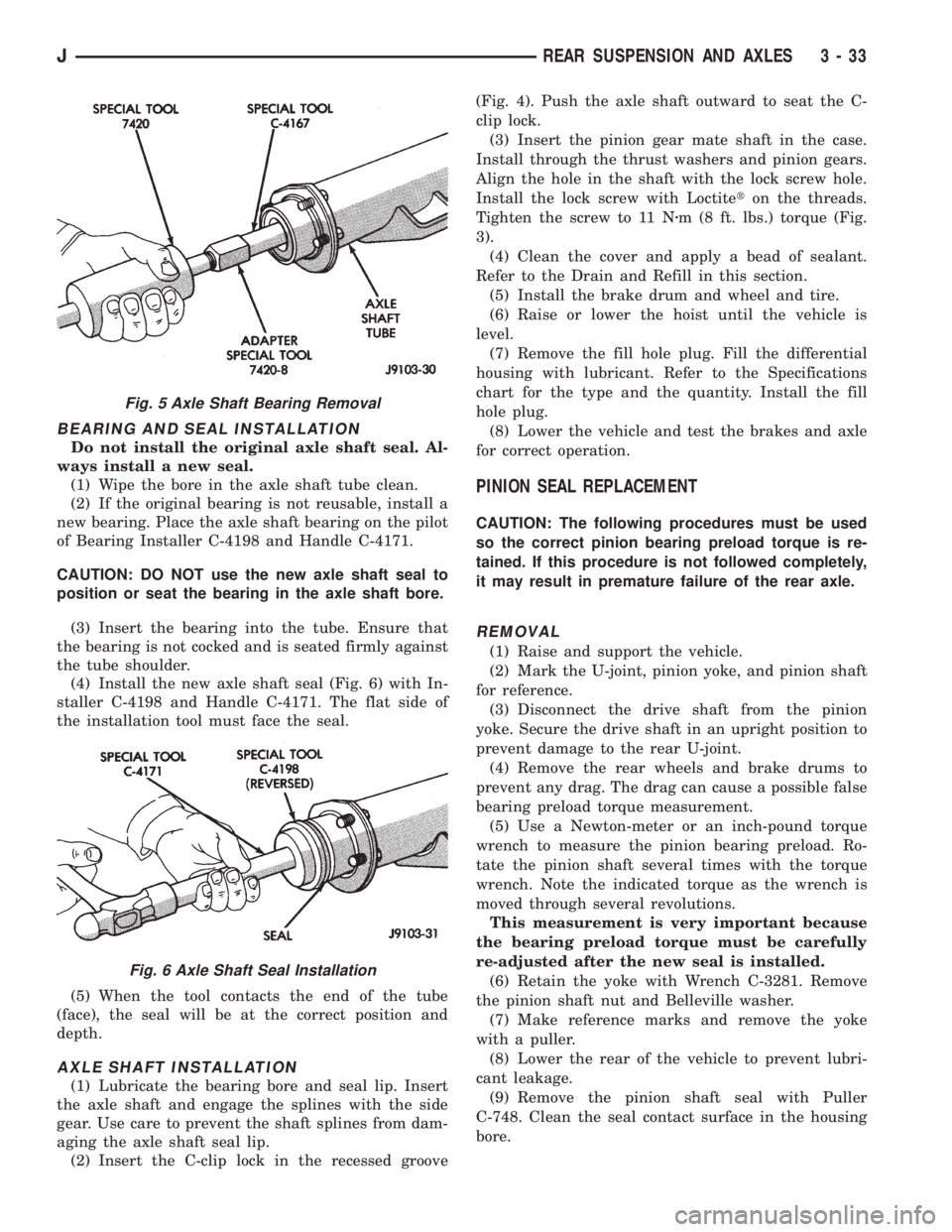
BEARING AND SEAL INSTALLATION
Do not install the original axle shaft seal. Al-
ways install a new seal.
(1) Wipe the bore in the axle shaft tube clean.
(2) If the original bearing is not reusable, install a
new bearing. Place the axle shaft bearing on the pilot
of Bearing Installer C-4198 and Handle C-4171.
CAUTION: DO NOT use the new axle shaft seal to
position or seat the bearing in the axle shaft bore.
(3) Insert the bearing into the tube. Ensure that
the bearing is not cocked and is seated firmly against
the tube shoulder.
(4) Install the new axle shaft seal (Fig. 6) with In-
staller C-4198 and Handle C-4171. The flat side of
the installation tool must face the seal.
(5) When the tool contacts the end of the tube
(face), the seal will be at the correct position and
depth.
AXLE SHAFT INSTALLATION
(1) Lubricate the bearing bore and seal lip. Insert
the axle shaft and engage the splines with the side
gear. Use care to prevent the shaft splines from dam-
aging the axle shaft seal lip.
(2) Insert the C-clip lock in the recessed groove(Fig. 4). Push the axle shaft outward to seat the C-
clip lock.
(3) Insert the pinion gear mate shaft in the case.
Install through the thrust washers and pinion gears.
Align the hole in the shaft with the lock screw hole.
Install the lock screw with Loctiteton the threads.
Tighten the screw to 11 Nzm (8 ft. lbs.) torque (Fig.
3).
(4) Clean the cover and apply a bead of sealant.
Refer to the Drain and Refill in this section.
(5) Install the brake drum and wheel and tire.
(6) Raise or lower the hoist until the vehicle is
level.
(7) Remove the fill hole plug. Fill the differential
housing with lubricant. Refer to the Specifications
chart for the type and the quantity. Install the fill
hole plug.
(8) Lower the vehicle and test the brakes and axle
for correct operation.
PINION SEAL REPLACEMENT
CAUTION: The following procedures must be used
so the correct pinion bearing preload torque is re-
tained. If this procedure is not followed completely,
it may result in premature failure of the rear axle.
REMOVAL
(1) Raise and support the vehicle.
(2) Mark the U-joint, pinion yoke, and pinion shaft
for reference.
(3) Disconnect the drive shaft from the pinion
yoke. Secure the drive shaft in an upright position to
prevent damage to the rear U-joint.
(4) Remove the rear wheels and brake drums to
prevent any drag. The drag can cause a possible false
bearing preload torque measurement.
(5) Use a Newton-meter or an inch-pound torque
wrench to measure the pinion bearing preload. Ro-
tate the pinion shaft several times with the torque
wrench. Note the indicated torque as the wrench is
moved through several revolutions.
This measurement is very important because
the bearing preload torque must be carefully
re-adjusted after the new seal is installed.
(6) Retain the yoke with Wrench C-3281. Remove
the pinion shaft nut and Belleville washer.
(7) Make reference marks and remove the yoke
with a puller.
(8) Lower the rear of the vehicle to prevent lubri-
cant leakage.
(9) Remove the pinion shaft seal with Puller
C-748. Clean the seal contact surface in the housing
bore.
Fig. 5 Axle Shaft Bearing Removal
Fig. 6 Axle Shaft Seal Installation
JREAR SUSPENSION AND AXLES 3 - 33
Page 128 of 2198
gear mate shaft.Do not remove the feeler
gauges, inspect the axle shaft with the feeler
gauge inserted behind the side gear.If the end of
the axle shaft is not contacting the pinion gear mate
shaft, the side gear clearance is acceptable.
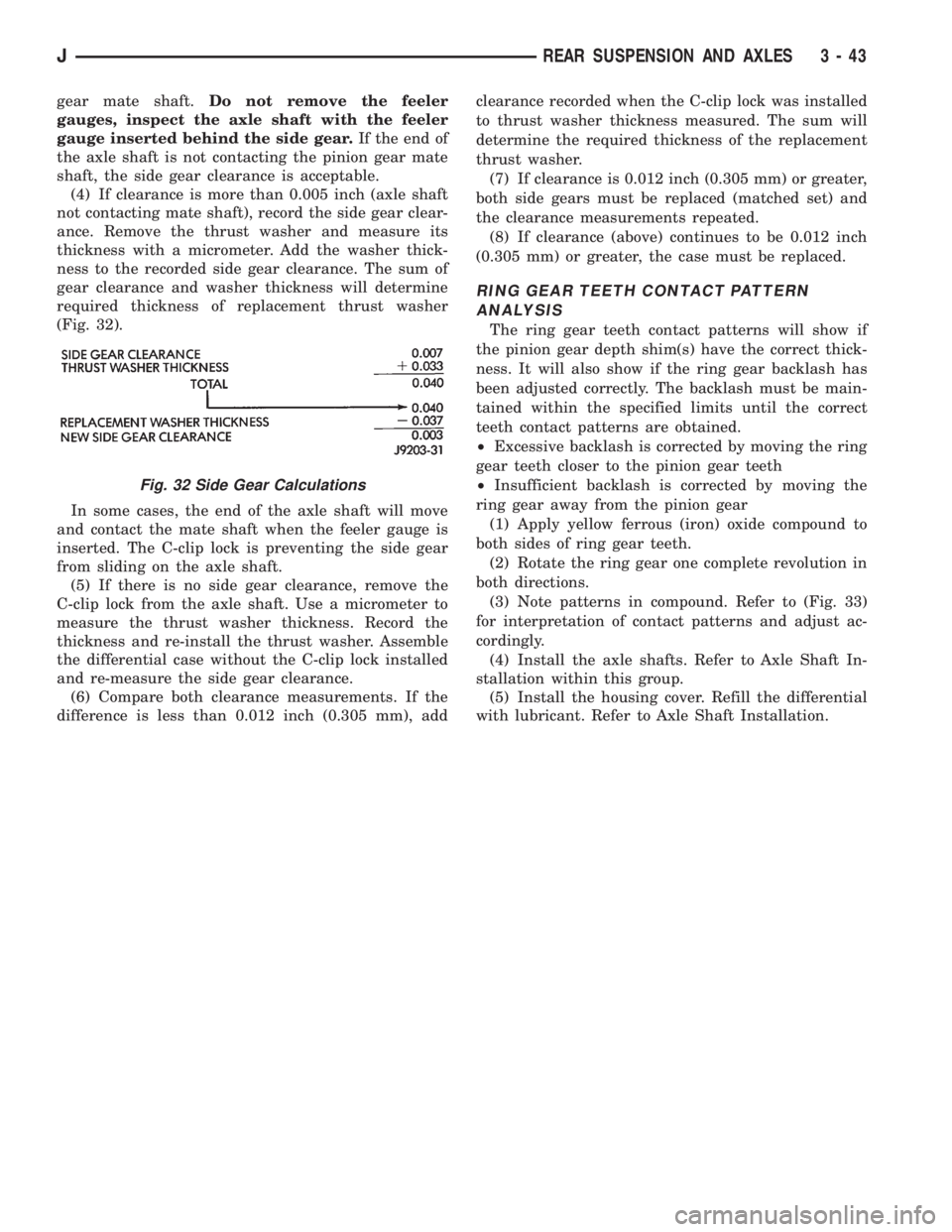
(4) If clearance is more than 0.005 inch (axle shaft
not contacting mate shaft), record the side gear clear-
ance. Remove the thrust washer and measure its
thickness with a micrometer. Add the washer thick-
ness to the recorded side gear clearance. The sum of
gear clearance and washer thickness will determine
required thickness of replacement thrust washer
(Fig. 32).
In some cases, the end of the axle shaft will move
and contact the mate shaft when the feeler gauge is
inserted. The C-clip lock is preventing the side gear
from sliding on the axle shaft.
(5) If there is no side gear clearance, remove the
C-clip lock from the axle shaft. Use a micrometer to
measure the thrust washer thickness. Record the
thickness and re-install the thrust washer. Assemble
the differential case without the C-clip lock installed
and re-measure the side gear clearance.
(6) Compare both clearance measurements. If the
difference is less than 0.012 inch (0.305 mm), addclearance recorded when the C-clip lock was installed
to thrust washer thickness measured. The sum will
determine the required thickness of the replacement
thrust washer.
(7) If clearance is 0.012 inch (0.305 mm) or greater,
both side gears must be replaced (matched set) and
the clearance measurements repeated.
(8) If clearance (above) continues to be 0.012 inch
(0.305 mm) or greater, the case must be replaced.
RING GEAR TEETH CONTACT PATTERN
ANALYSIS
The ring gear teeth contact patterns will show if
the pinion gear depth shim(s) have the correct thick-
ness. It will also show if the ring gear backlash has
been adjusted correctly. The backlash must be main-
tained within the specified limits until the correct
teeth contact patterns are obtained.
²Excessive backlash is corrected by moving the ring
gear teeth closer to the pinion gear teeth
²Insufficient backlash is corrected by moving the
ring gear away from the pinion gear
(1) Apply yellow ferrous (iron) oxide compound to
both sides of ring gear teeth.
(2) Rotate the ring gear one complete revolution in
both directions.
(3) Note patterns in compound. Refer to (Fig. 33)
for interpretation of contact patterns and adjust ac-
cordingly.
(4) Install the axle shafts. Refer to Axle Shaft In-
stallation within this group.
(5) Install the housing cover. Refill the differential
with lubricant. Refer to Axle Shaft Installation.
Fig. 32 Side Gear Calculations
JREAR SUSPENSION AND AXLES 3 - 43
Page 130 of 2198
TRAC-LOK DIFFERENTIAL
OPERATION
In a conventional differential, the torque applied to
the ring gear is transmitted to the axle shafts through
the differential gears. During normal operation, the
torque transmitted to each wheel is equal at all times.
However, if one wheel spins, the opposite wheel will
generate only as much torque as the spinning wheel.
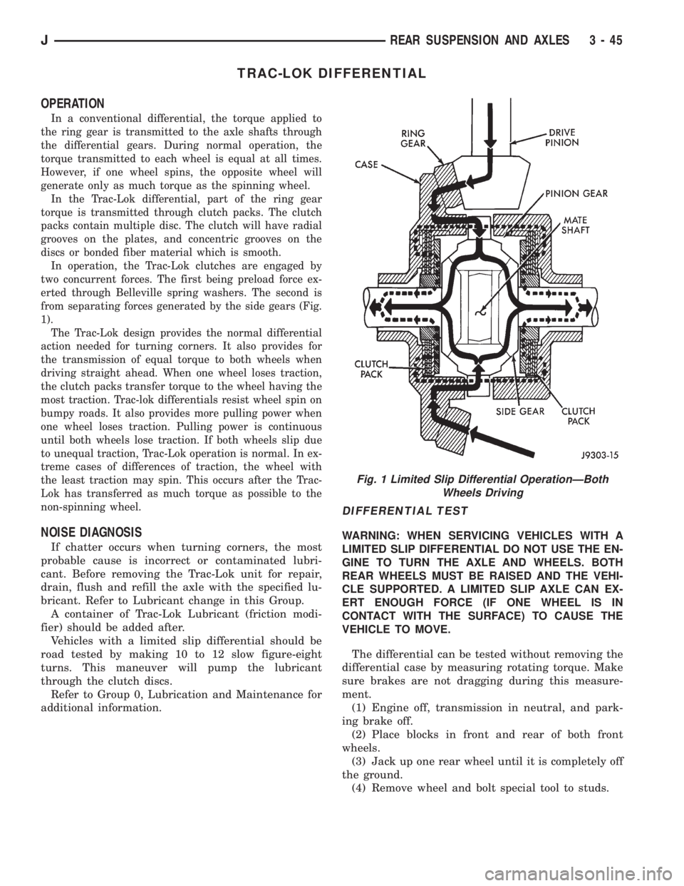
In the Trac-Lok differential, part of the ring gear
torque is transmitted through clutch packs. The clutch
packs contain multiple disc. The clutch will have radial
grooves on the plates, and concentric grooves on the
discs or bonded fiber material which is smooth.
In operation, the Trac-Lok clutches are engaged by
two concurrent forces. The first being preload force ex-
erted through Belleville spring washers. The second is
from separating forces generated by the side gears (Fig.
1).
The Trac-Lok design provides the normal differential
action needed for turning corners. It also provides for
the transmission of equal torque to both wheels when
driving straight ahead. When one wheel loses traction,
the clutch packs transfer torque to the wheel having the
most traction. Trac-lok differentials resist wheel spin on
bumpy roads. It also provides more pulling power when
one wheel loses traction. Pulling power is continuous
until both wheels lose traction. If both wheels slip due
to unequal traction, Trac-Lok operation is normal. In ex-
treme cases of differences of traction, the wheel with
the least traction may spin. This occurs after the Trac-
Lok has transferred as much torque as possible to the
non-spinning wheel.
NOISE DIAGNOSIS
If chatter occurs when turning corners, the most
probable cause is incorrect or contaminated lubri-
cant. Before removing the Trac-Lok unit for repair,
drain, flush and refill the axle with the specified lu-
bricant. Refer to Lubricant change in this Group.
A container of Trac-Lok Lubricant (friction modi-
fier) should be added after.
Vehicles with a limited slip differential should be
road tested by making 10 to 12 slow figure-eight
turns. This maneuver will pump the lubricant
through the clutch discs.
Refer to Group 0, Lubrication and Maintenance for
additional information.
DIFFERENTIAL TEST
WARNING: WHEN SERVICING VEHICLES WITH A
LIMITED SLIP DIFFERENTIAL DO NOT USE THE EN-
GINE TO TURN THE AXLE AND WHEELS. BOTH
REAR WHEELS MUST BE RAISED AND THE VEHI-
CLE SUPPORTED. A LIMITED SLIP AXLE CAN EX-
ERT ENOUGH FORCE (IF ONE WHEEL IS IN
CONTACT WITH THE SURFACE) TO CAUSE THE
VEHICLE TO MOVE.
The differential can be tested without removing the
differential case by measuring rotating torque. Make
sure brakes are not dragging during this measure-
ment.
(1) Engine off, transmission in neutral, and park-
ing brake off.
(2) Place blocks in front and rear of both front
wheels.
(3) Jack up one rear wheel until it is completely off
the ground.
(4) Remove wheel and bolt special tool to studs.
Fig. 1 Limited Slip Differential OperationÐBoth
Wheels Driving
JREAR SUSPENSION AND AXLES 3 - 45
Page 147 of 2198
BRAKE FLUIDÐBRAKE BLEEDINGÐBRAKELINES AND HOSES
INDEX
page page
Brake Bleeding (With ABS Brakes)............ 11
Brake Bleeding (With Standard Brakes)......... 11
Brake Bleeding Recommendations............ 10
Brake Fluid Contamination.................. 10Brake Fluid Level......................... 10
Brakeline Charts.......................... 12
Brakelines and Hoses...................... 12
Recommended Brake Fluid.................. 10
RECOMMENDED BRAKE FLUID
Recommended brake fluid for Jeep vehicles is Mo-
par brake fluid, or an equivalent fluid meeting SAE
J1703 and DOT 3 standards. The recommendation
applies to models with standard or ABS brakes.
Use new brake fluid to top off the master cyl-
inder or refill the system. Never use reclaimed
fluid, fluid not meeting the SAE/DOT standards
or fluid from an unsealed container. Do not use
fluid from any container that has been left
open for any length of time. Fluid in open con-
tainers can absorb moisture.
BRAKE FLUID LEVEL
Always clean the master cylinder reservoir and
cover or cap before adding fluid. This avoids having
dirt from the cap or reservoir exterior fall into the
fluid.
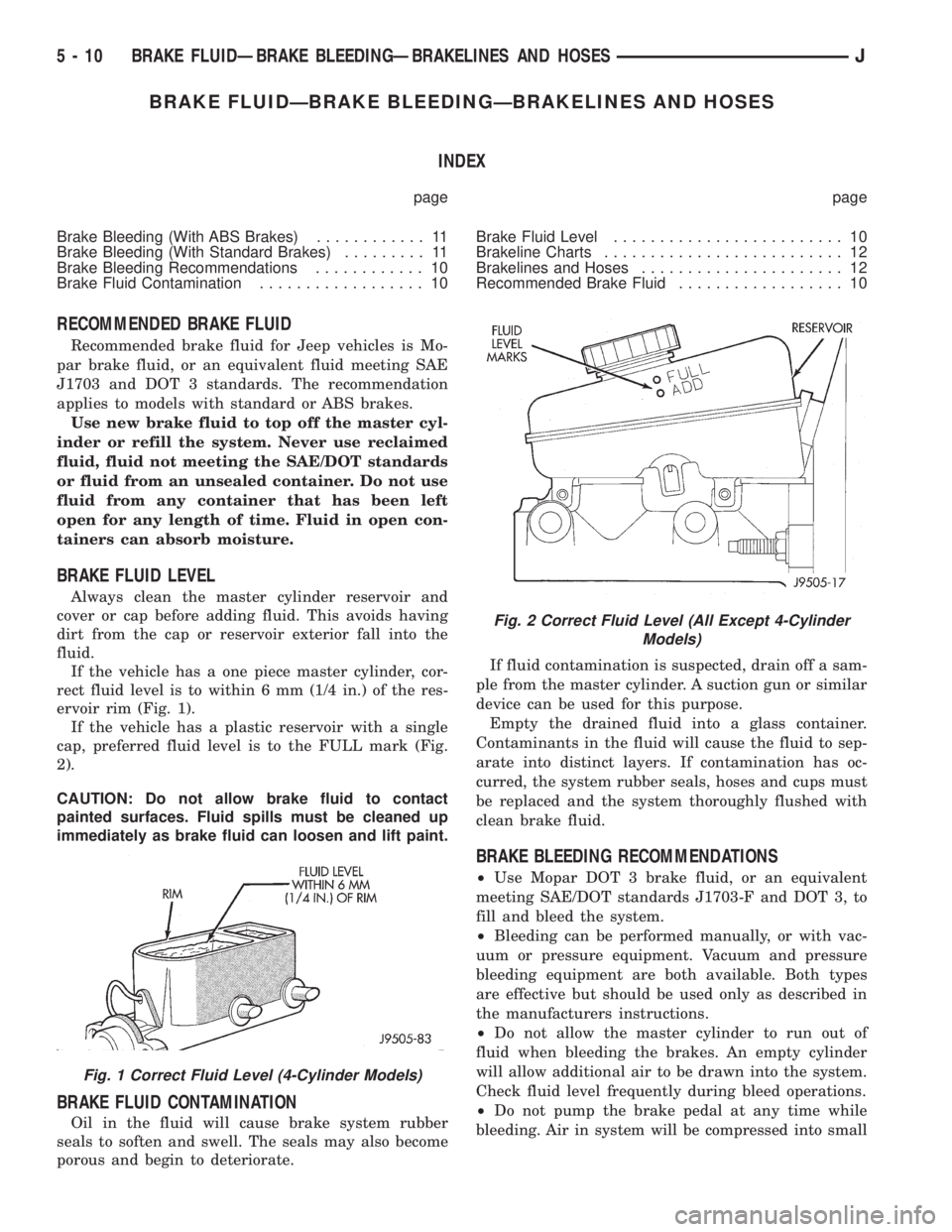
If the vehicle has a one piece master cylinder, cor-
rect fluid level is to within 6 mm (1/4 in.) of the res-
ervoir rim (Fig. 1).
If the vehicle has a plastic reservoir with a single
cap, preferred fluid level is to the FULL mark (Fig.
2).
CAUTION: Do not allow brake fluid to contact
painted surfaces. Fluid spills must be cleaned up
immediately as brake fluid can loosen and lift paint.
BRAKE FLUID CONTAMINATION
Oil in the fluid will cause brake system rubber
seals to soften and swell. The seals may also become
porous and begin to deteriorate.If fluid contamination is suspected, drain off a sam-
ple from the master cylinder. A suction gun or similar
device can be used for this purpose.
Empty the drained fluid into a glass container.
Contaminants in the fluid will cause the fluid to sep-
arate into distinct layers. If contamination has oc-
curred, the system rubber seals, hoses and cups must
be replaced and the system thoroughly flushed with
clean brake fluid.
BRAKE BLEEDING RECOMMENDATIONS
²Use Mopar DOT 3 brake fluid, or an equivalent
meeting SAE/DOT standards J1703-F and DOT 3, to
fill and bleed the system.
²Bleeding can be performed manually, or with vac-
uum or pressure equipment. Vacuum and pressure
bleeding equipment are both available. Both types
are effective but should be used only as described in
the manufacturers instructions.
²Do not allow the master cylinder to run out of
fluid when bleeding the brakes. An empty cylinder
will allow additional air to be drawn into the system.
Check fluid level frequently during bleed operations.
²Do not pump the brake pedal at any time while
bleeding. Air in system will be compressed into small
Fig. 1 Correct Fluid Level (4-Cylinder Models)
Fig. 2 Correct Fluid Level (All Except 4-Cylinder
Models)
5 - 10 BRAKE FLUIDÐBRAKE BLEEDINGÐBRAKELINES AND HOSESJ
Page 208 of 2198
CLUTCH
CONTENTS
page page
CLUTCH DIAGNOSIS...................... 3
CLUTCH SERVICE....................... 10GENERAL INFORMATION.................. 1
GENERAL INFORMATION
INDEX
page page
Clutch Components........................ 1
Clutch Linkage Fluid........................ 1Clutch Operation........................... 2
Hydraulic Linkage Components................ 1
CLUTCH COMPONENTS
The clutch mechanism in XJ/YJ models consists of
a single, dry-type disc and a diaphragm style clutch
cover. A hydraulic linkage is used to operate the
clutch release bearing and fork.
A needle-type pilot bearing supports the transmis-
sion input shaft in the crankshaft. A sleeve type re-
lease bearing is used to engage and disengage the
clutch cover pressure plate.
The release bearing is operated by a release fork in
the clutch housing. The fork pivots on a ball stud
mounted in the housing. The release fork is actuated
by a hydraulic slave cylinder mounted in the hous-
ing. The slave cylinder is operated by a clutch master
cylinder mounted on the dash panel. The cylinder
push rod is connected to the clutch pedal.
The clutch disc has cushion springs in the disc hub.
The clutch disc facing is riveted to the hub. The fac-
ing is made from a non-asbestos material. The clutch
cover pressure plate is a diaphragm type with a one-
piece spring and multiple release fingers. The pres-
sure plate release fingers are preset during
manufacture and are not adjustable.
HYDRAULIC LINKAGE COMPONENTS
The hydraulic linkage consists of a clutch master
cylinder with integral reservoir, a clutch slave cylin-
der and an interconnecting fluid line.The clutch master cylinder push rod is connected to
the clutch pedal. The slave cylinder push rod is con-
nected to the clutch release fork. The master cylinder
is mounted on the driver side of the dash panel ad-
jacent to the brake master cylinder and booster as-
sembly. This positioning is similar for both left and
right hand drive models.
CLUTCH LINKAGE FLUID
The integral clutch master cylinder reservoir, slave
cylinder and fluid lines are prefilled with fluid prior
to assembly operations.
The hydraulic system should not require additional
fluid under normal circumstances. In fact,the reser-
voir fluid level will actually increase as normal
clutch wear occurs. For this reason, it is impor-
tant to avoid overfilling, or removing fluid from
the reservoir. This will cause clutch release
problems.
If inspection or diagnosis indicates additional fluid
may be needed, use Mopar brake fluid, or an equiv-
alent meeting standards SAE J1703 and DOT 3. Do
not use any other type of fluid.
JCLUTCH 6 - 1
Page 221 of 2198
CLUTCH HYDRAULIC LINKAGE INSTALLATION
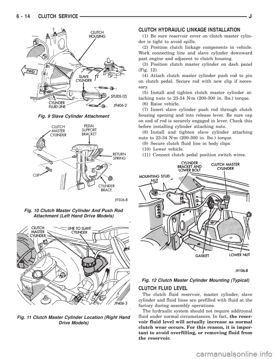
(1) Be sure reservoir cover on clutch master cylin-
der is tight to avoid spills.
(2) Position clutch linkage components in vehicle.
Work connecting line and slave cylinder downward
past engine and adjacent to clutch housing.
(3) Position clutch master cylinder on dash panel
(Fig. 12).
(4) Attach clutch master cylinder push rod to pin
on clutch pedal. Secure rod with new clip if neces-
sary.
(5) Install and tighten clutch master cylinder at-
taching nuts to 23-34 Nzm (200-300 in. lbs.) torque.
(6) Raise vehicle.
(7) Insert slave cylinder push rod through clutch
housing opening and into release lever. Be sure cap
on end of rod is securely engaged in lever. Check this
before installing cylinder attaching nuts.
(8) Install and tighten slave cylinder attaching
nuts to 23-34 Nzm (200-300 in. lbs.) torque.
(9) Secure clutch fluid line in body clips.
(10) Lower vehicle.
(11) Connect clutch pedal position switch wires.
CLUTCH FLUID LEVEL
The clutch fluid reservoir, master cylinder, slave
cylinder and fluid lines are prefilled with fluid at the
factory during assembly operations.
The hydraulic system should not require additional
fluid under normal circumstances. In fact,the reser-
voir fluid level will actually increase as normal
clutch wear occurs. For this reason, it is impor-
tant to avoid overfilling, or removing fluid from
the reservoir.
Fig. 9 Slave Cylinder Attachment
Fig. 10 Clutch Master Cylinder And Push Rod
Attachment (Left Hand Drive Models)
Fig. 11 Clutch Master Cylinder Location (Right Hand
Drive Models)
Fig. 12 Clutch Master Cylinder Mounting (Typical)
6 - 14 CLUTCH SERVICEJ
Page 230 of 2198

EXAMPLES:
²If the lamp (Figs. 5 or 6) flashes 1 time, pauses
and flashes 2 more times, a flashing Diagnostic Trou-
ble Code (DTC) number 12 is indicated. If this code is
observed, it is indicating that the battery has been
disconnected within the last 50 key-on cycles. It
could also indicate that battery voltage has been dis-
connected to the PCM. In either case, other DTC's
may have been erased.
²If the lamp flashes 1 time, pauses and flashes 7
more times, a flashing Diagnostic Trouble Code
(DTC) number 17 is indicated.
²If the lamp flashes 3 times, pauses and flashes 5
more times, a flashing Diagnostic Trouble Code
(DTC) number 35 is indicated.
After any stored DTC information has been ob-
served, the display will end with a flashing DTC
number 55. This will indicate the end of all stored in-
formation.
ERASING TROUBLE CODES
After the problem has been repaired, the DRB scan
tool must be used to erase a DTC. Refer to the ap-
propriate Powertrain Diagnostic Procedures service
manual for operation of the DRB scan tool.
DRB SCAN TOOL
For operation of the DRB scan tool, refer to the ap-
propriate Powertrain Diagnostic Procedures service
manual.
PRELIMINARY CHECKS
ENGINE COOLING SYSTEM OVERHEATING
Establish what driving conditions caused the com-
plaint. Abnormal loads on the cooling system such as
the following may be the cause.
1. PROLONGED IDLE, VERY HIGH AMBIENT
TEMPERATURE, SLIGHT TAIL WIND AT IDLE,
SLOW TRAFFIC, TRAFFIC JAMS, HIGH
SPEED, OR STEEP GRADES:
Driving techniques that avoid overheating are:
²Idle with A/C off when temperature gauge is at
end of normal range.
²Increasing engine speed for more air flow is recom-
mended.
2. TRAILER TOWING:
Consult Trailer Towing section of owners manual.
Do not exceed limits.
3. AIR CONDITIONING; ADD-ON OR AFTER
MARKET:
A maximum cooling package should have been or-
dered with vehicle if add-on or after market A/C is
installed. If not, maximum cooling system compo-
nents should be installed for model involved per
manufacturer's specifications.
4. RECENT SERVICE OR ACCIDENT REPAIR:
Determine if any recent service has been performed
on vehicle that may effect cooling system. This may
be:
²Engine adjustments (incorrect timing)
²Slipping engine accessory drive belt(s)
²Brakes (possibly dragging)
²Changed parts (incorrect water pump rotating in
wrong direction)
²Reconditioned radiator or cooling system refilling
(possibly under-filled or air trapped in system).
If investigation reveals none of the previous
items as a cause for an engine overheating com-
plaint, refer to following Cooling System Diag-
nosis charts.
These charts are to be used as a quick-reference
only. Refer to the group text for information.
Fig. 7 Data Link ConnectorÐXJ ModelsÐTypical
Fig. 8 Data Link ConnectorÐYJ ModelsÐTypical
JCOOLING SYSTEM DIAGNOSIS 7 - 5
Page 238 of 2198
SERVICE PROCEDURES
INDEX
page page
Auxiliary Electric Cooling FanÐXJ Models with 4.0L
6-Cylinder Engine....................... 35
Coolant................................. 20
Coolant Reserve/Overflow System............. 24
Cooling System Cleaning/Reverse Flushing...... 22
Cooling System Fans...................... 32
Cooling System Hoses..................... 32
Draining Cooling System.................... 21
Radiator Pressure Cap..................... 25
Radiators............................... 26Refilling Cooling System.................... 21
Testing Cooling System for Leaks............. 22
Thermostat.............................. 17
Transmission Oil Coolers.................... 36
Viscous Fan Drive......................... 34
Water Pump Tests......................... 13
Water PumpsÐGeneral Information............ 13
Water PumpsÐRemoval/Installation........... 14
WATER PUMPSÐGENERAL INFORMATION
A centrifugal water pump circulates coolant
through the water jackets, passages, intake manifold,
radiator core, cooling system hoses and heater core.
The pump is driven from the engine crankshaft by a
drive belt on all engines.
The water pump impeller is pressed onto the rear
of a shaft that rotates in bearings pressed into the
housing. The housing has a small hole to allow seep-
age to escape. The water pump seals are lubricated
by the antifreeze in the coolant mixture. No addi-
tional lubrication is necessary.
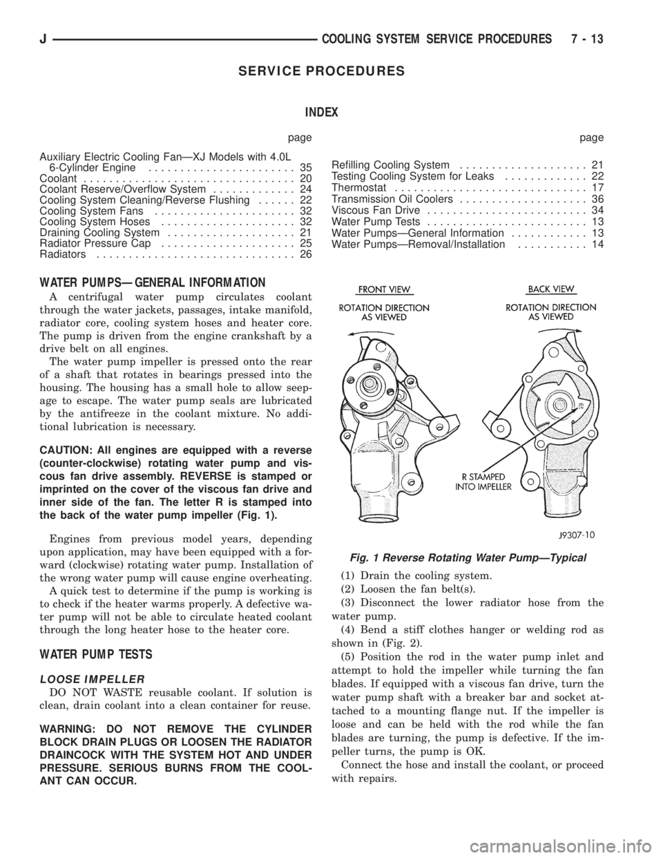
CAUTION: All engines are equipped with a reverse
(counter-clockwise) rotating water pump and vis-
cous fan drive assembly. REVERSE is stamped or
imprinted on the cover of the viscous fan drive and
inner side of the fan. The letter R is stamped into
the back of the water pump impeller (Fig. 1).
Engines from previous model years, depending
upon application, may have been equipped with a for-
ward (clockwise) rotating water pump. Installation of
the wrong water pump will cause engine overheating.
A quick test to determine if the pump is working is
to check if the heater warms properly. A defective wa-
ter pump will not be able to circulate heated coolant
through the long heater hose to the heater core.
WATER PUMP TESTS
LOOSE IMPELLER
DO NOT WASTE reusable coolant. If solution is
clean, drain coolant into a clean container for reuse.
WARNING: DO NOT REMOVE THE CYLINDER
BLOCK DRAIN PLUGS OR LOOSEN THE RADIATOR
DRAINCOCK WITH THE SYSTEM HOT AND UNDER
PRESSURE. SERIOUS BURNS FROM THE COOL-
ANT CAN OCCUR.(1) Drain the cooling system.
(2) Loosen the fan belt(s).
(3) Disconnect the lower radiator hose from the
water pump.
(4) Bend a stiff clothes hanger or welding rod as
shown in (Fig. 2).
(5) Position the rod in the water pump inlet and
attempt to hold the impeller while turning the fan
blades. If equipped with a viscous fan drive, turn the
water pump shaft with a breaker bar and socket at-
tached to a mounting flange nut. If the impeller is
loose and can be held with the rod while the fan
blades are turning, the pump is defective. If the im-
peller turns, the pump is OK.
Connect the hose and install the coolant, or proceed
with repairs.
Fig. 1 Reverse Rotating Water PumpÐTypical
JCOOLING SYSTEM SERVICE PROCEDURES 7 - 13