1995 JEEP CHEROKEE hood open
[x] Cancel search: hood openPage 475 of 2198
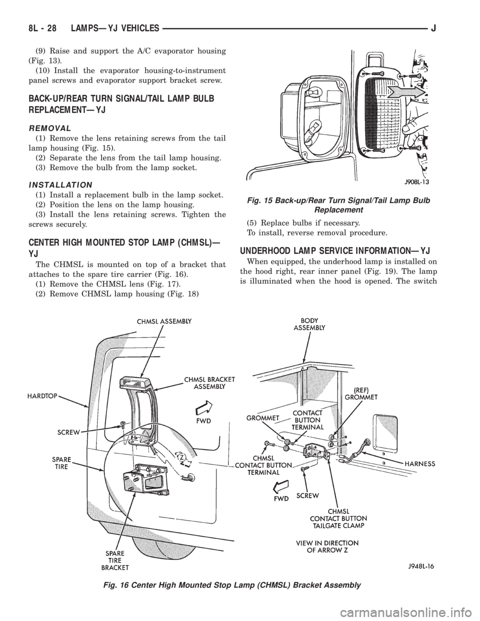
(9) Raise and support the A/C evaporator housing
(Fig. 13).
(10) Install the evaporator housing-to-instrument
panel screws and evaporator support bracket screw.
BACK-UP/REAR TURN SIGNAL/TAIL LAMP BULB
REPLACEMENTÐYJ
REMOVAL
(1) Remove the lens retaining screws from the tail
lamp housing (Fig. 15).
(2) Separate the lens from the tail lamp housing.
(3) Remove the bulb from the lamp socket.
INSTALLATION
(1) Install a replacement bulb in the lamp socket.
(2) Position the lens on the lamp housing.
(3) Install the lens retaining screws. Tighten the
screws securely.
CENTER HIGH MOUNTED STOP LAMP (CHMSL)Ð
YJ
The CHMSL is mounted on top of a bracket that
attaches to the spare tire carrier (Fig. 16).
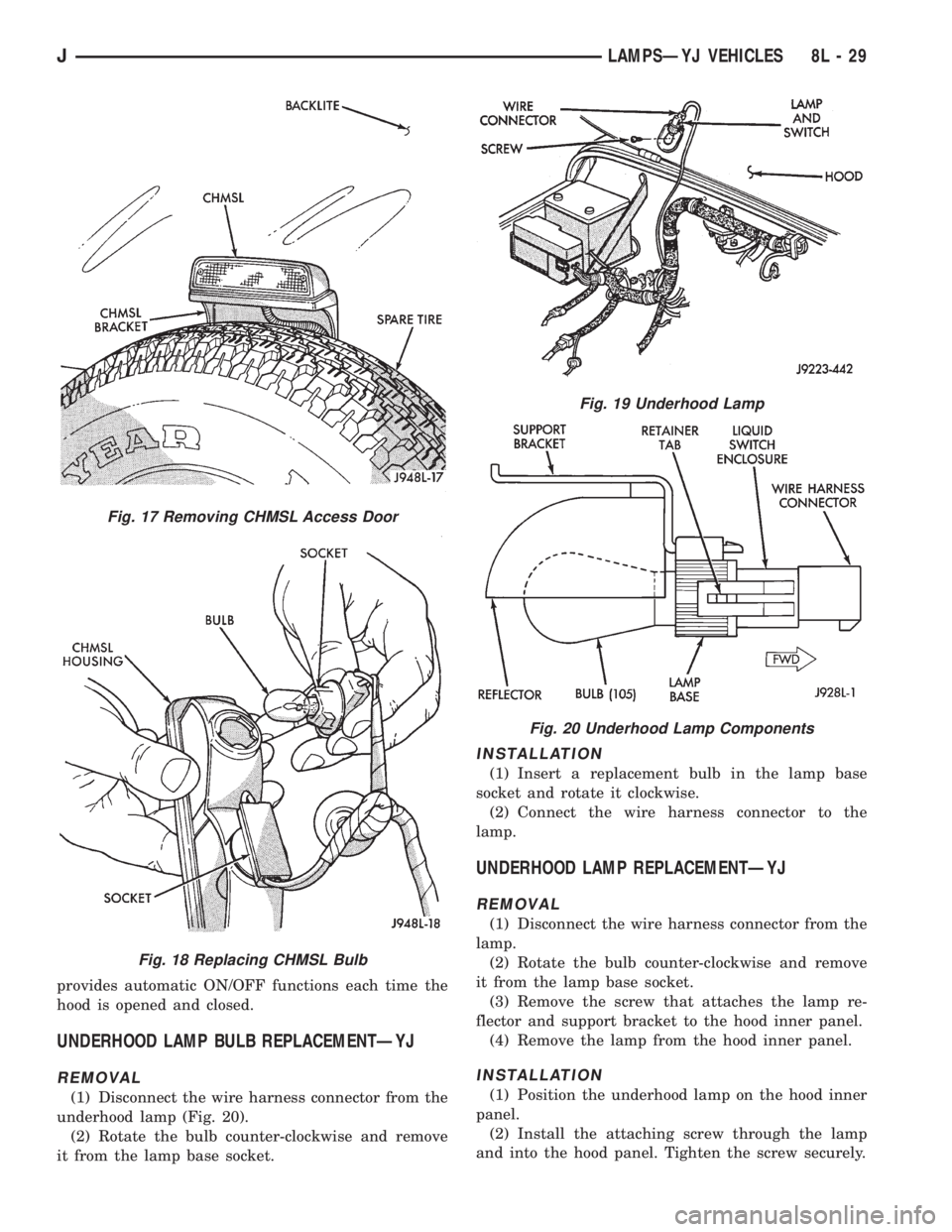
(1) Remove the CHMSL lens (Fig. 17).
(2) Remove CHMSL lamp housing (Fig. 18)(5) Replace bulbs if necessary.
To install, reverse removal procedure.
UNDERHOOD LAMP SERVICE INFORMATIONÐYJ
When equipped, the underhood lamp is installed on
the hood right, rear inner panel (Fig. 19). The lamp
is illuminated when the hood is opened. The switch
Fig. 15 Back-up/Rear Turn Signal/Tail Lamp Bulb
Replacement
Fig. 16 Center High Mounted Stop Lamp (CHMSL) Bracket Assembly
8L - 28 LAMPSÐYJ VEHICLESJ
Page 476 of 2198
provides automatic ON/OFF functions each time the
hood is opened and closed.
UNDERHOOD LAMP BULB REPLACEMENTÐYJ
REMOVAL
(1) Disconnect the wire harness connector from the
underhood lamp (Fig. 20).
(2) Rotate the bulb counter-clockwise and remove
it from the lamp base socket.
INSTALLATION
(1) Insert a replacement bulb in the lamp base
socket and rotate it clockwise.
(2) Connect the wire harness connector to the
lamp.
UNDERHOOD LAMP REPLACEMENTÐYJ
REMOVAL
(1) Disconnect the wire harness connector from the
lamp.
(2) Rotate the bulb counter-clockwise and remove
it from the lamp base socket.
(3) Remove the screw that attaches the lamp re-
flector and support bracket to the hood inner panel.
(4) Remove the lamp from the hood inner panel.
INSTALLATION
(1) Position the underhood lamp on the hood inner
panel.
(2) Install the attaching screw through the lamp
and into the hood panel. Tighten the screw securely.
Fig. 17 Removing CHMSL Access Door
Fig. 18 Replacing CHMSL Bulb
Fig. 19 Underhood Lamp
Fig. 20 Underhood Lamp Components
JLAMPSÐYJ VEHICLES 8L - 29
Page 632 of 2198

INTERIOR LIGHTING
INDEX
page page
Cargo Lamp, Courtesy Lamps and Dome Lamp.... 1
Chime/Buzzer Module....................... 2
Diagram Index............................ 2
General Information........................ 1
Glove Box Lamp........................... 1
Ignition Switch Lamp........................ 1Instrument Panel Illumination Lamps............ 1
Reading Lamps........................... 2
Time Delay Relay.......................... 1
Underhood Lamp.......................... 2
Visor Vanity Mirror Lamps.................... 2
GENERAL INFORMATION
Circuit M1 supplies power to the glove box lamp,
left courtesy lamp, right courtesy lamp, dome lamp,
and cargo lamp. The M1 circuit also connects to the
remote keyless entry module. Circuit M1 is protected
by the ignition off draw (IOD) fuse (fuse 9) in the fuse
block.
Circuit E2 supplies power for the instrument panel
illumination lamps.
INSTRUMENT PANEL ILLUMINATION LAMPS
Circuit E2 from the headlamp switch splices to
supply power to the following illumination lamps:
²Ash receiver lamp
²Cigar lighter lamp
²Transmission range indicator lamp
²Transfer case range indicator lamp
²A/C-Heater switch lamp
²Heated rear window lamp
²Rear wiper switch lamp
²Fog lamp switch lamp
Fuse 19 in the fuse block protects circuit E2. Circuit
Z1 provides ground for all of the illumination lamps
except for the cigar lighter lamp. The cigar lighter
lamp is case grounded.
HELPFUL INFORMATION
Circuit E2 also supplies power to the radio, LCD
relay and the illumination lamps in the instrument
cluster.
IGNITION SWITCH LAMP
The time delay relay is used to allow a time-ON
function for the ignition switch lamp and the courtesy
lamp. Power for the relay is received on the M1
circuit from the IOD fuse (fuse F9) in the fuse block.
Circuit M2 provides ground for the time delay relay
through the right and left door ajar switches and the
headlamp switch. When a door is opened, or the
headlamp switch is moved to the dome lamp position,a ground path is provided for the relay on circuit M2.
This energizes the relay, causing the contacts to close.
When the relay contacts close, power is provided
through the relay to circuit M50. The M50 circuit
supplies current to the ignition switch lamp. Circuit
Z1 provides ground for the lamp.
GLOVE BOX LAMP
Circuit M1 from the IOD fuse (fuse F9) in the fuse
block powers the glove box lamp. A case grounded
switch, in series after the lamp, closes when the glove
box door is opened. The switch completes a path to
ground on circuit Z1.
CARGO LAMP, COURTESY LAMPS AND DOME
LAMP
Circuit M1 from the IOD fuse (fuse F9) in the fuse
block supplies power to the cargo, courtesy lamps and
dome lamp. This circuit is HOT at all times. The
ground path for the lamp is provided in three differ-
ent ways.
One way is through the door jamb switches. Circuit
M2 connects to the door jamb switches from the cour-
tesy and dome lamps. The switches are connected to
ground circuit Z1. When a door is opened, the plunger
in the switch closes, completing a path to ground.
The second way is through the liftgate switch. Cir-
cuit M2 connects to circuit M4 at the cargo lamp.
Circuit M4 connects to the liftgate switch. The lift-
gate switch connects to ground circuit Z1. When the
lift gate opens, the plunger in the switch closes, com-
pleting a path to ground.
The third ground path is through the headlamp
switch. Circuit M2 is spliced in with the headlamp
switch. When the operator turns the headlamp switch
to the dome lamp ON position, a ground path is
provided through the switch.
J8W-44 INTERIOR LIGHTINGÐXJ VEHICLES 8W - 44 - 1
Page 633 of 2198
READING LAMPS
Circuit M1 from the IOD fuse (fuse F9) in the fuse
block supplies power to the reading lamps. Circuit
M1 is HOT at all times. When the operator depresses
the reading lamp, the reading lamp switch closes and
supplies ground on circuit Z1.
VISOR VANITY MIRROR LAMPS
Circuit M1 from the IOD fuse (fuse F9) in the fuse
block supplies power to the vanity lamps. Circuit M1
is HOT at all times. When the vanity lamps switch
closes, voltage flows to vanity mirror lamps. The van-
ity mirror is case grounded.
UNDERHOOD LAMP
Circuit A6 from fuse 16 in the Power Distribution
Center (PDC) supplies battery voltage for the under-
hood lamp. A mercury switch, in series after the
lamp, connects the lamp to ground on circuit Z1.
When the hood is raised, mercury inside the switch
moves to a position where it connects circuit M1 to
ground circuit Z1, illuminating the lamp.
CHIME/BUZZER MODULE
The buzzer or optional chime module sounds an au-
dible warning tone. The tone sounds for seat belt
warning and when the ignition key is in the ignition
switch while the drivers door is open. The tone also
sounds when the ignition key is in the ON position
while the drivers side seat belt is not buckled. Lastly,
the tone sounds when the headlamps are ON when
the ignition is OFF. Refer to Group 8U for system op-
eration.
When the ignition switch is in the RUN or START
position, circuit F87 from fuse 17 in the fuse block
supplies power to the chime/buzzer module. Circuit
A21 from the ignition switch supplies power to fuse
17.
Circuit L7 from fuse 15 in the fuse block also sup-
plies power to the chime/buzzer module. Circuit A3
from fuse 5 in the Power Distribution Center (PDC)
powers fuse 15.
When the parking lamps or headlamps are ON, the
headlamp switch connects circuit G26 with the driv-
ers side door jamb switch. Circuit G26 also connects
to the key-in switch. Circuit M11 connects the key-in
switch to the chime/buzzer module and the headlamp
switch.
If the headlamps are ON, and the drivers door
opens, ground for the chime/buzzer is on circuit C26
from the headlamp switch through the door jamb
switch to circuit Z1.
If the headlamps are OFF with the key in the ig-
nition while the drivers side door is open, ground forthe chime/buzzer is supplied through the key-in
switch. The ground path is over circuit M11, through
the closed key-in switch to circuit C26. From circuit
C26, the ground path continues through the drivers
door jamb switch to circuit Z1.
Circuit G11 from the buzzer powers the seat belt
warning lamp in the instrument cluster. Circuit Z1
at the instrument cluster provides ground for the
lamp.
Circuit G10 from the buzzer connects to the seat
belt switch. When the seat belt switch closes a path
to ground is completed on circuit Z1 and the tone
sounds momentarily.
Circuit Z1 also grounds the chime\buzzer module.
HELPFUL INFORMATION
Circuit F87 also powers the instrument cluster and
the headlamp delay module.
DIAGRAM INDEX
Component Page
Cargo Lamp............................8W-44-6
Chime/Buzzer Module......................8W-44-3
Courtesy Lamps.........................8W-44-5
Dome Lamp............................8W-44-7
Door Jamb Switches.....................8W-44-10
Fuse 3 (PDC).........................8W-44-4, 6
Fuse 5 (PDC).........................8W-44-3, 8
Fuse 6 (PDC)...........................8W-44-3
Fuse 9 (Fuse Block).....................8W-44-4, 6
Fuse 15 (Fuse Block)....................8W-44-3, 8
Fuse 16 (PDC)........................8W-44-4, 6
Fuse 17 (Fuse Block)......................8W-44-3
Fuse 19 (Fuse Block)......................8W-44-8
Glove Box Lamp and Switch.................8W-44-5
Headlamp Switch...................8W-44-3, 4, 5, 8
Headlamp Delay Module....................8W-44-4
Headlamp Delay Relay.....................8W-44-3
Ignition Switch..........................8W-44-3
Instrument Cluster........................8W-44-3
Instrument Panel Illumination Lamps..........8W-44-8, 9
Intermittent Wiper Control Module.............8W-44-4
Key-In Switch...........................8W-44-4
Liftgate Switch..........................8W-44-6
Reading Lamps..........................8W-44-7
Remote Keyless Entry Module................8W-44-7
Seat Belt Switch.........................8W-44-3
Telltale Connector (Instrument Cluster)...........8W-44-3
Time Delay Relay........................8W-44-4
Underhood Lamp.........................8W-44-4
Vanity Lamps...........................8W-44-7
8W - 44 - 2 8W-44 INTERIOR LIGHTINGÐXJ VEHICLESJ
Page 780 of 2198
CONNECTOR LOCATIONS
GENERAL INFORMATION
This section provides illustrations identifying com-
ponent and connector locations in the vehicle. A con-nector index is provided. Use the wiring diagrams in
each section for connector number identification. Re-
fer to the index for the proper figure number.
CONNECTOR LOCATIONS
Connector # Color Location Fig.
C101......BK ...Front of Left Fender Side Shield . . .1, 2
C102......BK ...Bottom Right of Radiator Closure
Panel....................8
C103......BK ...Near Left Side of Radiator......2,8
C104......BK ...Left Fender Side Shield
C105......BK ...Bottom of Left Fender Side Shield . . .2
C106......BK ...Left Fender Side Shield, Near PCM .1, 2
C107......BK ...OnABSPump Motor...........2
C108......BK ...Right Rear Corner of Engine
Compartment.............2,3
C109......BK ...Center of Dash Panel.........1,4
C110......BK ...Center of I.P., Below ABS Control
Module...............13, 14
C111......BK ...Left of Steering Column.........14
C112......BK ...AtABSControl Module.........13
C113......BK ...InHarness, Near ABS Control
Module.................13
C114......BK ...Center of I.P., Below ABS Control
Module.................14
C115......BK ...Near ABS Control Module.......14
C116......BK ...Below ABS Control Module.......14
C117......BK ...Rear of Intake Manifold........6,7
C118......BK ...OnThrottle Body............6,7
C119......BK ...Bottom Left Front of Cylinder
Block..................6,7
C120......BK ...OnThrottle Body............6,7
C121......GY ...Rear of Intake Manifold........6,7
C122......BK ...AtThermostat Housing........6,7
C123......BK ...Injector No. 1..............6,7
C124......BK ...Injector No. 2..............6,7
C125......BK ...Injector No. 3..............6,7
C126......BK ...Injector No. 4..............6,7
C127......BK ...Injector No. 5................7
C128......BK ...Injector No. 6................7
C129......GN ...Center of Dash Panel.........1,4
C130......BK ...Below Brake Master Cylinder.....1,2
C131......BK ...Distributor................6,7
C132......GN ...Lower Right Side of I.P.
C133......BK ...Right of Blower Motor..........4
C134......GY ...Right of Blower Motor..........4
C135......GY ...Right of Blower Motor..........4
C136......BR ...OnWasher Fluid Reservoir......1,4
C137......BK ...Under Side of Hood..........1,4
C138......BK ...Left of Blower Motor...........4
C139......BK ...Bottom of Washer Fluid Reservoir .3, 4
C140......BK ...Bottom of Washer Fluid Reservoir .3, 4
C141......BK ...InFront of Washer Fluid Reservoir .1, 4
C142......BK ...Between PDC and Blower Motor . .1, 4Connector # Color Location Fig.
C143......BK ...Bottom Front of Right Fender
Side Shield..............1,3
C144......BK ...Front of Right Fender Side Shield . .1, 3
C145......BK ...Front of Right Fender Side Shield . .1, 3
C146......BK ...Right Side of Grille Opening.....1,3
C147......BK ...Below Distributor..............7
C148......BK ...Right Side of Engine..........6,7
C149......BK ...Rear of Generator...........5,6
C150......BK ...Right Rear of Engine...........7
C151......BK ...Right Fender Side Shield.......1,4
C152......GY ...Behind Power Steering Pump......6
C153......BK ...Right Side of Transmission.......21
C154......BK ...Left Side of Radiator Closure Panel . .8
C155......BK ...Left Rear of Radiator Closure Panel . .8
C156......BK ...Behind Lens.................8
C157......BK ...Behind Left Headlamp...........8
C158......BK ...Behind Lens.................8
C159......BK ...Center of Grille Opening.........8
C160......BK ...Behind Lens.................8
C161......BK ...Behind Right Headlamp..........8
C162......BK ...Behind Lens.................8
C163......BK ...Center of Grille Opening.........8
C164......BK ...Right Center of Engine Compartment
C201......BK ...Below Left Side of I.P.........9,14
C202......LG ...Behind Left Kick Panel.........14
C203......BK ...Behind Left Kick Panel.........14
C204......GY ...Behind Left Kick Panel.........14
C205......BK ...Bottom Right of I.P............12
C206......BK ...Bottom Right of I.P............12
C207......BK ...Behind Headlamp Switch........10
C208......BK ...Bottom Right of I.P............12
C209......BK ...OnI.P.Right of Steering Column . . .10
C210......BK ...OnI.P.Right of Steering Column . . .10
C211......BK ...Rear of Radio...............11
C212......BR ...Center of I.P.................10
C213......BK ...Center of I.P.................10
C214......GY ...Right Side of I.P..............13
C215......BK ...Right Side of I.P..............13
C216......GY ...Glove Box.................10
C217......BK ...Bottom Right of I.P............11
C218......RD ...Right Side of I.P...........13, 17
C219......BK ...Bottom Right of I.P............11
C220......BK ...Right Side of I.P..............13
C221......BK ...Right Corner of I.P............13
C222......LG ...Right Corner of I.P............13
C223......BK ...Right Front of Steering Column....14
C224......BK ...Right Front of Steering Column....14
C225......NAT...Below Steering Column.........14
J8W-90 CONNECTOR LOCATIONSÐXJ VEHICLES 8W - 90 - 1
Page 908 of 2198
INTERIOR LIGHTING
INDEX
page page
Cargo Lamp and Dome Lamp................. 1
Chime/Buzzer Module....................... 2
Diagram Index............................ 2
General Information........................ 1
Glove Box Lamp........................... 1Ignition Switch Lamp........................ 1
Instrument Panel Illumination Lamps............ 1
Reading Lamps........................... 1
Underhood Lamp.......................... 1
Visor Vanity Mirror Lamps.................... 1
GENERAL INFORMATION
Circuit M1 supplies power to the glove box lamp,
dome lamp, reading lamps, cargo lamp and vanity
lamps. Circuit M1 is protected by fuse 16 in the
Power Distribution Center (PDC).
Circuit E2 supplies power for the instrument panel
illumination lamps.
INSTRUMENT PANEL ILLUMINATION LAMPS
Circuit E2 from the headlamp switch splices to
supply power to the following illumination lamps:
²Ash receiver lamp
²Cigar lighter lamp
²Transmission range indicator lamp
²Transfer case range indicator lamp
²A/C-Heater switch lamp
²Heated rear window switch lamp
²Rear wiper switch lamp
²Fog lamp switch lamp
Fuse 25 in the fuse block protects circuit E2. Cir-
cuit Z1 provides ground for all of the illumination
lamps except for the cigar lighter lamp. The cigar
lighter lamp is case grounded.
HELPFUL INFORMATION
Circuit E2 also supplies power to the radio, LCD
relay and the illumination lamps in the instrument
cluster.
IGNITION SWITCH LAMP
Circuit M50 supplies voltage to the ignition switch
lamp. Circuit Z1 provides ground for the lamp.
GLOVE BOX LAMP
Circuit M1 from fuse 16 in the Power Distribution
Center (PDC) powers the glove box lamp. A case
grounded switch, in series after the lamp, closes
when the glove box door is opened. The switch com-
pletes a path to ground on circuit Z1.
CARGO LAMP AND DOME LAMP
Circuit M1 from fuse 16 in the Power Distribution
Center (PDC) supplies power to the cargo lamp anddome lamp. The M1 circuit is HOT at all times. The
ground path for the lamp is provided in three differ-
ent ways.
One way is through the door jamb switches. Circuit
M2 connects to the door jamb switches to the dome
lamp and cargo lamp. The switches are connected to
ground circuit Z1. When a door is opened, the
plunger in the switch closes, completing a path to
ground.
The second way is through the liftgate switch. Cir-
cuit G71 connects to circuit M2 at the cargo lamp
connector. Circuit G71 connects to the liftgate switch.
The liftgate switch connects to ground circuit Z1.
When the lift gate opens, the plunger in the switch
closes, completing a path to ground.
The third ground path is through the headlamp
switch. Circuit M2 is spliced in with the headlamp
switch. When the operator turns the headlamp
switch to the dome lamp ON position, a ground path
is provided through the switch.
READING LAMPS
Circuit M1 from fuse 16 in the Power Distribution
Center (PDC) supplies power to the reading lamps.
Circuit M1 is HOT at all times. When the operator
depresses the reading lamp, the reading lamp switch
closes and supplies ground on circuit Z1.
VISOR VANITY MIRROR LAMPS
Circuit M1 from fuse 16 in the Power Distribution
Center (PDC) supplies power to the vanity lamps.
Circuit M1 is HOT at all times. When the vanity
lamps switch closes, voltage flows to vanity mirror
lamps. The vanity mirror is case grounded.
UNDERHOOD LAMP
Circuit A7 from fuse 16 in the Power Distribution
Center (PDC) supplies battery voltage for the under-
hood lamp. A mercury switch, in series after the
lamp, connects the lamp to ground on circuit Z1.
When the hood is raised, mercury inside the switch
moves to a position where it connects circuit M1 to
ground circuit Z1, illuminating the lamp.
J8W-44 INTERIOR LIGHTINGÐXJ-RHD 8W - 44 - 1
Page 909 of 2198
CHIME/BUZZER MODULE
The buzzer or optional chime module sounds an au-
dible warning tone. The tone sounds for seat belt
warning and when the ignition key is in the ignition
switch while the drivers door is open. The tone also
sounds when the ignition key is in the ON position
while the drivers side seat belt is not buckled. Lastly,
the tone sounds when the headlamps are ON when
the ignition is OFF. Refer to Group 8U for system op-
eration.
When the ignition switch is in the RUN or START
position, fuse F87 from fuse 26 in the fuse block sup-
plies power to the chime/buzzer module. Circuit A21
from the ignition switch supplies power to fuse 26.
Circuit L7 from fuse 9 in the fuse block also sup-
plies power to the chime/buzzer module. Circuit A3
from fuse 5 in the Power Distribution Center (PDC)
powers fuse 9.
When the parking lamps or headlamps are ON, the
headlamp switch connects circuit G26 with the driv-
ers side door jamb switch. Circuit G26 also connects
to the key-in switch. Circuit M11 connects the key-in
switch to the chime module and the headlamp
switch.
If the headlamps are ON, and the drivers door
opens, ground for the chime/buzzer is on circuit C26
from the headlamp switch through the door jamb
switch to circuit Z1.
If the headlamps are OFF with the key in the ig-
nition while the drivers side door is open, ground for
the chime/buzzer is supplied through the key-in
switch. The ground path is over circuit M11, through
the closed key-in switch to circuit C26. From circuit
C26, the ground path continues through the drivers
door jamb switch to circuit Z1.
Circuit G11 from the buzzer powers the seat belt
warning lamp in the instrument cluster. Circuit Z1
at the instrument cluster provides ground for the
lamp.Circuit G10 from the buzzer connects to the seat
belt switch. When the seat belt switch closes a path
to ground is completed on circuit Z1 and the tone
sounds momentarily.
Circuit Z1 also grounds the chime buzzer module.
HELPFUL INFORMATION
Circuit F87 also powers the instrument cluster and
the headlamp delay module.
DIAGRAM INDEX
Component Page
Cargo Lamp............................8W-44-6
Chime/Buzzer Module......................8W-44-3
Courtesy Lamps.........................8W-44-5
Dome Lamp............................8W-44-6
Door Jamb Switches......................8W-44-7
Fuse 3 (PDC)...........................8W-44-6
Fuse 5 (PDC).........................8W-44-5, 8
Fuse 6 (PDC)...........................8W-44-6
Fuse 9 (Fuse Block).....................8W-44-3, 8
Fuse 16 (PDC)........................8W-44-4, 6
Fuse 25 (Fuse Block)......................8W-44-8
Fuse 26 (Fuse Block)......................8W-44-3
Glove Box Lamp and Switch.................8W-44-5
Headlamp Switch....................8W-44-3, thru 8
Headlamp Delay Module....................8W-44-3
Ignition Switch..........................8W-44-3
Instrument Cluster......................8W-44-3, 9
Instrument Panel Illumination Lamps..........8W-44-8, 9
Key-In Switch...........................8W-44-4
Liftgate Switch..........................8W-44-6
Reading Lamps..........................8W-44-6
Seat Belt Switch.........................8W-44-3
Telltale Connector (Instrument Cluster)...........8W-44-3
Time Delay Relay........................8W-44-4
Underhood Lamp.........................8W-44-4
8W - 44 - 2 8W-44 INTERIOR LIGHTINGÐXJ-RHDJ
Page 1064 of 2198
CONNECTOR LOCATIONS
GENERAL INFORMATION
This section provides illustrations identifying com-
ponent and connector locations in the vehicle. A con-nector index is provided. Use the wiring diagrams in
each section for connector number identification. Re-
fer to the index for the proper figure number.
CONNECTOR LOCATIONS
Connector # Color Location Fig.
C101......BK ...Front Left of Engine Compartment . .2
C102......BK ...InFront of Washer Fluid Reservoir . .2
C103......BK ...Bottom of Washer Fluid Reservoir . .2
C104......BK ...Bottom of Washer Fluid Reservoir . .2
C105......BK ...TopofWasher Fluid Reservoir.....2
C106......BK ...TopofRadiator Fan Housing......2
C107......BK ...Left Fender Side Shield.........2
C108......BK ...Left Fender Side Shield.........2
C109......BK ...Near Air Cleaner..............2
C110......BK ...Left Corner of Engine Compartment .2
C111......BK ...Rear of Intake Manifold.........4
C112......BK ...OnThrottle Body.............4
C113......BK ...OnThrottle Body.............4
C114......BK ...Rear of Intake Manifold.........4
C115......GN ...Lower Right of I.P.
C116......BK ...Near ABS Control Module
C117......GN ...Center of Dash Panel...........2
C118......BK ...Injector No. 6...............4
C119......BK ...Injector No. 5...............4
C120......BK ...Injector No. 4...............4
C121......BK ...Injector No. 3...............4
C122......BK ...Injector No. 2...............4
C123......BK ...Injector No. 1...............4
C124......BK ...OnEngine, Behind Power
Steering Pump.............4
C125......BK ...OnThermostat Housing.........4
C126......BK ...OnABSControl Module.........7
C127......BK ...Near ABS Control Module........7
C128......BK ...Near Distributor..............4
C129......BK ...Near Center of Dash Panel.......3
C130......GY ...Near Center of Dash Panel.......3
C131......BK ...Near Left Kick Panel
C132......BK ...OnSteering Column...........6
C133......BK ...Near Center of Dash Panel.......3
C134......BK ...Center of Dash Panel...........3
C135......BK ...Below Brake Master Cylinder......3
C136......BK ...Right Corner of Engine Compartment .3
C137......BK ...Right Side of Hood............3
C138......BK ...Near ABS Control Module
C139......BK ...Near ABS Control Module........7
C140......GY ...Near ABS Control Module........7
C141......GN ...Near ABS Control Module........7
C142......BK ...Right Fender Side Shield........3
C143......BK ...Right Fender Side Shield........3
C144......BK ...Right Fender Side Shield........3
C145......BK ...Right Fender Side Shield........3
C146......BK ...Below Battery................3
C147......BK ...Rear of Battery...............5
C148......BK ...AtStarter Motor..............4
C149......BK ...Right Side of Engine Near Distributor .4
C150......BK ...Rear of Generator.............4
C151......BK ...Rear of Generator.............5Connector # Color Location Fig.
C152......BK ...Behind Lens................1
C153......BK ...Left Rear of Radiator Closure Panel .1
C154......BK ...Behind Lens................1
C155......BK ...Behind Lens................1
C156......BK ...Behind Lens................1
C157......BK ...Center of Grille Opening.........1
C158......BK ...Center of Grille Opening.........1
C159......BK ...Behind Lens................1
C160......BK ...Behind Lens................1
C201......GY ...Center Bottom of I.P............8
C202......WT ...Center Bottom of I.P............8
C203......BK ...Behind Right Kick Panel........12
C204......BK ...Right Side of I.P.
C205......BK ...Left Rear of I.P...............8
C206......BK ...Left Rear of I.P...............8
C207......BK ...Near Right Kick Panel..........7
C208......GN ...Near Right Kick Panel..........7
C209......RD ...Behind Right Kick Panel........12
C210......BK ...Behind Fender Side Shield
C211......BK ...Near Right Kick Panel..........7
C212......BK ...Near Right Kick Panel
C213......BK ...Rear of Headlamp Switch.......10
C214......BK ...Rear of I.P., Right of Steering
Column..................9
C215......BK ...Rear of I.P., Right of Steering
Column..................9
C216......BK ...Rear of I.P., Right of Steering
Column.................9
C217......RD ...Rear of I.P., Right of Steering
Column..................9
C218......BK ...Below Stop Lamp Switch........7
C219......BK ...Rear of I.P., Right of Steering
Column.................9
C220......NAT ..Rear of I.P. Cluster...........10
C221......BK ...Rear of I.P. Cluster...........10
C222......NAT ..Rear of I.P., Left of Steering Column .9
C223......BK ...Rear of I.P., Left of Steering Column .9
C224......BK ...Rear of I.P., Left of Steering Column .9
C225......BK ...Rear of I.P., Left of Steering Column .9
C226......BK ...OnSteering Column...........6
C227......BK ...Near ABS Control Module........7
C228......WT ...Center of I.P.
C229......BK ...Center of I.P.
C230......BK ...OnSteering Column...........6
C231......BK ...OnSteering Column...........6
C232......BK ...OnSteering Column...........6
C233......BK ...Center Bottom of I.P............8
C234......BK ...Rear of I.P., Above Ash Receiver . . .8
C235......BK ...Rear of Radio...............9
C236......BR ...Rear of A/C-Heater Controls.....10
C237......BK ...Center Bottom of I.P............8
C238......BK ...Near ABS Control Module........7
J8W-90 CONNECTOR LOCATIONSÐXJ-RHD 8W - 90 - 1