1995 JEEP CHEROKEE dimensions
[x] Cancel search: dimensionsPage 1207 of 2198
FRAME
INDEX
page page
Frame Dimensions........................ 13
Frame Repairs........................... 13
Frame Straightening....................... 13
Fuel Tank Skid Plate....................... 15
General Information....................... 10Generator Splash Shield.................... 13
Safety Precautions and Warnings............. 10
Tow Hooks.............................. 13
Transfer Case Skid Plate.................... 15
SAFETY PRECAUTIONS AND WARNINGS
WARNING: USE EYE PROTECTION WHEN GRIND-
ING OR WELDING METAL, SERIOUS EYE INJURY
CAN RESULT.
BEFORE PROCEEDING WITH FRAME REPAIR IN-
VOLVING GRINDING OR WELDING, VERIFY THAT
VEHICLE FUEL SYSTEM IS NOT LEAKING OR IN
CONTACT WITH REPAIR AREA, PERSONAL INJURY
CAN RESULT.
DO NOT ALLOW OPEN FLAME TO CONTACT
PLASTIC BODY PANELS. FIRE OR EXPLOSION CAN
RESULT.
WHEN WELDED FRAME COMPONENTS ARE RE-
PLACED, 100% PENETRATION WELD MUST BE
ACHIEVED DURING INSTALLATION. IF NOT, DAN-
GEROUS OPERATING CONDITIONS CAN RESULT.
STAND CLEAR OF CABLES OR CHAINS ON
PULLING EQUIPMENT DURING FRAME STRAIGHT-
ENING OPERATIONS, PERSONAL INJURY CAN RE-
SULT.
DO NOT VENTURE UNDER A HOISTED VEHICLE
THAT IS NOT SUPPORTED ON SAFETY STANDS,
PERSONAL INJURY CAN RESULT.
CAUTION: Do not reuse damaged fasteners, quality
of repair would be suspect.
Do not drill holes in top or bottom frame rail
flanges, frame rail failure can result.
Do Not use softer than Grade 3 bolts to replace
production fasteners, loosening or failure can re-
sult.When using heat to straighten frame components
do not exceed 566ÉC (1050ÉF), metal fatigue can re-
sult.
Welding the joints around riveted cross members
and frame side rails can weaken frame
GENERAL INFORMATION
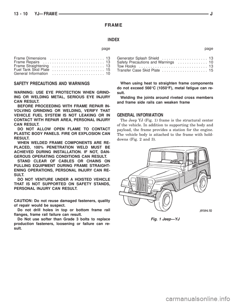
The Jeep YJ (Fig. 1) frame is the structural center
of the vehicle. In addition to supporting the body and
payload, the frame provides a station for the engine.
The vehicle body is attached to the frame with hold-
downs (Fig. 2 and 3).
Fig. 1 JeepÐYJ
13 - 10 YJÐFRAMEJ
Page 1210 of 2198
The frame is constructed of high-strength channel
steel siderails and crossmembers. The crossmembers
join the siderails and retain them in alignment in re-
lation to each other. This provides resistance to
frame twists and strains.
FRAME STRAIGHTENING
When necessary, a conventional frame that is bent
or twisted can be straightened by application of heat.
The temperature must not exceed 566ÉC (1050ÉF).
The use of a specially designed heat crayon can de-
termine the desired temperature. Excessive heat will
decrease the strength of the metal and result in a
weakened frame.
Welding the joints around riveted cross members
and frame side rails is not recommended.
A straightening repair process should be limited to
frame members that are not severely damaged.
FRAME REPAIRS
DRILLING HOLES
Do not drill holes in frame side rail top and bottom
flanges, metal fatigue can result causing frame fail-
ure. Holes drilled in the side of the frame rail must
be at least 38 mm (1.5 in.) from the top and bottom
flanges.
Additional drill holes should be located away from
existing holes.
WELDING
Use MIG, TIG or arc welding equipment to repair
welded frame components.
Frame components that have been damaged should
be inspected for cracks before returning the vehicle
to use. If cracks are found in accessible frame com-
ponents perform the following procedures.
(1) Drill a hole at each end of the crack with a 3
mm (O.125 in.) diameter drill bit.
(2) Using a suitable die grinder with 3 inch cut off
wheel, V-groove the crack to allow 100% weld pene-
tration.
(3) Weld the crack.
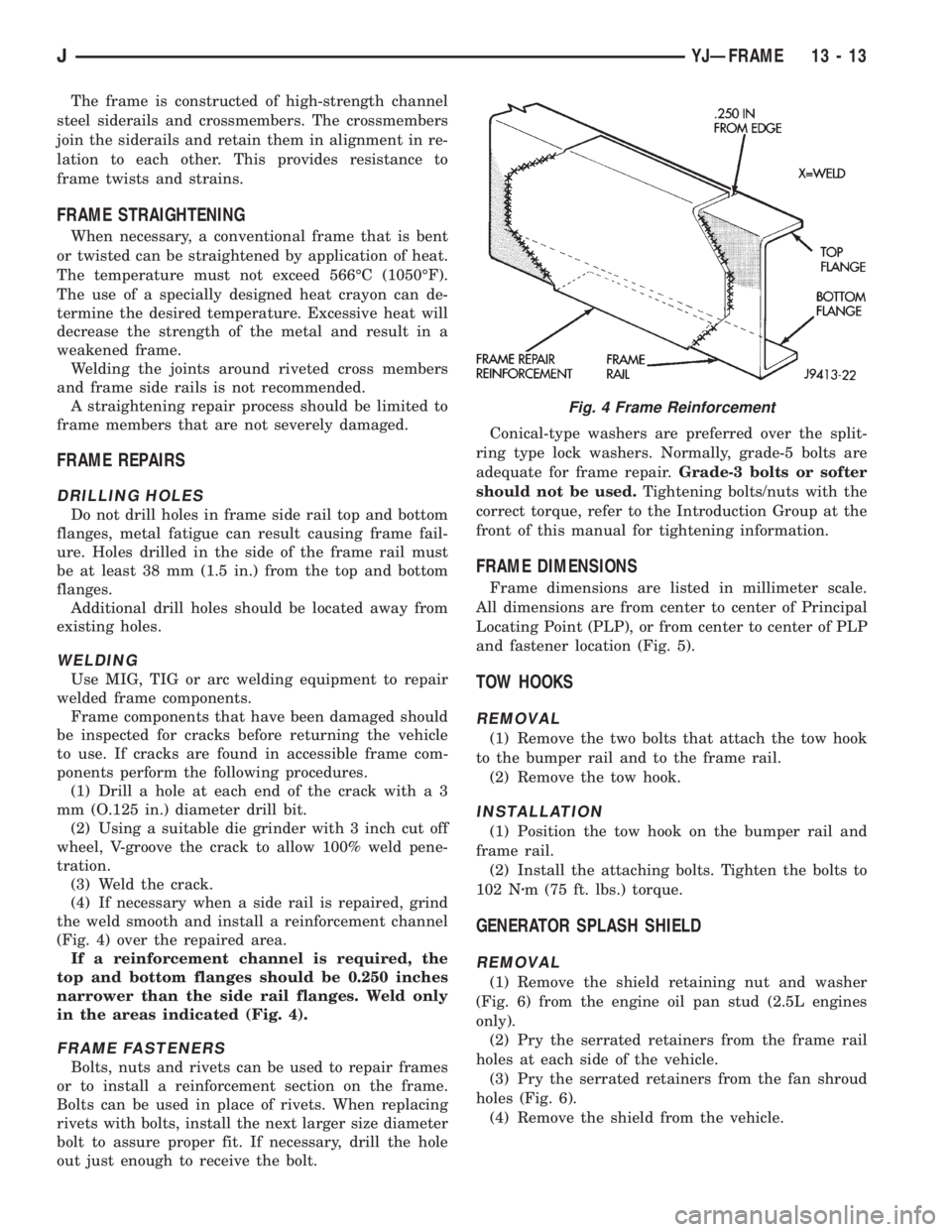
(4) If necessary when a side rail is repaired, grind
the weld smooth and install a reinforcement channel
(Fig. 4) over the repaired area.
If a reinforcement channel is required, the
top and bottom flanges should be 0.250 inches
narrower than the side rail flanges. Weld only
in the areas indicated (Fig. 4).
FRAME FASTENERS
Bolts, nuts and rivets can be used to repair frames
or to install a reinforcement section on the frame.
Bolts can be used in place of rivets. When replacing
rivets with bolts, install the next larger size diameter
bolt to assure proper fit. If necessary, drill the hole
out just enough to receive the bolt.Conical-type washers are preferred over the split-
ring type lock washers. Normally, grade-5 bolts are
adequate for frame repair.Grade-3 bolts or softer
should not be used.Tightening bolts/nuts with the
correct torque, refer to the Introduction Group at the
front of this manual for tightening information.
FRAME DIMENSIONS
Frame dimensions are listed in millimeter scale.
All dimensions are from center to center of Principal
Locating Point (PLP), or from center to center of PLP
and fastener location (Fig. 5).
TOW HOOKS
REMOVAL
(1) Remove the two bolts that attach the tow hook
to the bumper rail and to the frame rail.
(2) Remove the tow hook.
INSTALLATION
(1) Position the tow hook on the bumper rail and
frame rail.
(2) Install the attaching bolts. Tighten the bolts to
102 Nzm (75 ft. lbs.) torque.
GENERATOR SPLASH SHIELD
REMOVAL
(1) Remove the shield retaining nut and washer
(Fig. 6) from the engine oil pan stud (2.5L engines
only).
(2) Pry the serrated retainers from the frame rail
holes at each side of the vehicle.
(3) Pry the serrated retainers from the fan shroud
holes (Fig. 6).
(4) Remove the shield from the vehicle.
Fig. 4 Frame Reinforcement
JYJÐFRAME 13 - 13
Page 1211 of 2198
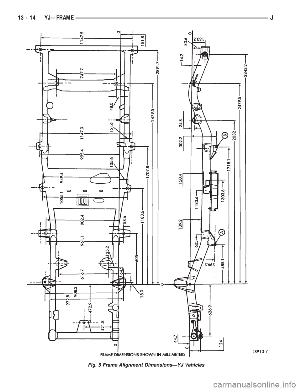
Fig. 5 Frame Alignment DimensionsÐYJ Vehicles
13 - 14 YJÐFRAMEJ
Page 1444 of 2198
30RH/32RH AUTOMATIC TRANSMISSION
GENERAL INFORMATION
INDEX
page page
Recommended Fluid....................... 67
Torque Converter......................... 67
Transmission Application.................... 67
Transmission Changes and Parts Interchangeability.. 67
Transmission Controls and Components........ 67
Transmission Identification.................. 67
TRANSMISSION APPLICATION
Chrysler 30RH and 32RH automatic transmissions
are used in XJ/YJ models. Both are 3-speed auto-
matic transmissions with a gear-type oil pump, two
clutches and bands and a planetary gear system (Fig.
1).
The 30RH is used in XJ/YJ models with a 2.5L en-
gine. The 32RH is used in YJ models with a 4.0L en-
gine.
TORQUE CONVERTER
A three element, torque converter is used for all
applications. The converter consists of an impeller,
stator, and turbine.
The converter used with 30RH/32RH transmissions
has a converter clutch. The clutch is engaged by an
electrical solenoid and mechanical module on the
valve body. The solenoid is operated by the power-
train control module.
The torque converter is a welded assembly and is
not a repairable component. The converter is serviced
as an assembly.
RECOMMENDED FLUID
The recommended and preferred fluid for 30RH/
32RH transmissions is Mopar ATF Plus, Type 7176.
Dexron II is not really recommended and should
only be used when ATF Plus is not available.
TRANSMISSION IDENTIFICATION
The transmission identification numbers are
stamped on the left side of the case just above the oil
pan gasket surface (Fig. 2). The first set of numbers
is the transmission part number. The next set of code
numbers set is the date of build. The final set of code
numbers represents the transmission serial number.
TRANSMISSION CHANGES AND PARTS
INTERCHANGEABILITY
1995 transmissions are similar to previous models
but only in appearance. Current transmissions are
dimensionally different. Do not interchange new/oldparts. Different dimensions, fluid passages, input/
output shafts, cases, bands, valve bodies and gover-
nor assemblies are just a few of the changed items.
CAUTION: Special bolts are used to attach the
driveplate to the crankshaft on models with a 2.5L
engine and 30RH transmission,. These bolts have a
smaller hex head for torque converter clearance.
DO NOT interchange these bolts with similar size
bolts for any reason.
Different governor weight assemblies are used in
30RH/32RH transmissions. The 30RH weight assem-
bly is much the same as in previous years. However,
the 32RH has a three stage governor weight assem-
bly consisting of the outer weight, a smaller weight
spring, and a new intermediate weight. Refer to the
overhaul and in-vehicle service sections for more de-
tailed information.
Plastic check balls are now used in many 30RH/
32RH valve bodies. The new check balls entered pro-
duction as a running change. Plastic and steel check
balls are not interchangeable.
A converter drainback check valve has been added
to the fluid cooler system. The one-way valve is lo-
cated in the transmission outlet (pressure) line. The
valve prevents fluid drainback when the vehicle is
parked for lengthy periods.
TRANSMISSION CONTROLS AND COMPONENTS
The transmission hydraulic control system per-
forms five basic functions, which are:
²pressure supply
²pressure regulation
²flow control
²clutch/band apply and release
²lubrication
Pressure Supply And Regulation
The oil pump generates the fluid working pressure
needed for operation and lubrication. The pump is
J30RH/32RH AUTOMATIC TRANSMISSION 21 - 67
Page 1614 of 2198
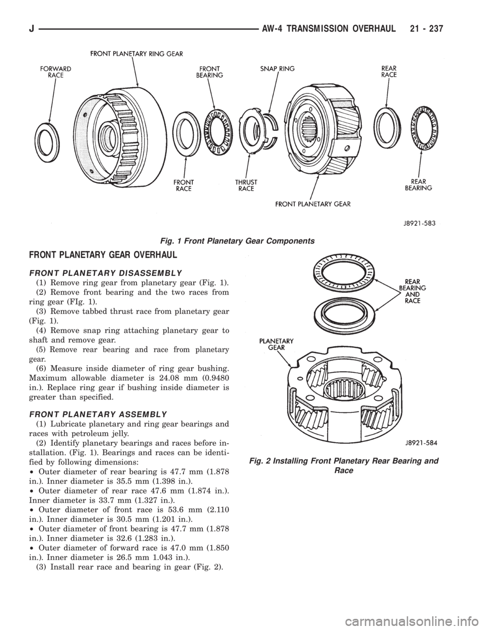
FRONT PLANETARY GEAR OVERHAUL
FRONT PLANETARY DISASSEMBLY
(1) Remove ring gear from planetary gear (Fig. 1).
(2) Remove front bearing and the two races from
ring gear (FIg. 1).
(3) Remove tabbed thrust race from planetary gear
(Fig. 1).
(4) Remove snap ring attaching planetary gear to
shaft and remove gear.
(5) Remove rear bearing and race from planetary
gear.
(6) Measure inside diameter of ring gear bushing.
Maximum allowable diameter is 24.08 mm (0.9480
in.). Replace ring gear if bushing inside diameter is
greater than specified.
FRONT PLANETARY ASSEMBLY
(1) Lubricate planetary and ring gear bearings and
races with petroleum jelly.
(2) Identify planetary bearings and races before in-
stallation. (Fig. 1). Bearings and races can be identi-
fied by following dimensions:
²Outer diameter of rear bearing is 47.7 mm (1.878
in.). Inner diameter is 35.5 mm (1.398 in.).
²Outer diameter of rear race 47.6 mm (1.874 in.).
Inner diameter is 33.7 mm (1.327 in.).
²Outer diameter of front race is 53.6 mm (2.110
in.). Inner diameter is 30.5 mm (1.201 in.).
²Outer diameter of front bearing is 47.7 mm (1.878
in.). Inner diameter is 32.6 (1.283 in.).
²Outer diameter of forward race is 47.0 mm (1.850
in.). Inner diameter is 26.5 mm 1.043 in.).
(3) Install rear race and bearing in gear (Fig. 2).
Fig. 1 Front Planetary Gear Components
Fig. 2 Installing Front Planetary Rear Bearing and
Race
JAW-4 TRANSMISSION OVERHAUL 21 - 237
Page 1623 of 2198
(12) Inspect and replace any worn or damaged
planetary gear components.
ASSEMBLING REAR PLANETARY, BRAKE
PACK, CLUTCH AND SHAFT
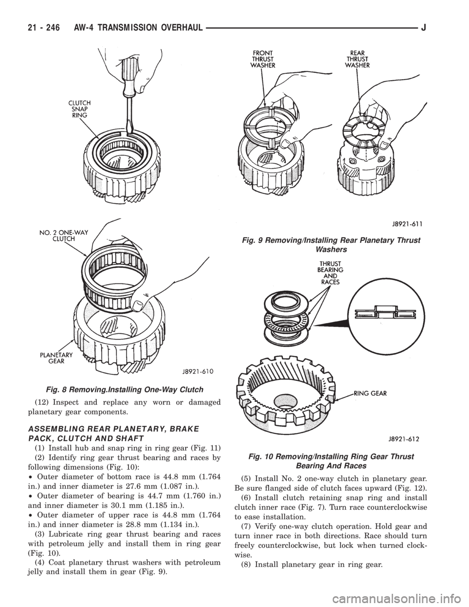
(1) Install hub and snap ring in ring gear (Fig. 11)
(2) Identify ring gear thrust bearing and races by
following dimensions (Fig. 10):
²Outer diameter of bottom race is 44.8 mm (1.764
in.) and inner diameter is 27.6 mm (1.087 in.).
²Outer diameter of bearing is 44.7 mm (1.760 in.)
and inner diameter is 30.1 mm (1.185 in.).
²Outer diameter of upper race is 44.8 mm (1.764
in.) and inner diameter is 28.8 mm (1.134 in.).
(3) Lubricate ring gear thrust bearing and races
with petroleum jelly and install them in ring gear
(Fig. 10).
(4) Coat planetary thrust washers with petroleum
jelly and install them in gear (Fig. 9).(5) Install No. 2 one-way clutch in planetary gear.
Be sure flanged side of clutch faces upward (Fig. 12).
(6) Install clutch retaining snap ring and install
clutch inner race (Fig. 7). Turn race counterclockwise
to ease installation.
(7) Verify one-way clutch operation. Hold gear and
turn inner race in both directions. Race should turn
freely counterclockwise, but lock when turned clock-
wise.
(8) Install planetary gear in ring gear.
Fig. 8 Removing.Installing One-Way Clutch
Fig. 9 Removing/Installing Rear Planetary Thrust
Washers
Fig. 10 Removing/Installing Ring Gear Thrust
Bearing And Races
21 - 246 AW-4 TRANSMISSION OVERHAULJ
Page 1632 of 2198
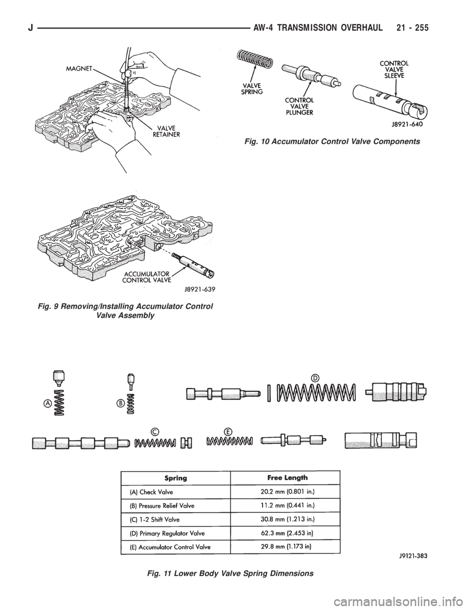
Fig. 10 Accumulator Control Valve Components
Fig. 11 Lower Body Valve Spring Dimensions
Fig. 9 Removing/Installing Accumulator Control
Valve Assembly
JAW-4 TRANSMISSION OVERHAUL 21 - 255
Page 1718 of 2198
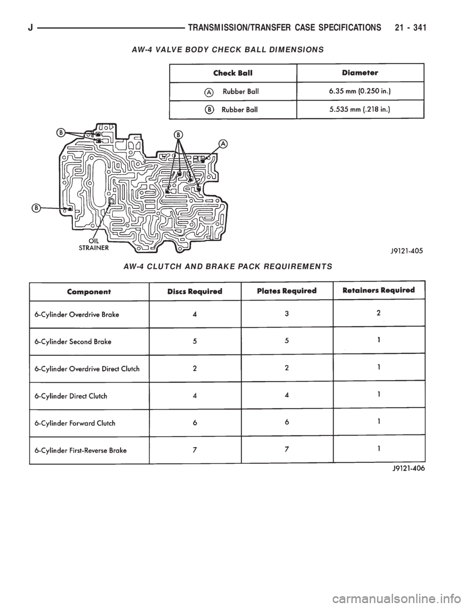
AW-4 VALVE BODY CHECK BALL DIMENSIONS
AW-4 CLUTCH AND BRAKE PACK REQUIREMENTS
JTRANSMISSION/TRANSFER CASE SPECIFICATIONS 21 - 341