1995 JEEP CHEROKEE brakes
[x] Cancel search: brakesPage 872 of 2198
ANTI-LOCK BRAKES
INDEX
page page
ABS Power Relay.......................... 1
ABS Pump Motor Relay..................... 1
ABS Warning Lamp........................ 2
Acceleration Switch......................... 1
Brake Pedal Travel Sensor................... 2
Brake Switch Input......................... 2Data Link Connector........................ 2
Diagram Index............................ 3
General Information........................ 1
Hydraulic Control Unit....................... 2
Pump Motor Speed Sensor................... 2
Wheel Speed Sensors...................... 1
GENERAL INFORMATION
Three fuses supply power for the Anti-Lock Brake
System (ABS); fuses 6 and 10 in the Power Distribu-
tion Center (PDC) and fuse 2 in the fuse block. Fuses
6 and 10 in the PDC are connected directly to battery
voltage and are HOT all times. Fuse 2 in the fuse
block is HOT when the ignition switch is the RUN
Position.
In the RUN position, the ignition switch connects
circuit A1 from fuse 6 in the PDC with circuit A38.
Circuit A38 connects to a bus bar in the fuse block.
The bus bar feeds circuit B236 through fuse 2. Fuse
2 is a 2 amp fuse.
Circuit B236 connects to the coil side of the ABS
power relay and cavity 53 of the ABS control module.
Circuit Z1 provides ground for the ABS control
module. Circuit Z1 connects to cavities 1 and 19 of
the ABS control module.
Refer to group 5, Brakes for operational descrip-
tions of ABS system components.
WHEEL SPEED SENSORS
The all wheel anti-lock system uses four wheel
speed sensors; one for each wheel. Each sensor con-
verts wheel speed into an electrical signal that it
transmits to the ABS control module. A pair of
twisted wires connect to each sensor to provide sig-
nals to the ABS control module.
Circuits B6 and B7 provide signals to ABS control
module from the right front wheel speed sensor. Cir-
cuit B6 which provides the LOW signal connects to
cavity 29 of the ABS control module. Circuit B7 con-
nects to cavity 47 of the module and provides the
HIGH signal.
Circuits B8 and B9 provide signals to ABS control
module from the left front wheel speed sensor. Cir-
cuit B8, which provides the LOW signal, connects to
cavity 30 of the ABS control module. Circuit B9 con-
nects to cavity 48 of the module and provides the
HIGH signal.
Circuits B1 and B2 provide signals to ABS control
module from the right rear wheel speed sensor. Cir-
cuit B1 which provides the LOW signal connects tocavity 45 of the ABS control module. Circuit B2 con-
nects to cavity 27 of the module and provides the
HIGH signal.
Circuits B4 and B3 provide signals to ABS control
module from the left rear wheel speed sensor. Circuit
B3, which provides the LOW signal, connects to cav-
ity 28 of the ABS control module. Circuit B4 connects
to cavity 46 of the module and provides the HIGH
signal.
ACCELERATION SWITCH
During four-wheel drive operation, the acceleration
switch provides deceleration data to the ABS control
module. Refer to Group 5, Brakes for additional in-
formation.
Circuits B515, B516, and B517 connect the acceler-
ation sensor to the ABS control module. Circuits
B515 and B516 provide switch states while circuit
B517 provides ground. At the ABS control module cir-
cuit B515 connects to cavity 25, circuit B516 connects
to cavity 43 and circuit B517 connects to cavity 26.
ABS POWER RELAY
The ABS power relay is located in the power distri-
bution center (PDC). When the ABS module grounds
the ABS power relay on circuit B207, the relay
switches to connect circuit A20 from PDC fuse 10 to
circuit B235. Circuit B236 from fuse 7 in the fuse
block splices to feed the coil side of the ABS power
relay. Circuit B207 connects to cavity 34 of the ABS
control module.
Circuit B235 is double crimped at the ABS power
relay. One branch of circuit B235 supplies power to
the coil side of the ABS pump motor relay. The other
branch of circuit B235 splices to cavities 3 and 33 of
the ABS control module and to the hydraulic control
unit.
ABS PUMP MOTOR RELAY
The ABS pump motor relay in the power distribu-
tion center (PDC) supplies voltage to the ABS pump
motor. When the ABS power relay energizes, circuit
B235 supplies battery voltage to the coil side of the
J8W-32 ANTI-LOCK BRAKESÐXJ-RHD 8W - 32 - 1
Page 873 of 2198
ABS pump motor relay. The ABS control module pro-
vides ground for the relay on circuit B116. Circuit
B116 connects to cavity 15 of the ABS control mod-
ule.
When the ABS pump motor energizes, it connects
circuit A10 from PDC fuse 8 to circuit B233. Circuit
B233 supplies battery voltage to the pump motor.
Circuit Z12 provides ground for the pump motor.
PUMP MOTOR SPEED SENSOR
The input from the pump motor speed sensor tells
the ABS control module that the pump is operating.
Circuits B219 and B220 from the control module con-
nect to the speed sensor.
BRAKE SWITCH INPUT
Circuit L50 from the stop lamp provides the brake
switch input to the ABS control module. When the
brake pedal is depressed, the stop lamp switch closes
to supply battery voltage from circuit L9 to circuit
L50. Circuit L50 connects to cavity 32 of the ABS
control module. Circuit L9 originates at fuse 4 in the
Power Distribution Center (PDC).
HYDRAULIC CONTROL UNIT
When the ABS power relay energizes, two branches
of circuit B235 splice to supply voltage to the isola-
tion and decay solenoids in the hydraulic control
unit. The hydraulic control unit contains three sepa-
rate isolation solenoids and three separate dump so-
lenoids. The ABS control module activates the decay
and isolation solenoids by providing separate ground
paths for each.
The ABS module provides a ground path for the
rear isolation solenoid on circuit B251. Circuit B251
connects to cavity 54 of the ABS control module.
For the right front isolation solenoid, the ABS mod-
ule provides a ground path on circuit B249. Circuit
B249 connects to cavity 38 of the ABS control mod-
ule.
On circuit B245, the ABS control module provides
ground for the left front isolation solenoid. Circuit
B245 connects to cavity 20 of the ABS control mod-
ule.
The ABS control module provides a ground path for
the rear dump solenoid on circuit B254. Circuit B254
connects to cavity 36 of the ABS control module.For the right front dump solenoid, the ABS module
provides a ground path on circuit B248. Circuit B248
connects to cavity 21 of the ABS control module.
On circuit B243, the ABS module provides ground
for the left dump solenoid. Circuit B243 connects to
cavity 2 of the ABS control module.
ABS WARNING LAMP
Circuit F87 provides power for the ABS warning
lamp at the instrument cluster. Ground for the ABS
warning lamp is provided by either the ABS control
module or by the ABS power relay when the relay is
not energized. The ABS control module illuminates
the lamp by providing ground on circuit B205.
Circuit B205 splices to connect to circuit B235
through a diode. When the ABS power relay is not
energized, it connects circuit B235 to circuit Z12. The
ground path for the warning lamp is through the di-
ode to circuit B235, through the ABS power relay to
ground on circuit Z12.
The diode between circuit B205 and B235 prevents
voltage from flowing to the ABS control module when
the ABS power relay switches to supply power on cir-
cuit B235.
DATA LINK CONNECTOR
Circuit D1 from cavity 23 of the ABS control mod-
ule receives data from the DRB scan tool through the
data link connector. The ABS control module trans-
mits data to the scan tool through the connector on
circuit D2. Circuit D2 originates at cavity 42 of the
ABS control module.
Through the data link connector, circuit Z12 pro-
vides ground for the DRB scan tool. Circuit Z12 ter-
minates at the right rear of the engine.
Circuit A4 from fuse 7 in the Power Distribution
Center (PDC) supplies power to fuse 13 in the PDC.
Fuse 13 powers circuit F39 which supplies battery
voltage to the scan tool through the diagnostic con-
nector.
HELPFUL INFORMATION
²Check fuses 7 and 13 in the PDC.
²If the vehicle is equipped with an automatic trans-
mission, circuits D1 and D2 are double crimped at
the data link connector and connect to the Power-
train Control Module (PCM).
8W - 32 - 2 8W-32 ANTI-LOCK BRAKESÐXJ-RHDJ
Page 874 of 2198
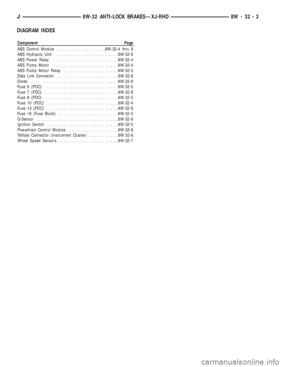
DIAGRAM INDEX
Component Page
ABS Control Module..................8W-32-4 thru 8
ABS Hydraulic Unit.......................8W-32-6
ABS Power Relay........................8W-32-4
ABS Pump Motor........................8W-32-4
ABS Pump Motor Relay....................8W-32-5
Data Link Connector......................8W-32-8
Diode................................8W-32-6
Fuse 6 (PDC)...........................8W-32-5
Fuse 7 (PDC)...........................8W-32-8
Fuse 8 (PDC)...........................8W-32-5
Fuse 10 (PDC)..........................8W-32-4
Fuse 13 (PDC)..........................8W-32-8
Fuse 18 (Fuse Block)......................8W-32-5
G-Sensor..............................8W-32-8
Ignition Switch..........................8W-32-5
Powertrain Control Module..................8W-32-8
Telltale Connector (Instrument Cluster)...........8W-32-6
Wheel Speed Sensors......................8W-32-7
J8W-32 ANTI-LOCK BRAKESÐXJ-RHD 8W - 32 - 3
Page 1237 of 2198
energized). This is done to compensate for the re-
duced flow through injector caused by the lowered
voltage.
BRAKE SWITCHÐPCM INPUT
When the brake light switch is activated, the pow-
ertrain control module (PCM) receives an input indi-
cating that the brakes are being applied. After
receiving this input, the PCM maintains idle speed to
a scheduled rpm through control of the idle air con-
trol (IAC) motor. The brake switch input is also used
to operate the speed control system.
CAMSHAFT POSITION SENSORÐPCM INPUT
A sync signal is provided by the camshaft position
sensor located in the distributor (Fig. 5). The sync
signal from this sensor works in conjunction with the
crankshaft position sensor to provide the powertrain
control module (PCM) with inputs. This is done to es-
tablish and maintain correct injector firing order.
Refer to Camshaft Position Sensor in Group 8D, Ig-
nition System for more information.
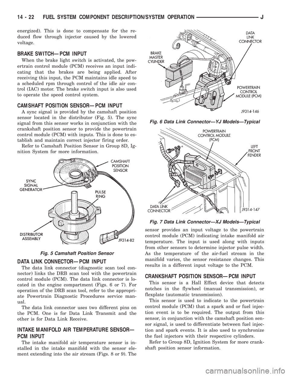
DATA LINK CONNECTORÐPCM INPUT
The data link connector (diagnostic scan tool con-
nector) links the DRB scan tool with the powertrain
control module (PCM). The data link connector is lo-
cated in the engine compartment (Figs. 6 or 7). For
operation of the DRB scan tool, refer to the appropri-
ate Powertrain Diagnostic Procedures service man-
ual.
The data link connector uses two different pins on
the PCM. One is for Data Link Transmit and the
other is for Data Link Receive.
INTAKE MANIFOLD AIR TEMPERATURE SENSORÐ
PCM INPUT
The intake manifold air temperature sensor is in-
stalled in the intake manifold with the sensor ele-
ment extending into the air stream (Figs. 8 or 9). Thesensor provides an input voltage to the powertrain
control module (PCM) indicating intake manifold air
temperature. The input is used along with inputs
from other sensors to determine injector pulse width.
As the temperature of the air-fuel stream in the
manifold varies, the sensor resistance changes. This
results in a different input voltage to the PCM.
CRANKSHAFT POSITION SENSORÐPCM INPUT
This sensor is a Hall Effect device that detects
notches in the flywheel (manual transmission), or
flexplate (automatic transmission).
This sensor is used to indicate to the powertrain
control module (PCM) that a spark and or fuel injec-
tion event is to be required. The output from this
sensor, in conjunction with the camshaft position sen-
sor signal, is used to differentiate between fuel injec-
tion and spark events. It is also used to synchronize
the fuel injectors with their respective cylinders.
Refer to Group 8D, Ignition System for more crank-
shaft position sensor information.
Fig. 5 Camshaft Position Sensor
Fig. 6 Data Link ConnectorÐYJ ModelsÐTypical
Fig. 7 Data Link ConnectorÐXJ ModelsÐTypical
14 - 22 FUEL SYSTEM COMPONENT DESCRIPTION/SYSTEM OPERATIONJ
Page 1274 of 2198
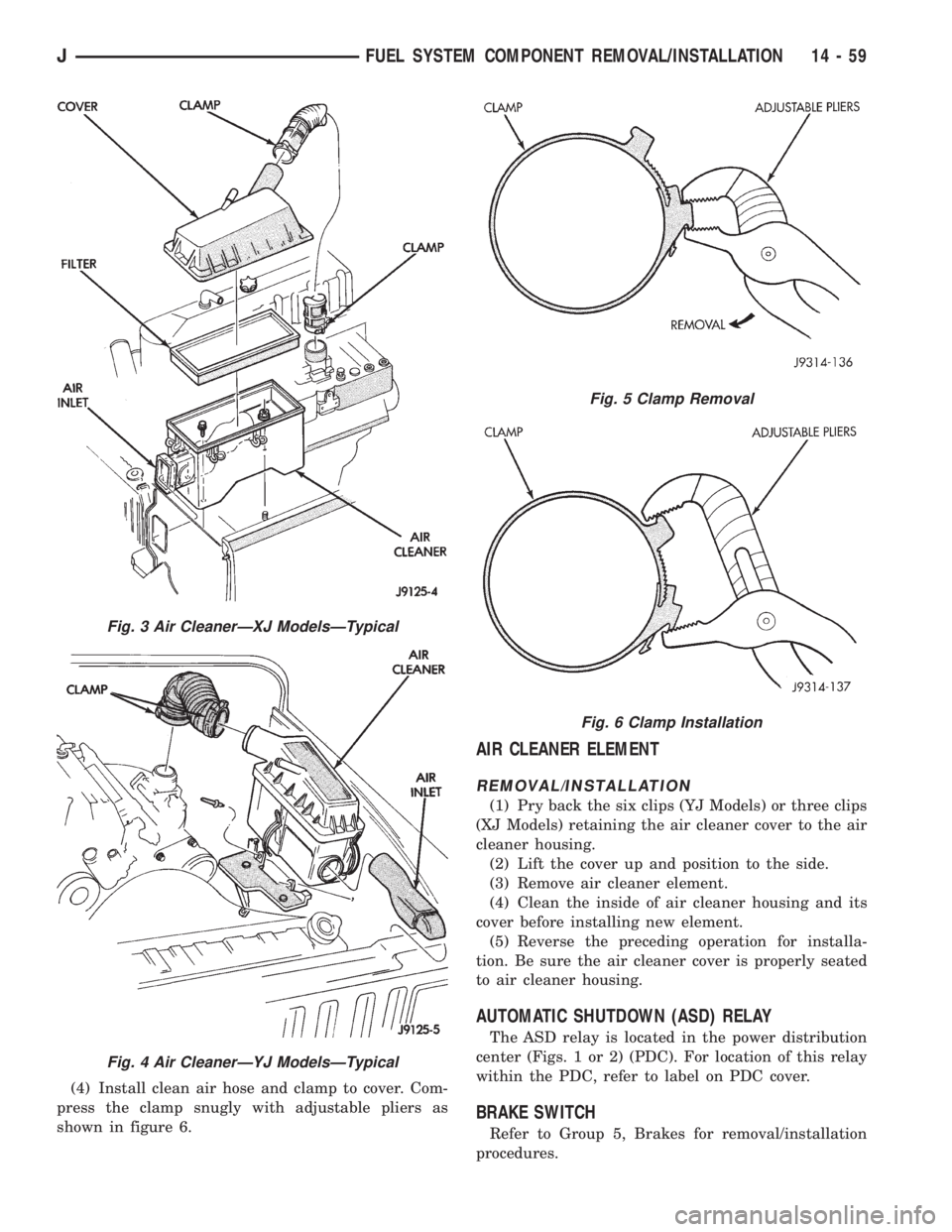
(4) Install clean air hose and clamp to cover. Com-
press the clamp snugly with adjustable pliers as
shown in figure 6.
AIR CLEANER ELEMENT
REMOVAL/INSTALLATION
(1) Pry back the six clips (YJ Models) or three clips
(XJ Models) retaining the air cleaner cover to the air
cleaner housing.
(2) Lift the cover up and position to the side.
(3) Remove air cleaner element.
(4) Clean the inside of air cleaner housing and its
cover before installing new element.
(5) Reverse the preceding operation for installa-
tion. Be sure the air cleaner cover is properly seated
to air cleaner housing.
AUTOMATIC SHUTDOWN (ASD) RELAY
The ASD relay is located in the power distribution
center (Figs. 1 or 2) (PDC). For location of this relay
within the PDC, refer to label on PDC cover.
BRAKE SWITCH
Refer to Group 5, Brakes for removal/installation
procedures.
Fig. 3 Air CleanerÐXJ ModelsÐTypical
Fig. 4 Air CleanerÐYJ ModelsÐTypical
Fig. 5 Clamp Removal
Fig. 6 Clamp Installation
JFUEL SYSTEM COMPONENT REMOVAL/INSTALLATION 14 - 59
Page 1286 of 2198
SERVICE DIAGNOSIS
INDEX
page page
Runout.................................. 4
Unbalance............................... 3Universal Joint Angle Measurement............. 4
Vibration................................. 3
VIBRATION
Tires that are out-of-round or wheels that are un-
balanced will cause a low frequency vibration. Refer
to Group 22, Wheels and Tires for additional infor-
mation.
Brake drums that are unbalanced will cause a
harsh, low frequency vibration. Refer to Group 5,
Brakes for additional information.
Driveline vibration can also result from loose or
damaged engine mounts. Refer to Group 21, Trans-
missions for additional information.
Propeller shaft vibration will increase as the vehi-
cle speed is increased. A vibration that occurs within
a specific speed range is not caused by propeller
shaft unbalance. Defective universal joints or an in-
correct propeller shaft angle are usually the cause.
UNBALANCE
If propeller shaft unbalance is suspected, it can be
verified with the following procedure.
Removing and re-indexing the propeller shaft
180É may eliminate some vibrations.
²Clean all the foreign material from the propeller
shaft and the universal joints.²Inspect the propeller shaft for missing balance
weights, broken welds, and bent areas.If the pro-
peller shaft is bent, it must be replaced.
²Ensure the universal joints are not worn, are prop-
erly installed, and are correctly aligned with the
shaft.
²Check the universal joint clamp screws torque
(1) Raise the vehicle.
(2) Remove the wheel and tires assembly. Install
the wheel lug nuts to retain the brake drums.
(3) Mark and number the shaft six inches from the
yoke end at four positions 90É apart.
(4) Run and accelerate the vehicle until vibration
occurs. Note the intensity and speed the vibration oc-
curred. Stop the engine.
(5) Install a screw clamp at position 1 (Fig. 1).
(6) Start the engine and re-check for vibration. If
there is little or no change in vibration, move the
clamp to one of the other three positions. Repeat the
vibration test.
(7) If there is no difference in vibration at the
other positions, the vibration may not be propshaft
unbalance.
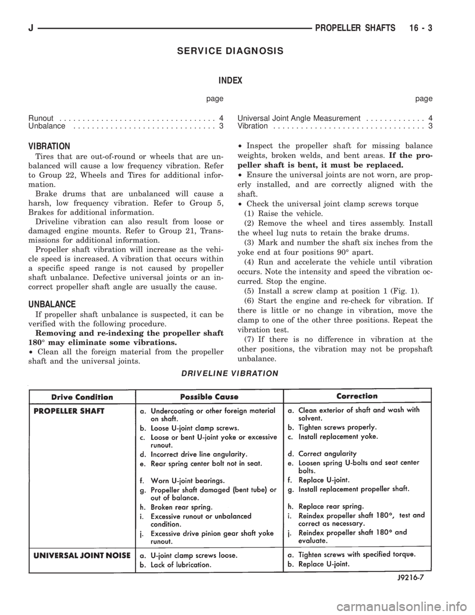
DRIVELINE VIBRATION
JPROPELLER SHAFTS 16 - 3
Page 1448 of 2198
(4) Apply parking brakes.
(5) Shift transmission momentarily into all gear
ranges. Then shift transmission back to Neutral.
(6) Clean top of filler tube and dipstick to keep dirt
from entering tube.
(7) Remove dipstick and check fluid level as fol-
lows:
(a) Dipstick has three fluid level indicator levels
(Fig. 1) which are: a MIN dot, an OK crosshatch
area, and a MAX fill arrow.
(b) Correct maximum level is to MAX arrow
mark. Correct acceptable level is to OK mark in
crosshatch area.
(c) Incorrect level is at or below MIN dot.
(d) If fluid is low, add only enough Mopar ATF
Plus to restore correct level. Do not overfill.
CAUTION: Do not overfill the transmission. Overfill-
ing may cause leakage out the pump vent which
can be mistaken for a pump seal leak. Overfilling
will also cause fluid aeration and foaming as the ex-
cess fluid is picked up and churned by the gear
train. This will significantly reduce fluid life.
EFFECTS OF INCORRECT FLUID LEVEL
A low fluid level allows the pump to take in air
along with the fluid. Air in the fluid will cause fluid
pressures to be low and develop slower than normal.
If the transmission is overfilled, the gears churn
the fluid into foam. This aerates the fluid causing the
same conditions that occur with a low level.
In either case, air bubbles cause fluid overheating,
oxidation and varnish buildup which interferes with
valve, clutch and servo operation. Foaming also
causes fluid expansion which can result in fluid over-
flow from the transmission vent or fill tube. Fluid
overflow can easily be mistaken for a leak if inspec-
tion is not careful.
TRANSMISSION THROTTLE VALVE CABLE
ADJUSTMENT
Throttle cable adjustment is important to proper
operation. This adjustment positions the throttle
valve which controls shift speed, quality and part
throttle downshift sensitivity.
If cable adjustment setting is too short, early shifts
and slippage between shifts may occur. If the setting
is too long, shifts may be delayed and part throttle
downshifts may be very sensitive. Refer to the In-Ve-
hicle Service section for adjustment procedure.
GEARSHIFT CABLE/LINKAGE ADJUSTMENT
Gearshift cable/linkage adjustment is important be-
cause it positions the valve body manual valve. Incor-
rect adjustment will cause creeping in Neutral,
premature clutch wear, delayed engagement in any
gear, or a no-start in Park or Neutral position.Proper operation of the neutral start switch will
provide a quick check on adjustment. Refer to the In-
Vehicle Service section for adjustment procedure.
ROAD TEST
Before road testing, be sure the fluid level and all
cable/linkage adjustments have been checked and ad-
justed if necessary.
Observe engine performance during the road test. A
poorly tuned engine will not allow an accurate anal-
ysis of transmission operation.
Operate the transmission in all gear ranges. Check
for slippage and shift variations. Note whether the
shifts are harsh, spongy, delayed, early, or if part
throttle downshifts are sensitive.
Watch closely for slippage or engine flare which
usually indicates clutch, band or overrunning clutch
problems. If the condition is advanced, an overhaul
may be necessary to restore normal operation.
A slipping clutch or band can often be determined
by comparing which internal units are applied in the
various gear ranges. The Clutch and Band Applica-
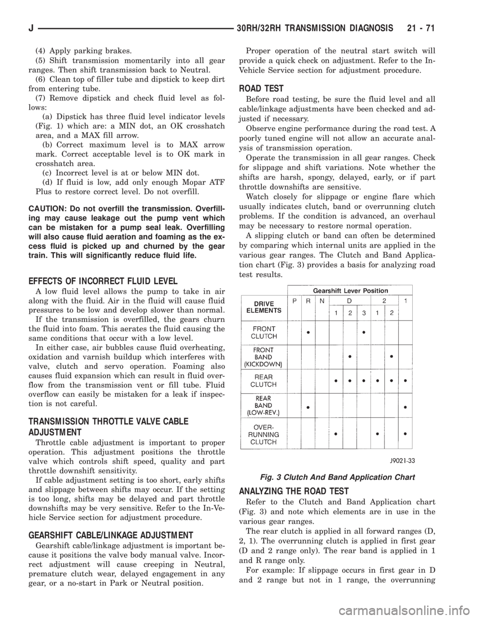
tion chart (Fig. 3) provides a basis for analyzing road
test results.
ANALYZING THE ROAD TEST
Refer to the Clutch and Band Application chart
(Fig. 3) and note which elements are in use in the
various gear ranges.
The rear clutch is applied in all forward ranges (D,
2, 1). The overrunning clutch is applied in first gear
(D and 2 range only). The rear band is applied in 1
and R range only.
For example: If slippage occurs in first gear in D
and 2 range but not in 1 range, the overrunning
Fig. 3 Clutch And Band Application Chart
J30RH/32RH TRANSMISSION DIAGNOSIS 21 - 71
Page 1450 of 2198
Test Two-Transmission In 2 Range
This test checks pump output and pressure
regulation. Use 100 psi Test Gauge C-3292 for
this test.
(1) Connect test gauge to line pressure port (Fig.
4).
(2) Start and run engine at 1000 rpm.
(3) Move valve body selector lever one detent rear-
ward from full forward position (this is 2 range).
(4) Move transmission throttle lever from full for-
ward to full rearward position and read pressure at
both gauges.
(5) Line pressure should be 54-60 psi (372-414
kPa) with throttle lever forward and gradually in-
crease to 90-96 psi (620-662 kPa) as lever is moved
rearward.
Test Three-Transmission In Third Gear
This test checks pressure regulation and con-
dition of the front and rear clutch circuits.
Both gauges are required for this test.
(1) Connect one test gauge to line pressure port
and other gauge to front servo pressure port (Fig. 4).
Either gauge can be used at either port.
(2) Start and run engine at 1600 rpm.
(3) Move selector lever two detents rearward from
full forward position. This is D range.
(4) Read pressures on both gauges as transmission
throttle lever is moved from full forward to full rear-
ward position.
(a) Line pressure in third gear, should be 54-60
psi (372-414 kPa) with throttle lever forward and
gradually increase as lever is moved rearward.
(b) Front servo pressure in third gear, should be
within 3 psi (21 kPa) of line pressure, up to down-
shift point.
Test Four-Transmission In Reverse
This test checks pump output, pressure regu-
lation and the front clutch and rear servo cir-
cuits. Use 300 psi Pressure Test Gauge C-3293
for this test.
(1) Connect pressure test gauge to rear servo port
(Fig. 5).
(2) Start and run engine at 1600 rpm for test.
(3) Move valve body selector lever four detents
rearward from full forward position. This is Reverse
range.
(4) Move throttle lever all way forward then all the
way rearward and note gauge readings.
(5) Pressure should be 145 - 175 psi (1000-1207
kPa) with lever forward and increase to 230 - 280 psi
(1586-1931 kPa) as lever is moved rearward.
Test Five-Governor Pressure
This test checks governor operation by mea-
suring governor pressure response to changesin engine speed. It is usually not necessary to
check governor operation unless shift speeds
are incorrect or if the transmission will not
shift up or down. Use 100 psi Pressure Test
Gauge C-3292 for this test.
(1) Connect test gauge to governor pressure port
(Figs. 5 and 6).
(2) Move selector lever to D range.
(3) Apply service brakes. Start and run engine at
curb idle speed and note pressure. At idle and with
wheels stopped, pressure should be zero to 1-1/2 psi
maximum. If pressure exceeds this figure, governor
valve or weights are sticking open.
(4) Slowly increase engine speed and observe
speedometer and pressure test gauge. Governor pres-
sure should increase in proportion to vehicle speed
(approximately 1 psi for every 1 mph shown on
speedometer).
(5) Governor pressure rise should be smooth and
drop back to 0 to 1-1/2 psi when throttle is closed
and wheels are stopped.
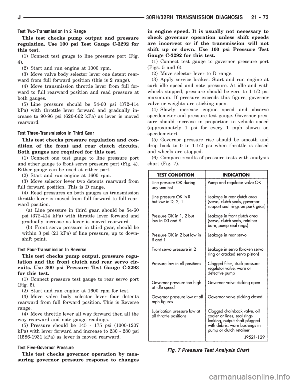
(6) Compare results of pressure tests with analysis
chart (Fig. 7).
Fig. 7 Pressure Test Analysis Chart
J30RH/32RH TRANSMISSION DIAGNOSIS 21 - 73