Page 302 of 1708

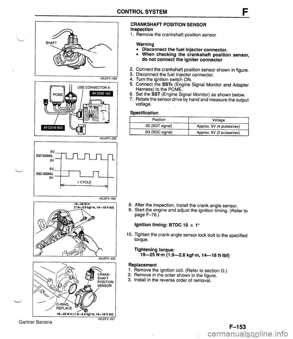
CONTROL SYSTEM 1 1 USE CONNECTOR A CRANKSHAFT POSITION SENSOR Inspection 1. Remove the crankshaft position sensor 5v- - - - SGGSIGNAL ov Warning Disconnect the fuel injector connector. When checking the crankshaft position sensor, do not connect the igniter connector - - - - I 1 CYCLE < > 2. Connect the crankshaft position sensor shown in figure. 3. Disconnect the fuel injector connector. 4. Turn the ignition switch ON. 5. Connect the SSTs (Engine Signal Monitor and Adapter Harness) to the PCME. 6. Set the SST (Engine Signal Monitor) as shown below. 7. Rotate the sensor drive by hand and measure the output voltage. Specification I 1 - Position - ~oltaael 8. After the inspection, install the crank angle sensor. 9. Start the engine and adjust the ignition timing. (Refer to page F-76.) 2E (SGT signal) 2G (SGC signal) Ignition timing: BTDC 10 2 1" Approx. 5V (4 pulseslrev) Approx. 5V (2 pulseslrev) 10. Tighten the crank angle sensor lock bolt to the specified torque. Tightening torque: 19-25 N-m (1 .+2.6 kgfem, 14-1 8 ftelbf} Replacement 1. Remove the ignition coil. (Refer to section G.) 2. Remove in the order shown in the figure. 3. Install in the reverse order of removal. Gartner Banana
Page 303 of 1708

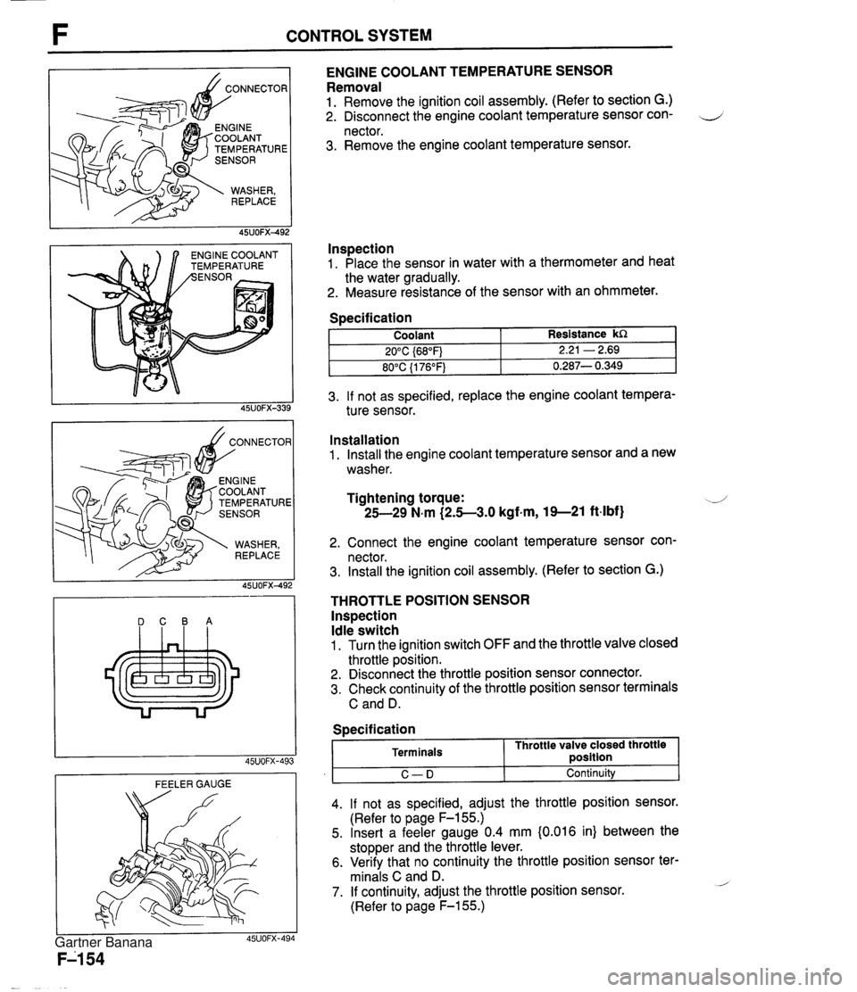
CONTROL SYSTEM TEMPERATURE NGlNE COOLANT EMPERATURE ENGINE COOLANT TEMPERATURE SENSOR Removal 1. Remove the ignition coil assembly. (Refer to section G.) 2. Disconnect the engine coolant temperature sensor con- 4 nector. 3. Remove the engine coolant temperature sensor. lnspection 1. Place the sensor in water with a thermometer and heat the water gradually. 2. Measure resistance of the sensor with an ohmmeter. 3. If not as specified, replace the engine coolant tempera- ture sensor. Specification DCBA Coolant 20°C {68"F) 80°C {I 76°F) FEELER GAUGE Resistance kR 2.21 - 2.69 0.287- 0.349 Installation 1. Install the engine coolant temperature sensor and a new washer. Tightening torque: -J 25-29 N.m (2.5-3.0 kgf-m, 19--21 ft-lbf) 2. Connect the engine coolant temperature sensor con- nector. 3. Install the ignition coil assembly. (Refer to section G.) THROTTLE POSITION SENSOR lnspection Idle switch 1. Turn the ignition switch OFF and the throttle valve closed throttle position. 2. Disconnect the throttle position sensor connector. 3. Check continuity of the throttle position sensor terminals C and D. I C-D I Continuity 4. If not as specified, adjust the throttle position sensor. (Refer to page F-155.) 5. Insert a feeler gauge 0.4 mm {0.016 in) between the stopper and the throttle lever. 6. Verify that no continuity the throttle position sensor ter- minals C and D. - 7. If continuity, adjust the throttle position sensor. (Refer to page F-155.) Specification Terminals Throttle valve closed throttle ~osition Gartner Banana
Page 306 of 1708

CONTROL SYSTEM LOCK 4. If not as specified, replace the main relay. MAIN RELAY lnspection 1. Verify that the main relay clicks when turning the ignition switch OFF -+ ON. 2. Apply battery positive voltage to terminal A and ground terminal B of the main relay. 3. Use an ohmmeter to check continuity of the terminals as shown. CLUTCH SWITCH Inspection 1. Disconnect the clutch switch connector. 2. Connect an ohmmeter to the switch. 3. Check continuity of the switch. Battery positive voltage applied - Continuity - Terminals CD L 4. If not as specified, replace the clutch switch. Battery positive voltage not applied No continuity Pedal Depressed Released Replacement 1. Disconnect the clutch switch connector. 2. Loosen the locknut. 3. Remove the clutch switch. 4. Install in the reverse order of removal. 5. Adjust the pedal height. (Refer to Section H.) Continuity Yes No 4. If not as specified, replace the neutral switch. NEUTRAL SWITCH lnspection 1. Disconnect the neutral switch connector. 2. Connect an ohmmeter to the switch. 3. Check continuity of the switch. Transmission Neutral Other ranges Continuity , Yes No Gartner Banana
Page 308 of 1708

Before beginning any service procedure. refer to section T of this manual for air bag system service warnings and audio antitheft system alarm conditions . ENGINE ELECTRICAL SYSTEM INDEX ....................................... G- 2 OUTLINE ..................................... G- 3 SPECIFICATIONS ........................... G- 3 TROUBLESHOOTING GUIDE .................. G- 4 CHARGING SYSTEM .......................... G- 6 PREPARATION ............................. G- 6 CIRCUIT DIAGRAM ......................... G- 6 TROUBLESHOOTING ....................... G- 7 BATTERY .................................. G- 8 ALTERNATOR .............................. G-10 DRIVE BELT ................................ G-13 IGNITION SYSTEM ............................ G-15 PREPARATION ............................. G-15 CIRCUIT DIAGRAM ......................... G-15 TROUBLESHOOTING ....................... G-16 IGNITION TIMING ........................... G-17 SPARK PLUG ............................... G-18 IGNITION COIL ............................. G-19 IGNITER ................................... G-19 HIGH-TENSION LEAD ....................... G-20 STARTING SYSTEM ........................... G-21 CIRCUIT DIAGRAM ......................... G-21 TROUBLESHOOTING ....................... G-21 STARTER .................................. G-22 STARTER INTERLOCK SWITCH (MT) ......... G-28 45UOGX401 Gartner Banana
Page 311 of 1708
TROUBLESHOOTING GUIDE TROUBLESHOOTING GUIDE Problem Will not crank Cranks slowly Discharged battery Misfire G-5 Will not crank I Will not crank I Check 1 1 , YES, Check if engine cranks with fully charged battery Check charging system (Refer to page G-7) I NO Check ignition switch (Refer to section T), starter interlock switch (Refer to page G-28) and parWneutral switch (Refer to section K) 45uOOx-OC - Check 1 Check if click is heard from starter magnetic switch when ignition is turned to START Cranks slowly Check starting system (Refer to page G-21) Crank slowly Check 1 Check charging system (Refer to page G-7) I NO ---- Check starting system (Refer to page G-21) Check 1 Gartner Banana
Page 315 of 1708
CHARGING SYSTEM 1. Disconnect the battery cables from the battery. 2. Connect a voltmeter to the battery. BATTERY Warning Hydrogen gas is produced during normal battery d operation. A battery-related explosion can cause serious injury. Keep all flames (including ciga- rettes), heat, and sparks away from the top and surrounding area of open battery cells. Caution To prevent damage to electrical components or the battery, turn all accessories off and stop the engine before performing maintenance or re- charging the battery. Caution Obtain the code number and deactivate the audio anti-theft system before disconnecting the bat- tery. (Refer to section T.) Inspection Caution When disconnecting the battery, remove the neg- ative cable first and install it last to prevent dam- age to electrical components or the battery. Gartner Banana
Page 317 of 1708

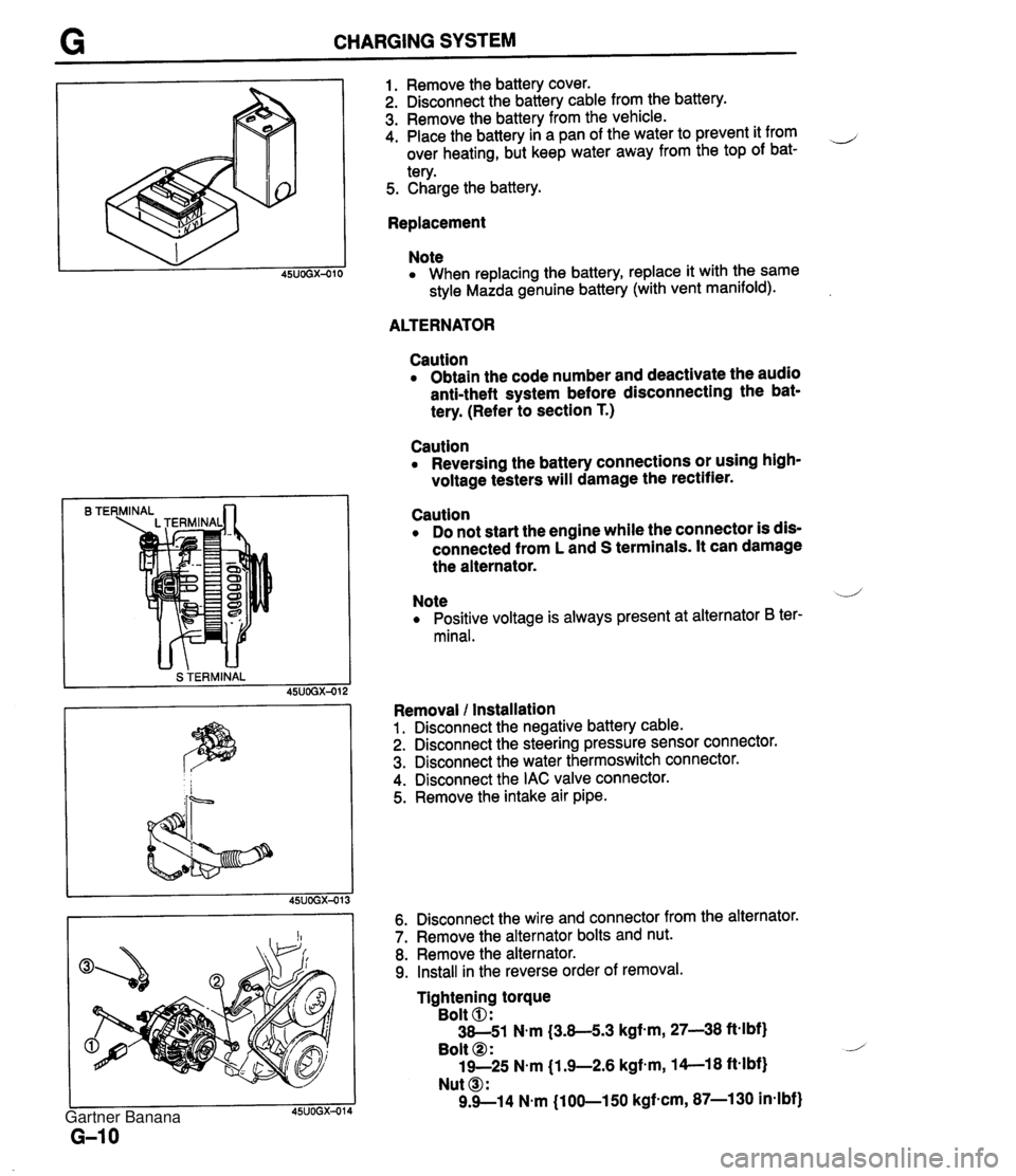
CHARGING SYSTEM B TE S TERMINAL 1. Remove the battery cover. 2. Disconnect the battery cable from the battery. 3. Remove the battery from the vehicle. 4. Place the battery in a pan of the water to prevent it from ,-, over heating, but keep water away from the top of bat- tery. 5. Charge the battery. Replacement Note When replacing the battery, replace it with the same style Mazda genuine battery (with vent manifold). ALTERNATOR Caution Obtain the code number and deactivate the audio anti-theft system before disconnecting the bat- tery. (Refer to section T.) Caution Reversing the battery connections or using high- voltage testers will damage the rectifier. Caution Do not start the engine while the connector is dis- connected from L and S terminals. It can damage the alternator. Note .--,' Positive voltage is always present at alternator B ter- minal. Removal l Installation 1. Disconnect the negative battery cable. 2. Disconnect the steering pressure sensor connector. 3. Disconnect the water thermoswitch connector. 4. Disconnect the IAC valve connector. 5. Remove the intake air pipe. 6. Disconnect the wire and connector from the alternator. 7. Remove the alternator bolts and nut. 8. Remove the alternator. 9. Install in the reverse order of removal. Tightening torque Bolt 0: 38-51 N.m (3.8-5.3 kgf-m, 27-38 ftelbf) Bolt @ : 19-25 N.m j1.9-2.6 kgfem, 14--18 ft-lbf) Nut @I: 9.9--14 N.m (100-150 kgf-cm, 87-1 30 in-lbf) Gartner Banana
Page 323 of 1708
IGNITION SYSTEM TROUBLESHOOTING Misfire I 1 Check 1 NO NO 1. Turn ignition switch ON 2. Connect data link connector terminals (TEN) and (GND) with a jumper wire 3. Check if MIL illuminates I Check if resistance of secondary windings is OK Replace ignition coil (Refer to page G-19) (Refer to page G-19) I Refer to section F Check 2 Check if resistance of Replace high-tension lead (Refer to page G-20) (Refer to page G-20) I I Check 3 Check if spark plug is OK ( I Check 4 1 YES I Check PCME terminals (Refer to section F) a 1 G, 1 H (Igniter) 0 2E, 2G (Crankshaft position sensor) Repair or replace (Refer to section F) ( 2F, 20 ass airflow sensor) YES Replace ignition coil (igniter malfunction) 1 Check 1 Check 3 Check 2 PLUG WEAR AND CARBON BUILDUP BURNS DAMAGE AND DETERIORATION DAMAGE Gartner Banana