Page 881 of 1708

T WARNING LIGHT AND SENDER UNIT TROUBLESHOOTING Check the METER 15A fuse in the fuse box before troubleshooting. If it is burnt, replace it after checking and repairing the wiring harness. i/ Brake System Warning Light I Symptom: Brake system warning light remains illuminated. 45UOTX-063 Step 1 - Check brake fluid level Check brake fluid level. Below MIN I I Check brake system (Refer to section P) I Brake fluid level Action Step 2 - Check parking brake switch 1. Disconnect the parking brake switch connector. 2. Check for continuity between the terminal of the switch and ground. Above MIN Go to Step 2 3. If not as specified, adjust or replace the parking brake switch. (Refer to section P.) 4. If the switch is OK, go to Step 3. I Step 3 - Check brake fluid level sensor I 1. Check for continuity of the sensor. *. 1' Lever Pulled one notch Released Continuity Yes No - I Above MIN No Brake fluid level Below MIN 2. If not as specified, replace the level sensor. 3. If the sensor is OK, repair the wiring harness. Continuity Yes Gartner Banana
Page 882 of 1708

WARNING LIGHT AND SENDER UNIT T Symptom: Brake system warning light does not illuminate when parking brake is on. (Ignition switch to ON) 45UOTX-065 Remedy 1. Disconnect the parking brake switch connector. 2. Check for continuity between the terminal of the switch and ground. I Released 1 No I Lever 3. If not as specified, adjust or replace the parking brake switch. 4. If the switch is OK, repair the wiring harness. Continuity 010 OFF Indicator Light Symptom: O/D off indicator light does not illuminate when O/D off switch turned on. 45UOTX-069 Pulled one notch I Yes Symptom: Brake system warning light does not illuminate when brake fluid in reservoir tank is below MIN. 45UOTX-067 Remedy 1. Check the bulb of the O/D off indicator light. 2. If the bulb is burned out, replace it. u Remedy 1. Disconnect the brake fluid level sensor connector. 2. Check for continuity of the brake fluid level sensor. Brake fluid level Below MIN Above MIN Continuity Yes No 3. If not as specified, replace the level sensor. 4. If the sensor is OK, repair the wiring harness. Gartner Banana
Page 884 of 1708

WARNING LIGHT AND SENDER UNIT T OHMMETER Washer Level Indicator lnspection 1. Disconnect the connector from the washer level sensor. 2. Jump terminal-wire L (harness side) to a body ground. 3. Start the engine and check that the WASHER indicator illuminates. 4. If there is no illumination, check the bulb, wiring harness, and sensor. Replace or repair as necessary. Washer Level Sensor lnspection 1. Connect the sensor connector (sensor side) to an ohm- meter. 2. Move the sensor float up and down. 3. Verify that there is continuity when the float is at the low- est point. BRAKE FLUID LEVEL SENSOR lnspection 1. Check for continuity of the sensor. 2. If continuity is not as specified, replace the level sensor. Float level Below MIN Above MIN BUCKLE SWITCt Continuity Yes No OHMMETER -1 PARKING BRAKE SWITCH lnspection 1. Disconnect the parking brake switch connector. 2. Check for continuity between the switch connector and ground. I Lever I Continuity I 3. If continuity is not as specified, adjust or replace the parking brake switch. (Refer to section P.) Pulled one notch Released BUCKLE SWITCH lnspection 1. Disconnect the buckle switch connector 2. Check for continuity of the switch. Yes No Seat belt I Continuity Seat belt buckled Seat belt unbuckled No Yes 3. If continuity is not as specified, replace the buckle switch. Gartner Banana
Page 1117 of 1708

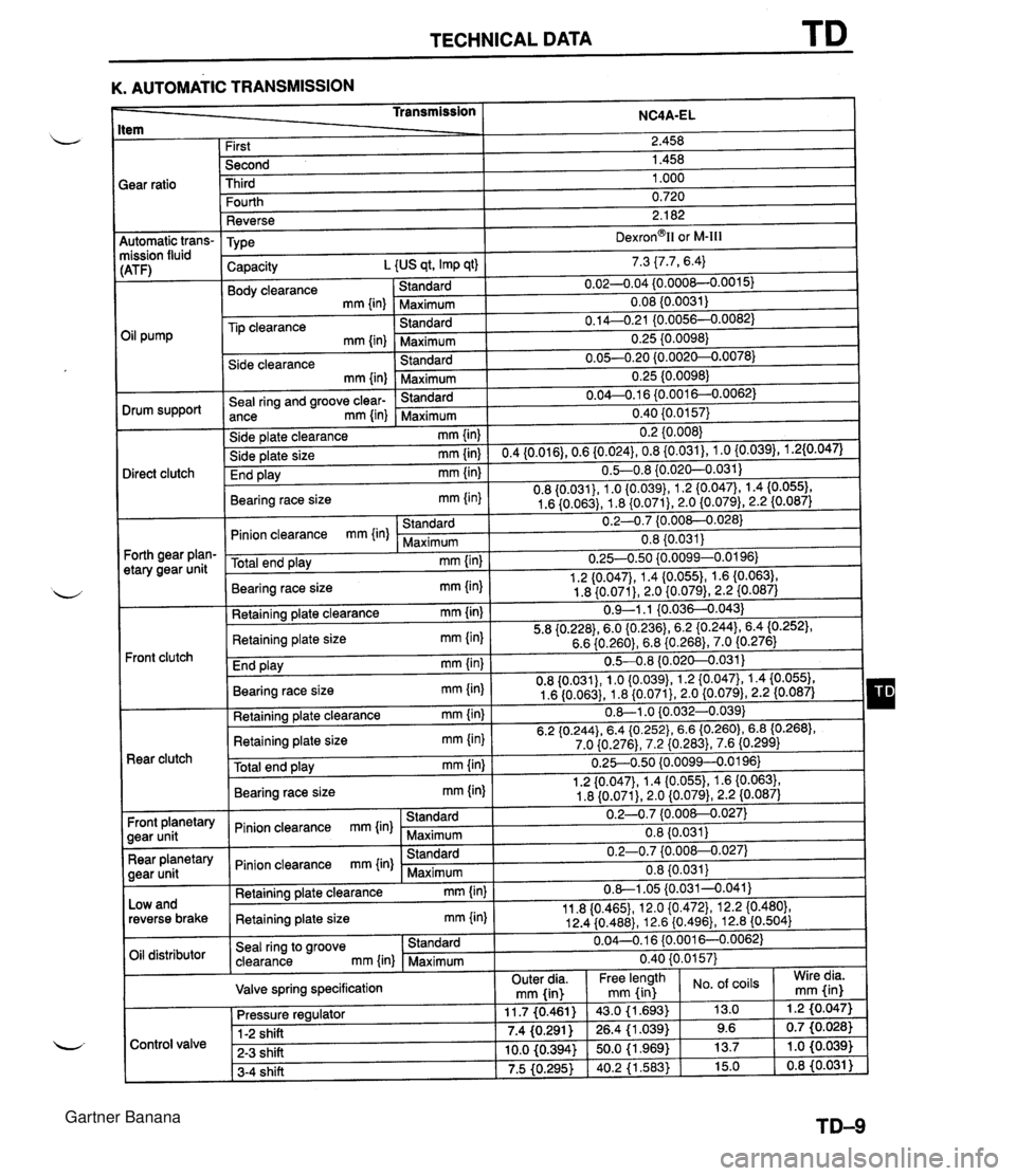
TECHNICAL DATA K. AUTOMATIC TRANSMISSION tem Transmission ;ear ratio NC4A-EL 4utomatic trans- nission fluid :ATF) 3il pump Drum support Direct clutch Forth gear plan- etary gear unit Front clutch Rear clutch Front planetary gear unit Rear planetary gear unit Low and reverse brake Oil distributor First Second Third Fourth Reverse TY pe Capacity L {US qt, Imp qt) Body clearance Standard mm {in) -Maximum Tip clearance Standard mm {in) Maximum Side clearance Standard mm {in) Maximum Seal ring and groove clear- Standard ance mm {in) Maximum Side plate clearance mm {in) Side plate size mm{in) End play mm {in) Bearing race size mm {in) Standard Pinion clearance mm {in) Maximum Total end play mm {in) Bearing race size mm (in) Retaining plate clearance mm {in) Retaining plate size mm {in) End play mm (in) Bearing race size mm {in) Retaining plate clearance mm {in) Retaining plate size mm {in) Total end play mm {in) Bearing race site mm {in) Standard Pinion clearance rnm {in) Maximum Standard Pinion clearance mm {in) Maximum Retaining plate clearance mm {in) Retaining plate size mm {in) Seal ring to groove Standard clearance mm {in) Maximum Valve spring specification 2.458 1.458 1 .OOO 0.720 2.1 82 ~exron~ll or M-Ill 7.3 {7.7, 6.4) 0.02-0.04 {0.000&0.0015) 0.08 (0.0031) 0.14--0.21 IO.0056--0.0082) 0.25 {0.0098) 0.05-0.20 {0.0020--0.0078) 0.25 {0.0098) 0.04-0.1 6 {0.0016--0.0062) - - 0.40 {0.0157) 0.2 {0.008) 0.4{0.016),0.6{0.024},0.8{0.031),1.0{0.039),1.2{0.047) 0.5-0.8 {0.020--0.031) 0.8 {0.031), 1 .O {0.039}, 1.2 (0.0471, 1.4 {0.055), 1.6 {0.063), 1.8 {0.071), 2.0 {0.079), 2.2 {0.087) 0.2-0.7 {0.008-0.028) 0.8 {0.031} 0.254.50 {0.0099-0.0196) 1.2 {0.047}, 1.4 (0.0551, 1.6 {0.063), 1.8 {0.071), 2.0 {0.079), 2.2 {0.087) 0.9-1.1 {0.036-4.043) 5.8 {0.228),6.0 (0.2361, 6.2 (0.2443, 6.4 (0.2521, 6.6 {0.260), 6.8 {0.268),7.0 {0.276) 0.5-4.8 {0.020-0.031) 0.8 {0.031), 1.0 {0.039), 1.2 {0.047), 1.4 {0.055}, 1.6 (0.063), 1.8 {0.071}, 2.0 (0.079), 2.2 (0.087) 0.-1 .O iO.032-0.039) 6.2 {O.244},6.4 {O.252}, 6.6 (0.2601, 6.8 (0.2681, 7.0 {0.276), 7.2 {0.283), 7.6 (0.299) 0.25-0.50 {0.0099--0.0196} 1.2 {0.047}, 1.4 {0.055), 1.6 {0.063), 1.8 {0.071), 2.0 {0.079}, 2.2 I0.087) 0.2-0.7 {0.008--0.027) 0.8 (0.031j 0.2-0.7 {0.00&0.027) 0.8 {0.031} 0.8-1.05 {0.031-0.041) 11.8 I0.4651, 12.0 {0.472}, 12.2 {0.480}, 12.4 {0.488}, 12.6 {0.496}, 12.8 (0.504) 0.04--0.16 (0.001 6--0.0062) 0.40 {0.0157) Control valve . . 11.7 (0.461) 7.4 (0,291 ) 10.0 (0.394) 7.5 (0.295) Pressure regulator 1-2 shift - 2-3 shift 3-4 shift Wire dia. mm fin) Outer dia. mm fin) . . 43.0 (1.693) 26.4 (1 .039) 50.0 (1.969) 40.2 (1.563) Free length mm (in of coils 13.0 9.6 13.7 15.0 -. 1.2 (0.047) 0.7 (0.026) 1 .O (0.039) 0.8 (0.031 ) Gartner Banana
Page 1121 of 1708

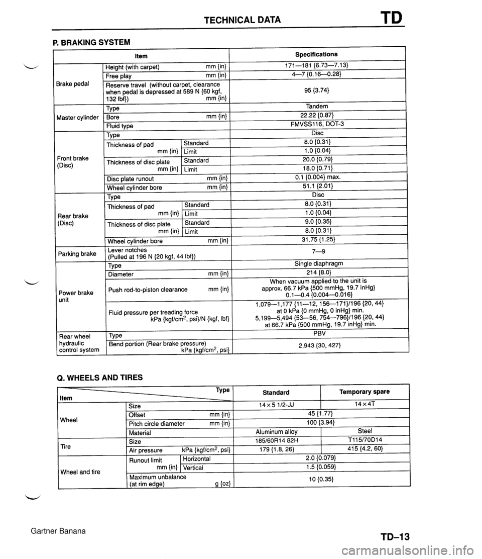
TECHNICAL DATA TD P. BRAKING SYSTEM 3rake pedal Waster cylinder 'ront brake :Disc) Rear brake [Disc) Parking brake Power brake unit Rear wheel hydraulic control system -. . . . . Free play mm {in) I 4--7 {0.16--0.28) Item Heiaht (with car~et) mm {in) Reserve travel (without carpet, clearance when pedal is depressed at 589 N (60 kgf, Specifications 171-1 81 {6.73-7.13) . ,~ I Bore mm {in} I 22.22 (0.87) 132 Ibi)) mm {in) 1 Tv~e Tandem . . Fluid type Type Disc plate runout mm {in) [ 0.1 {0.004) max. Wheel cvlinder bore mm {in) I 51.1 i2.011 . . FMVSS116, DOT-3 Disc ~hickness of pad mm {in) Thickness of disc plate mm {in) I I . . Wheel cylinder bore mm {in) I 31.75 (1.25) Standard Limit .%mhd Limit Lever notches 1 7 n 8.0 I0.31) 1 .O (0.041 20.0 {0.79) 18.0 {0.71} . . Disc 8.0 {0.31) 1 .O i0.04) 9.0 10.35) . , TY pe Thickness of pad mm {in) Thickness of disc plate Tvoe I Sinale diawhraam Standard Limit &mdard mm {in) (Pulled at 196 N (20 kgf, 44 Ibf)) ,r- I " . - Diameter mm {in) I 21 4 (8.0) Limit 1-3 Push rod-to-piston clearance mm (in) When vacuum applied to the unit is approx. 66.7 kPa (500 mmHg, 19.7 inHg} 0.1-0.4 (0.004--0.016) Fluid pressure per treading force kPa {kgf/cm2, psi)/N {kgf, Ibf) Tv~e Q. WHEELS AND TIRES 1,079-1,177 {ll-12, 15&171)/196 (20,441 at 0 kPa 10 mmHg, 0 inHg) min. 5,199~5,494 {53-56, 754--796)/196 {20, 44) at 66.7 kPa (500 mmHg, 19.7 inHg} min. PBV Bend portion (Rear brake pressure) kPa {kgf/cm2, psi) 2,943 {30,427) Wheel Temporary spare 14x4T TY Pe ltem 1 Size Standard 14x5 112-JJ Offset mm {in) Pitch circle diameter mm {in) Material Tire Wheel and tire I 45 {I .77) 100 (3.94) Aluminum allov Steel Size Air pressure kPa {kgf/cm2, psi) 185/60R14 82H 179 11.8, 26) Runout limit mm {in) 1 TI 1 5/70D1 4 41 5 (4.2, 60) Horizontal Vertical 2.0 {0.079) 1.5 10.059) 10 (0.35) Maximum unbalance (at rim edge) 9 {oz) Gartner Banana