Page 1082 of 1708
u HEATER HEATER CONTROL UNIT Removal 1 Installation 1. Remove in the order shown in the figure. 2. Install in the reverse order of removal. 1. Center console 2. Vent outlet 3. Center panel assembly 4. Heater control unit Adjustment . . . . . . . . . . . . . . . . . . page U-22 Gartner Banana
Page 1083 of 1708
HEATER u Disassembly 1 Assembly 1. Disassemble in the order shown in the figure. 2. Assemble in the reverse order of disassembly. 1. Air intake wire 5. Mode lever Adjustment .................. page U-22 6. Temperature-control lever 2. Airflow mode wire 7. Fan switch and ACS u Adjustment .................. page U-22 Inspection ................... page U-22 3. Air mix wire 8. Panel Adjustment .................. page U-22 9. Switch body 4. RECIFRESH lever Gartner Banana
Page 1084 of 1708

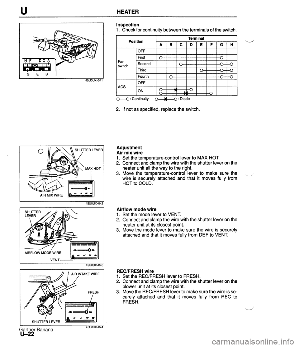
u HEATER I_-K' AIR MIX WlRE -/ AIRFLOW MODE WlRE VENT bm -:JJ 45UOUX-04 AIR INTAKE WlRE / SHUTTER LEVER 45uoux-041 U-22 Inspection 1. Check for continuity between the terminals of the switch. Fan switch ACS Position I I I I I I I I OFF I I Terminal A~B~C~D~E~F~G~H I 1-1 I I I 1- 1- OFF First Second M: Continuity 0-0: Diode 2. If not as specified, replace the switch. Third 0 -0 0 Adjustment Air mix wire 1. Set the temperature-control lever to MAX HOT. 2. Connect and clamp the wire with the shutter lever on the heater unit all the way to the right. 3. Move the temperature-control lever to make sure the -, wire is securely attached and that it moves fully from HOT to COLD. Airflow mode wire 1. Set the mode lever to VENT. 2. Connect and clamp the wire with the shutter lever on the heater unit at its closest point. 3. Move the mode lever to make sure the wire is securely attached and that it moves fully from DEF to VENT. 0 RECIFRESH wire 1. Set the REC/FRESH lever to FRESH. 2. Connect and clamp the wire with the shutter lever on the blower unit at its closest point. 3. Move the RECJFRESH lever to make sure the wire is se- curely attached and that it moves fully from REC to FRESH. u 0 0-4 Gartner Banana
Page 1092 of 1708
u AIR CONDITIONER COOLING UNIT Removal 1 Installation 1. Discharge the refrigerant system. 2. Remove the glove compartment. (Refer to section S.) il 3. Remove in the order shown in the figure. Immediately plug all open fittings to keep moisture out of the system. 4. Install in the reverse order of removal. Position the unit so that its connections match those of the heater unit and blower unit. Apply clean compressor oil to the O-rings before connecting the fittings; do not ap- ply compressor oil to the fitting nuts. Tightening torque Inlet pipe: 10-19 N-m (1.0-2.0 kgfsm, 8-14 ft-lbf} Outlet pipe: 20-29 N-m (2.0-3.0 kgf-m, 15--21 ft-lbf} 5. Charge the refrigerant system. (Refer to page U-25.) 7.910.7 N.m {EO-110 kgfmn, 69.5-95.4 In4bf} 45uoux-071 1. Cooling unit 2. Sealing plate Disassembly / Assembly . . . . . . page U-31 U-30 Gartner Banana
Page 1109 of 1708
TECHNICAL DATA MEASUREMENTS ......................... TD- 2 ................................... ENGINE TD- 2 .................... LUBRICATION SYSTEM TD- 5 ........................ COOLING SYSTEM TD- 5 FUEL AND EMISSION CONTROL SYSTEMS . TD- 6 ENGINE ELECTRICAL SYSTEM ............. TD- 7 .................................. CLUTCH TD- 7 .................. MANUAL TRANSMISSION TD- 8 AUTOMATIC TRANSMISSION ............... TD- 9 ....................... PROPELLER SHAFT TD-11 FRONT AND REAR AXLES ................. TD-12 STEERING SYSTEM ....................... TD-12 BRAKING SYSTEM ........................ TD-13 WHEELS AND TIRES ...................... TD-13 ............................. SUSPENSION TD-14 BODY ELECTRICAL SYSTEM ............... TD-15 HEATER AND AIR CONDITIONING SYSTEM . TD-15 STANDARD BOLT AND NUT TIGHTENING ................................. TORQUE TD-15 45UTDX-001 Gartner Banana
Page 1123 of 1708

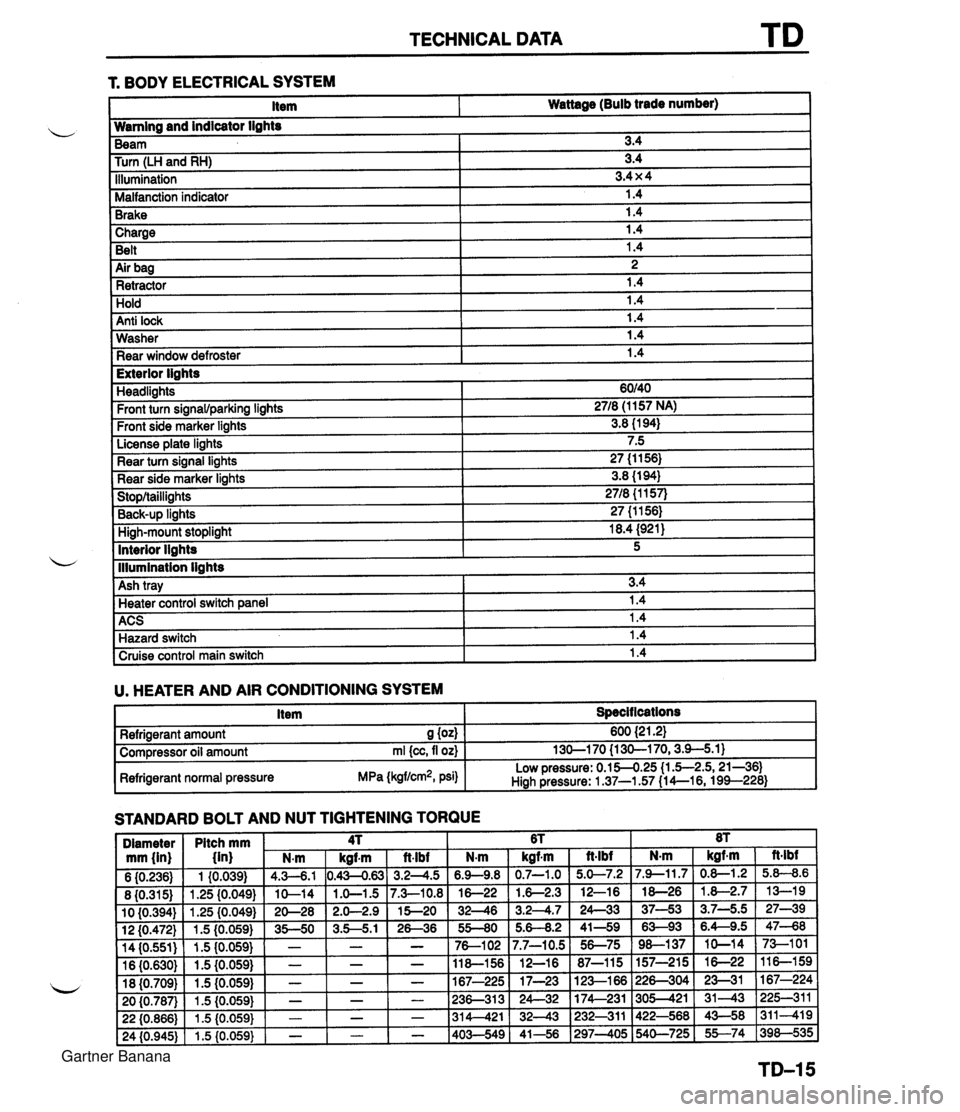
TECHNICAL DATA 1 Charge I 1.4 Belt 1.4 r. BODY ELECTRICAL SYSTEM 1 Air bag I 2 1 Retractor 1.4 Item Wattage (Bulb trade number) Hold Anti lock Wamlng and indicator lights 1.4 1.4 Washer Rear window defroster Beam Turn (LH and RH) Illumination Malfanction indicator Brake 1.4 1.4 I Exterior lights 3.4 3.4 3.4 x 4 1.4 1.4 Headlights Front turn signawparking lights Front side marker lights License plate lights Rear turn signal lights Rear side marker lights Stop/taillights Back-UP linhts High-mount stoplight I 18.4 (921) ACS 1 1.4 Hazard switch 1.4 60140 2718 (1 157 NA) 3.8 (1 94) 7.5 27 (1 1 56) 3.8 (1 94) 2718 {I 157) 27 (1 1561 Interior llahts - I lllumination lights I Cruise control main switch I 1.4 I 5 Ash tray U. HEATER AND AIR CONDITIONING SYSTEM I Item I Specit lcations I 3.4 Heater control switch ane el I 1.4 STANDARD BOLT AND NUT TIGHTENING TORQUE Refrigerant amount S (04 Compressor oil amount rnl {cc, fl oz) Refrigerant normal pressure MPa (kgflcm2, psi) 600 {2 1.21 130-1 70 {I 30-1 70,3.9-5.1) Low pressure: 0.154.25 (1 .5-2.5,21-361 Hiah Pressure: 1 37-1.57 (1 4--16, 199--228) Gartner Banana
Page 1362 of 1708

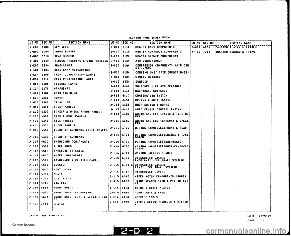
SECT ION NAME INDEX (my) - LO a NO * - ... - a 2-C03 2-E03 2-H03 2-403 2-KO3 2-1.03 2-CO4 2-E04 2-H04 2-104 2- JOG ?-KO4 2-M04 ?-NO4 9-CO4 ?-LO5 2-8 0% ?-KO5 ?-NO!, 7-CO6 ?*C47 i?-107 ?*f-d7 ?-GO I ?- 109 ,!-LO I Z-catj il- t. 0 a 2 .. f' fl g4 ?-GO9 ;,. JO9 ?-MQY ? il'j ? CII --- - - SEC .#I ---..- 0900 5000 5910 8030 5100 5103 $105 5110 5120 5170 5180 5230 5260 5310 5520 5539 5340 5370 5580 53 YO 5500 5570 55.10 5!>40 5560 55 "0 5588 5 IOU 5790 '; 19'. 5flOti !,bSB !J n c* u LlbIJ . ---..- - - --- SECfION NAME -----.- ------------------ ..--- KEY SETS FRONT BUNPER REAR EUHPER WINDOW HOULDING L COWL GRILLES HEAD LANPS HEAD LAHP RE T RACY ORS FRONT CONBINITION Lanes REAR COHBINATIOH LAHPS L ALENSE LAHPS BRNAMM3S REAR FIWISWER BONNET TRUNK LIB FWDNT PANELS FEIiDER P WHEEL APRON PANELS 3PCU L COWL PANELS SiUE PANELS {'!.OUR PANELS, FLCOR AYTACWHEHTS (HDCC GOVEAS 1 FLOOR AVYACHHEHTS DASHEOARD EOU IPMENI 5 nf VCR NttUD SPEEDOM TCW CADI.[; nt 1 ER CONPONE ws DASHBOAKU 6 WI LATLb PAKl S COHSOLC. VLUTILATOSI St.AI'S %CAI IC'ITS AIR OhC FblOlil li00k'$ F WLlh 'l !WOH Wt't:NAN I TUUHI 1)ouu IHlnS 1 WELAICL, PAW 1s - SEC * N( -----a 6110 6115 6 120 6130 6160 6190 6300 6330 6600 6610 661 1 6638 6635 6640 6600 6662 670U &7C 1 6707 6703 6784 6 ?i!U 6720 1 6730 6 760 ba20 6140 ~uen tB1U bVQU SECTION NAHE HEATER UNIT COMPONENTS HEATER CONTROLS COMPONENTS HEATER BL OWER COHPONENT S AIR CONDITIONER COMPRESSOR COHFONENTS (AIR CON DIT JlrNEiO COOLING UI\'TS (AIR COHDITIOHEW) WINDOW GLASSES SUNROOF SWITCHES C RFtAVS (ENGINE) DASHBOARD SWlTCHES COHBINATIOM SWITCH RELAYS L UNIT (BODY) DOOR SWITCH & HDRWS AUTO CRUISE CONTROL SYSTEH AUDIO SYSTEMS (RADIO & TAPE W. CK 1 AUDIO SYSTFffS (ANTENNA 6 SPEAK El?) NIP t He HARNESSES(FRON1 L REAR ) WlW iNG HARNESS CL.AHPS UtHaSH1EL.D W4SHER ANT1 LJCI BRAKE SYSTEH) WIHDSHIELU WASHER (AH71 LOCK BRAKE SYSTEM) UINUSHIELD WIPERS FRONT hEAD$Y TWIN & PIMY TRl n s FLOOR HATS L PAW QUARTER WINDOW L VRIHS LA I L Olr HI).. AUHAOd* I1 3 Gartner Banana
Page 1529 of 1708

SECTION NAME KEY SETS FRONT BUHPER REAR SUNPER WINDOW rlOULBIHG L COWL GRILLES HEAD LAMPS IIEAD LAHP RE 1 RACTORS FRONT COHBINATION LAWS REAR CUHBlNATIOH LAHPS L ICE HOE LAWS ORNhHENTS REAR F f Hf Ci+CR BONNET TRUNK 110 f RWT PANEL S FLHOEW & WHfkL APWOt4 P4NkL!$ LUSH & COWL PANELS SIDE PANELS FLOOR PANELS F LOOR ATTACHHENTS (HOLE COVERS ) HkTER HOOD SCf 600NC TCH CAB1.k RC 1 ER COMPONENTS SECTION nAnE ---------_L---_-----__________L_______I__________________L_______I__________________L_______I________-__________L_______I__________________L_______I__________________L_______I________ HEAI'ER Wit COMPONENTS HEATER CONTROLS COHPONENf S HEATER BLOWER COWPONENTS AIR CONBlTXOMR COHPRESSOR COHPONENTS (AIR CDh DITIONER) COOLING UNIT (AIR CO#DlTZONERI WINDOW GLASSES SUNRtOF SWiTCMES L RELAvC (ENGINE) DASMIOAWD SWITCHES CO~bfNAI~OH SWlfCiI RELAYS L UNIT i8OBV) DOOR SWITCH L HORNS AUTO CRUISE CONTROL C't SIGH AUDIO SYSTEHS (ANTENNA C WEAK ER MIWBSH2El.D YASHCK (U/U ANTI LUCI MAKC SYSICI) 7250 QUARTER WINCOW L TRIHS Gartner Banana