Page 1085 of 1708
AIR CONDITIONER U AIR CONDITIONER PREPARATION i, SST I I c STRUCTURAL VIEW 00007-10331 Stopper, magnetic clutch 4992-02-020 Pressure plate remover For removal and installation of magnetic clutch For removal of pressure plate 1. Cooling unit 5. Condenser fan relay Removal I Installation ......... page U-30 Inspection ................... page U-37 Disassembly I Assembly ...... page U-31 6. AX: compressor 2. Condenser Removal I Installation ......... page U-38 Removal I Installation ......... page U-33 Disassembly I Assembly ...... page U-41 w 3. Receiver drier 7. Magnetic clutch Removal / Installation ......... page U-33 Disassembly / Assembly ...... page U-39 4. A/C relay Inspection ................... page U-37 Gartner Banana
Page 1090 of 1708

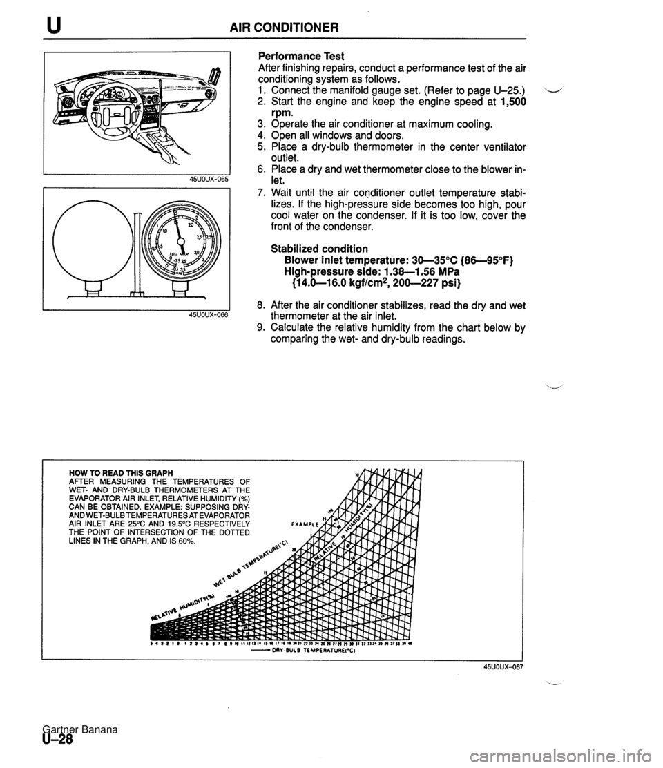
u AIR CONDITIONER Performance Test After finishing repairs, conduct a performance test of the air conditioning system as follows. 1. Connect the manifold gauge set. (Refer to page U-25.) 2. Start the engine and keep the engine speed at 1,500 rpm. 3. Operate the air conditioner at maximum cooling. 4. Open all windows and doors. 5. Place a dry-bulb thermometer in the center ventilator outlet. 6. Place a dry and wet thermometer close to the blower in- let. 7. Wait until the air conditioner outlet temperature stabi- lizes. If the high-pressure side becomes too high, pour cool water on the condenser. If it is too low, cover the front of the condenser. Stabilized condition Blower inlet temperature: 30-35°C (86-95°F) High-pressure side: 1.38-1.56 MPa (1 4.0-1 6.0 kgflcm*, 200-227 psi) 8. After the air conditioner stabilizes, read the dry and wet thermometer at the air inlet. 9. Calculate the relative humidity from the chart below by comparing the wet- and dry-bulb readings. Gartner Banana
Page 1091 of 1708

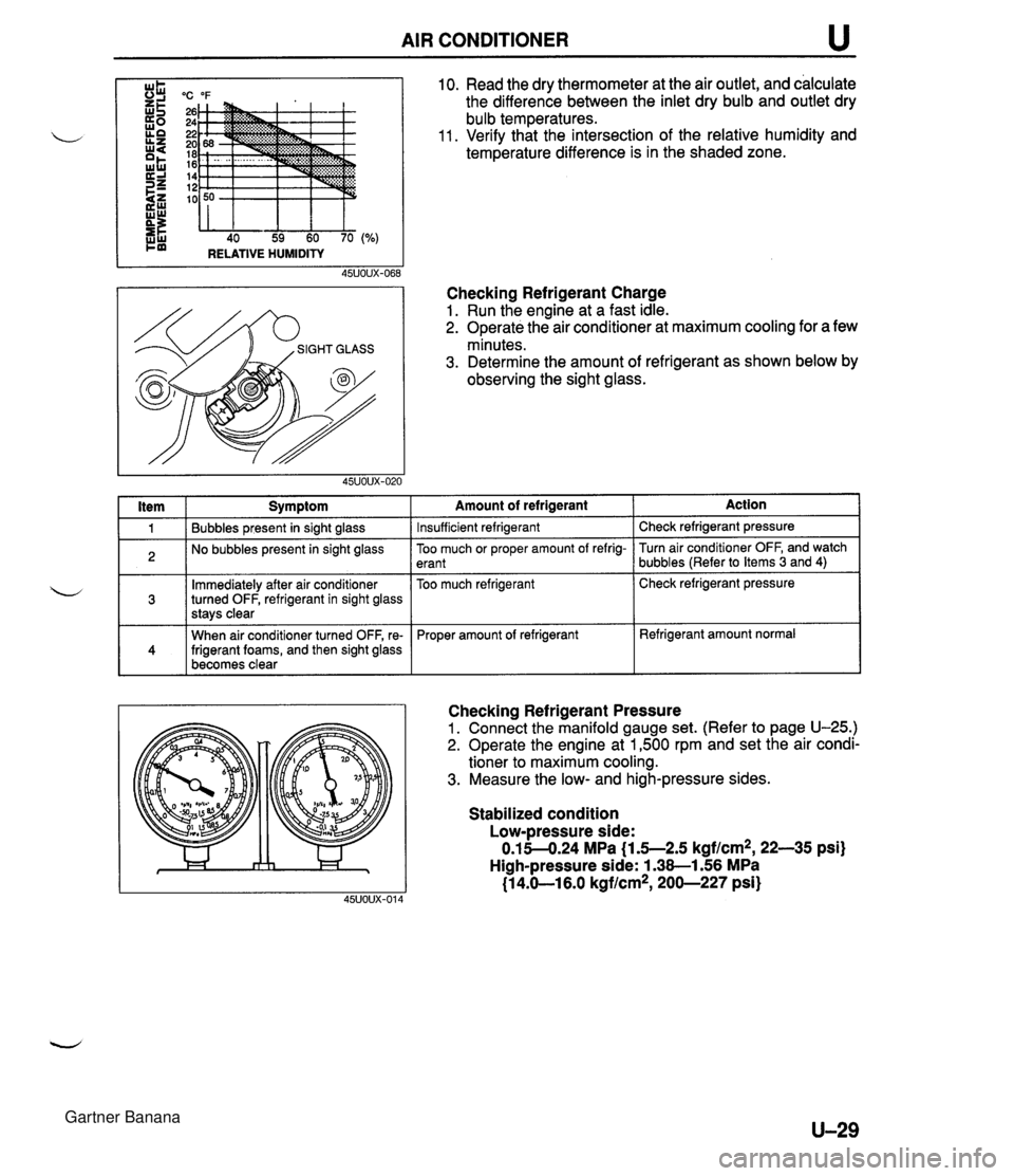
AIR CONDITIONER u "C "F 26 24 22 20 18 16 14 12 10 40 59 60 70 RELATIVE HUMIDITY I ltem I Symptom 10. Read the dry thermometer at the air outlet, and calculate the difference between the inlet dry bulb and outlet dry bulb temperatures. 11. Verify that the intersection of the relative humidity and temperature difference is in the shaded zone. Checking Refrigerant Charge 1. Run the engine at a fast idle. 2. Operate the air conditioner at maximum cooling for a few minutes. 3. Determine the amount of refrigerant as shown below by observing the sight glass. 1 Bubbles present in sight glass 2 No bubbles present in sight glass Immediately after air conditioner turned OFF, refrigerant in sight glass stavs clear 141 When air conditioner turned OFF, re- frigerant foams, and then sight glass becomes clear -- Amount of refrigerant Insufficient refrigerant Action Check refrigerant pressure -- Too much or proper amount of refrig- erant Too much refrigerant Checking Refrigerant Pressure 1. Connect the manifold gauge set. (Refer to page U-25.) 2. Operate the engine at 1,500 rpm and set the air condi- tioner to maximum cooling. 3. Measure the low- and high-pressure sides. Turn air conditioner OFF, and watch bubbles (Refer to Items 3 and 4) Check refrigerant pressure Proper amount of refrigerant Stabilized condition Low-pressure side: 0.15-4.24 MPa {I .5--2.5 kgf/cm2, 22-35 psi) High-pressure side: 1.38-1.56 MPa (1 4.61 6.0 kgflcm*, 200-227 psi) Refrigerant amount normal Gartner Banana
Page 1092 of 1708
u AIR CONDITIONER COOLING UNIT Removal 1 Installation 1. Discharge the refrigerant system. 2. Remove the glove compartment. (Refer to section S.) il 3. Remove in the order shown in the figure. Immediately plug all open fittings to keep moisture out of the system. 4. Install in the reverse order of removal. Position the unit so that its connections match those of the heater unit and blower unit. Apply clean compressor oil to the O-rings before connecting the fittings; do not ap- ply compressor oil to the fitting nuts. Tightening torque Inlet pipe: 10-19 N-m (1.0-2.0 kgfsm, 8-14 ft-lbf} Outlet pipe: 20-29 N-m (2.0-3.0 kgf-m, 15--21 ft-lbf} 5. Charge the refrigerant system. (Refer to page U-25.) 7.910.7 N.m {EO-110 kgfmn, 69.5-95.4 In4bf} 45uoux-071 1. Cooling unit 2. Sealing plate Disassembly / Assembly . . . . . . page U-31 U-30 Gartner Banana
Page 1098 of 1708
u AIR CONDITIONER CONDENSER FAN Removal / Installation 1. Disconnect the negative battery cable. 2. Disconnect the cooling fan and condenser fan connector. 3. Remove the bolts. 4. Remove in the order shown in the figure. 5. Install in the reverse order of removal. 1. Cooling fan 2. Condenser fan Inspection 1. Disconnect the condenser fan connector. 2. Verify that the condenser fan motor runs when connect- ing battery positive voltage to terminal A and grounding terminal B. B+: Battery positive voltage u 45UOUX-082 U-36 Motor operation Yes Connection B+ A GND B Gartner Banana
Page 1109 of 1708
TECHNICAL DATA MEASUREMENTS ......................... TD- 2 ................................... ENGINE TD- 2 .................... LUBRICATION SYSTEM TD- 5 ........................ COOLING SYSTEM TD- 5 FUEL AND EMISSION CONTROL SYSTEMS . TD- 6 ENGINE ELECTRICAL SYSTEM ............. TD- 7 .................................. CLUTCH TD- 7 .................. MANUAL TRANSMISSION TD- 8 AUTOMATIC TRANSMISSION ............... TD- 9 ....................... PROPELLER SHAFT TD-11 FRONT AND REAR AXLES ................. TD-12 STEERING SYSTEM ....................... TD-12 BRAKING SYSTEM ........................ TD-13 WHEELS AND TIRES ...................... TD-13 ............................. SUSPENSION TD-14 BODY ELECTRICAL SYSTEM ............... TD-15 HEATER AND AIR CONDITIONING SYSTEM . TD-15 STANDARD BOLT AND NUT TIGHTENING ................................. TORQUE TD-15 45UTDX-001 Gartner Banana
Page 1113 of 1708

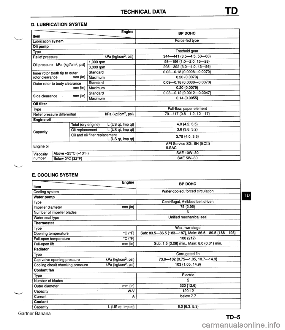
TECHNICAL DATA D. LUBRICATION SYSTEM - Engine ltem BP DOHC - -. Lubrication system Force-fed type E. COOLING SYSTEM Trochoid gear 344-41 I3.5--4.5,s-31 9&l96 {I .&2.0, 15--28) 295-392 {3.0-4.0,43-56) 0.02-0.1 8 {0.000&0.0070) 0.20 {0.0079) 0.09-0.18 (0.0036-0.0070) 0.20 {0.0079) 0.03-0.1 2 {0.0012-0.0047) 0.14 (0.0055) TY pe Relief pressure kPa {kgf/cm2, psi) Oil pressure kPa {kgf/cm2, psi) Inner rotor tooth tip to outer rotor clearance mm {in) Outer rotor to body clearance mm {in) Side clearance mm {in) Water seal type I Unified mechanical seal Thermostat 1,000 rpm 3,000 rpm Standard Maximum Standard Maximum Standard Maximum Oil filter Engine ltem - - Cooling system . . Impeller diameter mm {in) Number of impeller blades Type Relief pressure differential kPa {kgf/cm2, psi) BP DOHC Water-cooled, forced circulation - 75 i2.95) 6 Full-flow, paper element 74-1 17 {0.&1.2, 12-1 7) TY pe . ., . . . - Radiator I Water pump Wax, two-stage v. . . Full-open temperature "c {OF) Full-open lift mm {in) Engine oil TVD~ O~enina tem~erature "C con I Sub: 83.5-86.5 U83-187). Main: 86.5-89.5 (1 88-1 931 100 (21 2) Sub: 1.5 (0.06) min., Main: 8.0 (0.31) min. -. . - . . Cooling circuit checking pressure kPa {kgflcmz, psi) I 103 {I .05, 14.9) I Centrifugal, V-ribbed belt driven TY pe I Coolant fan I 4.0 (4.2, 3.5) 3.6 {3.8,3.2) 3.75 (4.0, 3.3) API Service SG, SH (ECII) ILSAC Capacity Corrugated fin viscosity Above -25°C (-1 3°F) SAE 1 OW-30 number Below 0°C {3Z°F) SAE 5W-30 Total (dry engine) L {US qt, Imp qt) Oil replacement L {US qt, Imp qt) Oil and oil filter replacement L {US qt, Imp qtl Cap valve o~enina pressure kPa {krrf/cm2, psi} 1 73.6--102 {0.75--1.05, 10.7-14.91 Capacity W-V I 120-1 2 Current A 1 below 7.7 Engine oil Type Number of blades Outer diameter mm {in) Coolant Capacity L {US qt, Imp qt) I 6.0 {6.3,5.3) Electric 5 320 (1 2.61 Gartner Banana
Page 1256 of 1708

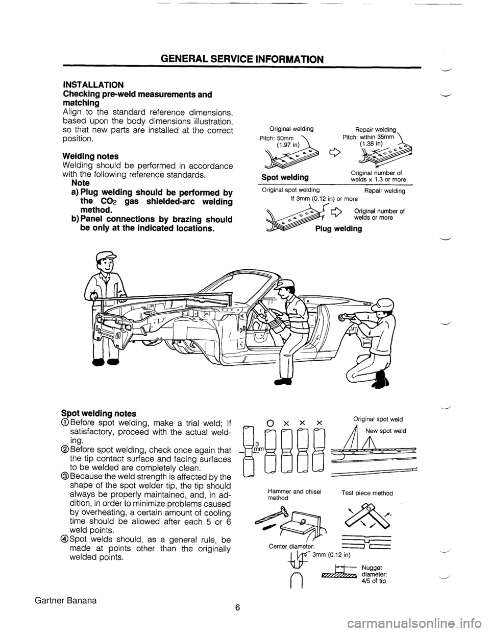
GENERAL SERVICE INFORMATION d INSTALLATION Checking pre-weld measurements and matching Align to the standard reference dimensions, based upon the body dimensions illustration, so that new parts are installed at the correct position. Welding notes Welding should be performed in accordance with the following reference standards. Note a) Plug welding should be performed by the CO2 gas shielded-arc welding method. b) Panel connections by brazing should be only at the indicated locations. Original welding Repair welding Pitch: 50mm Pitch: within 35mm (1.97 in) Original number of Spot welding welds x 1.3 or more Original spot welding Repair welding If 3rnm (0.12 in) or more Original number of welds or more Plug welding Spot welding notes OXXX Original spot weld @Before spot welding, make a trial weld; If satisfactory, proceed with the actual weld- ing. the tip contact surface and facing surfaces ~~[l/jLJL!= @Before spot welding, check once again that - Em -- to be welded are completely clean. @Because the weld strength is affected by the / shape of the spot welder tip, the tip should always be properly maintained, and, in ad- Hammer and chisel Test piece method method dition, in order to minimize problems caused by overheating, a certain amount of cooling time should be allowed after each 5 or 6 weld points. @Spot welds should, as a general rule, be & U made at points other than the originally Center diameter: lr welded points. w 3mm (0.12 in) n 2 Yi'%%Lr: 415 of tip Gartner Banana