Page 1100 of 1708
u AIR CONDITIONER A/C COMPRESSOR Removal / Installation 1. Raise the front of the vehicle at least 300 mm (11.8 In) and support it on safety stands. 2. Discharge the refrigerant system. i~ 3. Remove the splash shield and air guide. 4. Remove in the order shown in the figure. Immediately plug and open fittings to keep moisture out of the system. 5. Install in the reverse order of removal. Apply clean compressor oil to the O-rings before connecting the fittings; do not apply compressor oil to the fitting nuts. . 6. Adjust the belt tension. (Refer to page U-46.) 7. Install the air guide and splash shield. 8. Charge the refrigerant system. (Refer to page U-25.) 45uoux-086 i/ 1. Flexible hose 3. Magnetic clutch 2. AIC compressor Disassembly / Assembly . . . . . . page U-39 Disassembly / Assembly . . . . . . page U-41 Gartner Banana
Page 1103 of 1708
AIR CONDITIONER u A/C compressor housing @ REPLACE 45UOUX4 1. Discharge valve body 4. Front housing 2. Discharge valve plate 5. Shaft seal plate 3. Discharge valve 6. Shaft seal 7. Rear housing 8. Compressor body 1. Measuring of compressor oil amount Measure the amount of the compressor oil which is in the A/C compressor. 2. Removal of discharge valve body (1) Remove the discharge valve body installation through bolts. Gartner Banana
Page 1105 of 1708
AIR CONDITIONER u BUSHING 5. Removal of shaft seal Remove the shaft seal from the shaft. Do not disas- semble the compressor body. 6. Removal of shaft seal plate Remove the shaft seal plate by using a suitably sized bushing. 7. Installation of shaft seal plate Install the shaft seal plate by using a suitably sized bush- ing. 8. Installation of shaft seal (1) Lubricate the shaft seal with the compressor oil. (2) Install the shaft seal on the shaft. 9. Installation of front and rear housings (1) Install the new gaskets and pin on the compressor body. Gartner Banana
Page 1107 of 1708
AIR CONDITIONER u O-RING (2) Tighten the discharge valve body installation through bolts. Tightening torque: 10.8 N-m (110 kgf-cm, 95.5 in-lbf) (3) Tighten the discharge valve body installation bolts. Tightening torque: 10.8 N-m (110 kgf-cm, 95.5 in-lbf) 1 3. Pour compressor oil (ND-OILS) Pour compressor oil into the A/C compressor. Compressor oil amount: Same amount as drained, plus 20 ml(20 cc, 0.6 fl or) 14. Installation of service valve (1) Apply the compressor oil to the new O-rings. (2) Install the service valves to the compressor and tight- en the installation bolts. Tightening torque: 12.3 N-m (125 kgf-cm, 109 in-lbf) Gartner Banana
Page 1108 of 1708

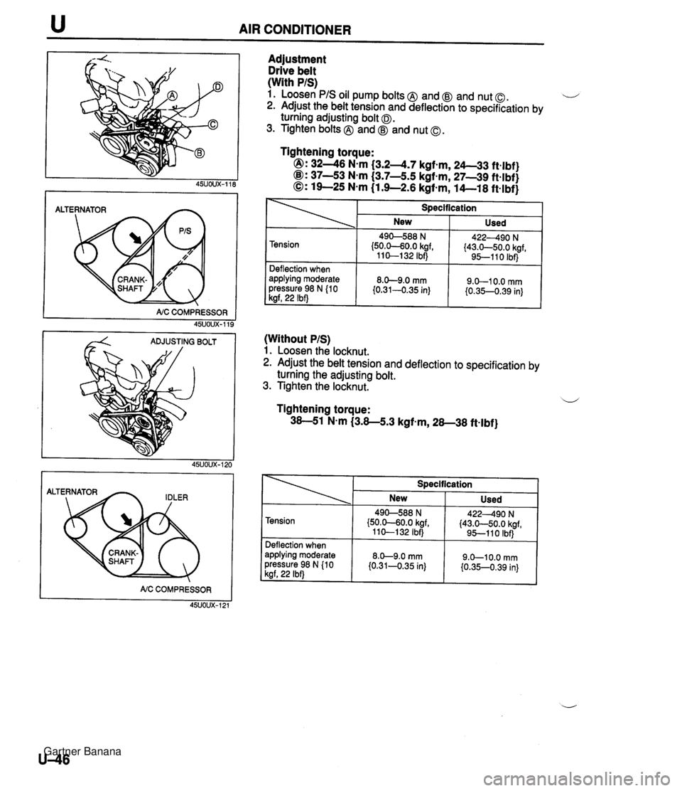
u AIR CONDITIONER I NC COMPRESSOR 45UOUX-119 Adjustment Drive belt (With PIS) 1. Loosen PIS oil pump bolts @ and @ and nut 0. ...-' 2. Adjust the belt tension and deflection to specification by turning adjusting bolt 0. 3. Tighten bolts @ and @J and nut 0. (Without PIS) 1. Loosen the locknut. 2. Adjust the belt tension and deflection to specification by Tightening torque: @I: 3246 N.m (3.2-4.7 kgf-m, 24-33 ftelbf) @I: 37-53 Nem (3.7-5.5 kgf-m, 27-39 ft-lbf) 0: 19-25 N.m (1 3-2.6 kgf-m, 14--18 ft-lbf) turning the adjusting bolt. 3. Tighten the locknut. 1 Tension t Deflection when applying moderate pressure 98 N {lo 1 kgf, 22 Ibf) Tightening torque: 38-51 N-m (3.8-5.3 kgf-m, 28-38 ft-lbf) Specification NC COMPRESSOR 45UOUX-121 New 490-588 N (50.0-60.0 kgf, 11 0-1 32 Ibf) 8.0-9.0 mm {0.31-0.35 in) Specification Used 422490 N (43.0-50.0 kgf, 9!5-110 Ibf) 9.0-1 0.0 mm I0.35--0.39 in) New Used Tension Deflection when applying moderate pressure 98 N (10 kgf, 22 Ibf) 490-588 N {50.0-60.0 kgf, 110-132 IbfJ 8.0-9.0 mm i0.31-0.35 in) 422490 N (43.0-50.0 kgf, 95-1 1 0 Ibf) 9.0-1 0.0 mm I0.35-0.39 in) Gartner Banana
Page 1111 of 1708

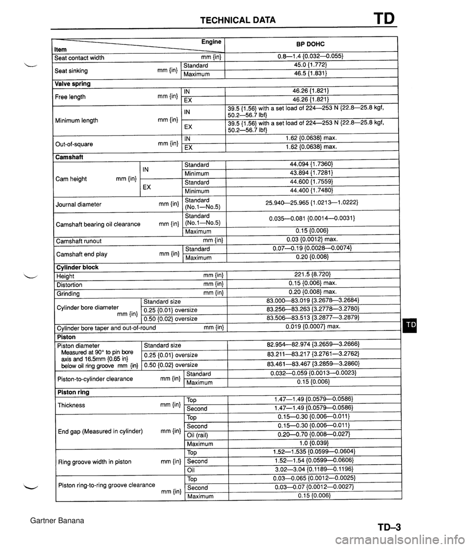
TECHNICAL DATA TD BP DOHC 0.8-1.4 {0.0324.055) 45.0 (1.772) 46.5 11.831) Engine Item Seat contact width mm {in) Valve spring End gap (Measured in cylinder) mm {in) Seat sinking mm {in) Free length mm {in) Minimum length mm {in) Out-of-square mm {in) Camshaft bearing oil clearance mm {in} Ring groove width in piston mm {in) Standard Maximum Piston ring-to-ring groove clearance mm {in) IN EX IN EX IN EX Standard (No.1-No.5) Maximum 46.26 (1.821) 46.26 (1.821) 39.5 {I 56) with a set load of 224--253 N I22.8-25.8 kgf, 50.2-56.7 Ibf) 39.5 (1 56) with a set load of 224-253 N I22.8-25.8 kgf, 50.2-56.7 Ibf) 1.62 (0.0638) max. 1.62 (0.0638) max. Camshaft 0.035-0.081 {0.0014-0..0031) 0.1 5 (0.006) 0.03 {0.001 2) max. 0.07-0.1 9 {0.002~.0074) 0.20 {0.008) Camshaft runout mm {in) TOP Second Cam height mm {in) Camshaft end play mm (in) 0.15-0.30 {0.006-0.011) 0.15-0.30 {0.006--0.011) -- - I Standard Minimum Standard Minimum Standard (No.1-N0.5) IN EX Standard Maximum Oil (rail) Maximum I 1 .O {0.039) 44.094 {I .7360) 43.894 {I .7281) 44.600 11.7559) 44.400 {I .7480) 25.940-25.965 11.021 3-1.0222) Journal diameter mm Iin) Cylinder block 0.20-0.70 {0.00&0.027) TOD Second Oil 1.52-1 535 {0.0594--0.0604) 1.52-1.54 (0.0599--0.0606} 3.02-3.04 f0.11894.1196) Second Maximum 221.5 (8.720) 0.1 5 {0.006) max. 0.20 {0.008) max. 83.00&83.019 i3.2678-3.2684) 83.25683.263 {3.277&3.2780) 83.508-883.51 3 (3.2877-3.2879) 0.01 9 {0.0007} max. Height mm {in) Distortion mm (in) Grinding mm {in} 0.03-0.07 {0.00124.0027) 0.1 5 {0.006) Cylinder bore diameter mm {in] Standard size 0.25 {0.01) oversize 0.50 (0.02) oversize Piston , Cylinder bore taper and out-of-round mm {in) 82.95442.974 i3.2659--3.2666) 83.211-43.21 7 (3.2761-3.2762) 83.461-83.467 (3.2853--3.2860) 0.0324.059 {0.001 3--0.0023) 0.15 (0.006) Piston diameter Measured at 90" to Pin bore axis and 16.5mm i0.65 in) below oil ring groove mm {in) Standard size 0.25 {0.01) oversize 0.50 (0.02) oversize Piston ring Piston-to-cylinder clearance mm (in) Thickness mm {in) Standard Maximum TOP 1.47-1 -49 (0.0579--0.0586} Second 1.47-1.49 {0.0579--0.0586) Gartner Banana
Page 1112 of 1708

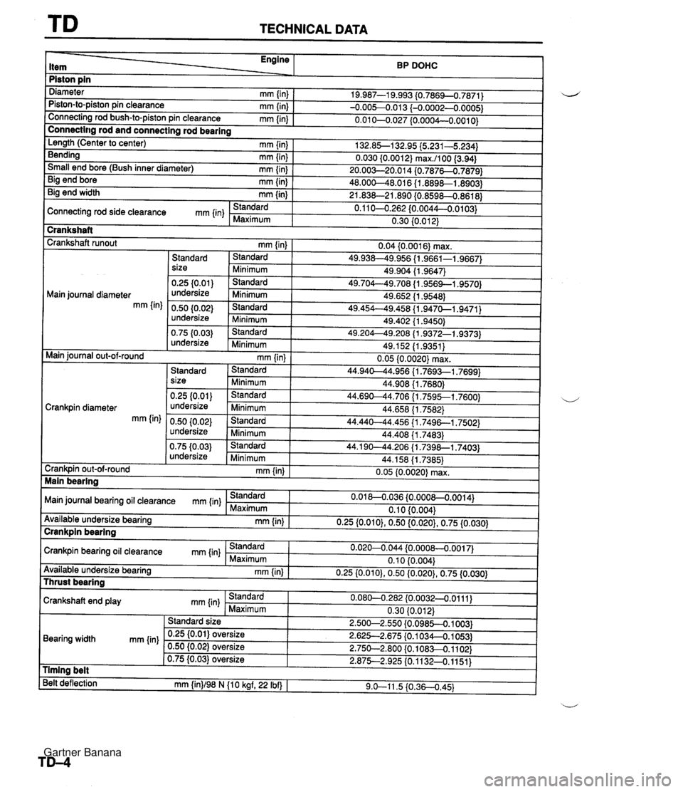
TD TECHNICAL DATA item Main journal diameter mm {in) BP DOHC Diameter mm {in) Piston-to-piston pin clearance mm {in) Connecting rod bush-to-piston pin clearance mm (in) Piston pin 19.987-1 9.993 {0.7869-0..7871) -0.00~0.013 {-0.0002-0.0005) 0.01 0-0.027 {0.0004--0.0010} I Main iournal out-of-round - . - . . - -. - size 0.25 {o.oi) undersize 0.50 (0.02) undersize 0.75 I0.03) undersize mm (in) I 0.05 10.0020) max. I Connectir~g rod and connecting rod bearing . L, . -- 2 - 1 Standard 1 Standard I 44.940-44.956 11.7693--1.7699) Minimum Standard ' Minimum Standard 'Minimum Standard Minimum 1 size 1 ~inimum I 44.908 11.76801 I 132.8S132.95 I5.231-5.234) 0.030 (0.001 2) max.1100 (3.94) 20.003--20.0 14 {0.78760.7879) 48.000-48.01 6 {I .8898-1.8903) 21.838-21.890 (0.8598-0.8618) 0.1 104.262 {0.0044-0.0103) 0.30 (0.01 2) Length (Center to center) mm {in) Bending mm (in) Small end bore (Bush inner diameter) mm {in) Big end bore mm {in) Big end width mm {in) 49.904 (1.9647) 49.704--49.708 {I $9569--1.9570) 49.652 {I .9548) 49.454--49.458 {I .947&1.9471) 49.402 (1.9450) 49.204--49.208 (1.9372-1.9373) 49.152 11.9351) Cranks haft Crankshaft runout mm (in) I 0.04 {0.0016) max. Standard 1 Standard I 49.938--49.956 (1.9661-1.9667) Connecting rod side clearance mm {in) . Standard Maximum Crankpin diameter mm (in) - -- s- - 8 undersize 0.50 10.02) undersize 44.1 90-44.206 {I .7398-1.7403) 44.158 {I .7385) 0.05 (0.00201 max. 0.75 {0.03) undersize " Main bearina Standard Minimum Main journal bearing oil clearance mm (in) - L~inimum Standard 'Minimum Crankpin out-of-round mm {in} Crankpin bearing oil clearance mm (in) Standard Maximum 44.658 (1.7582) 44.440-44.456 {I .7496-1,7502) 44.408 (1.74831 0.01 8-0.036 {0.0008--0.0014) 0.1 0 {0.004) Available undersize bearing mm (in) Standard Maximum - 0.25 {0.010), 0.50 {0.020), 0.75 (0.030) 0.020-0.044 {0.0008--0.0017) 0.10 {0.004} Available undersize bearing mm {in) Crankpin bearing 0.25 {0.010), 0.50 {0.020), 0.75 (0.030) Thrust bearing Crankshaft end play mm {in) Standard Maximum 0.080-0.282 (0.0032--0.0111) 0.30 (0.012) 2.500-2.550 {0.0985--0.1003) 2.625-2.675 (0.1 034-0.1 053) 2.750-2.800 {0.108H.1102) 2.875-2.925 {0.1132--0.1151) Bearing width mm {in) nming belt Belt deflection mm {in)/98 N (10 kgf, 22 Ibf) I 9.0-11.5 i0.360.45) ~U Standard size 0.25 (0.01) oversize 0.50 {0.02) oversize 0.75 (0.03) oversize Gartner Banana
Page 1113 of 1708

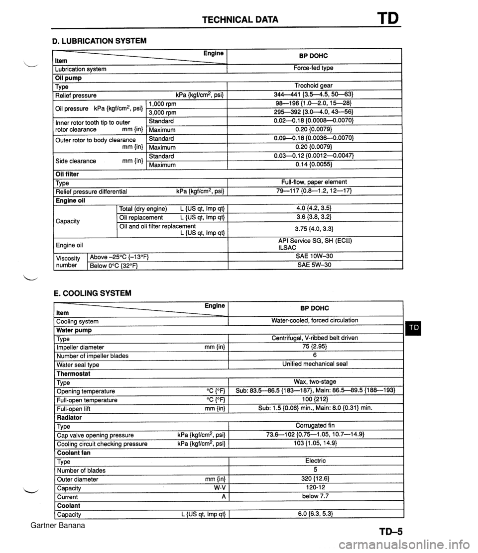
TECHNICAL DATA D. LUBRICATION SYSTEM - Engine ltem BP DOHC - -. Lubrication system Force-fed type E. COOLING SYSTEM Trochoid gear 344-41 I3.5--4.5,s-31 9&l96 {I .&2.0, 15--28) 295-392 {3.0-4.0,43-56) 0.02-0.1 8 {0.000&0.0070) 0.20 {0.0079) 0.09-0.18 (0.0036-0.0070) 0.20 {0.0079) 0.03-0.1 2 {0.0012-0.0047) 0.14 (0.0055) TY pe Relief pressure kPa {kgf/cm2, psi) Oil pressure kPa {kgf/cm2, psi) Inner rotor tooth tip to outer rotor clearance mm {in) Outer rotor to body clearance mm {in) Side clearance mm {in) Water seal type I Unified mechanical seal Thermostat 1,000 rpm 3,000 rpm Standard Maximum Standard Maximum Standard Maximum Oil filter Engine ltem - - Cooling system . . Impeller diameter mm {in) Number of impeller blades Type Relief pressure differential kPa {kgf/cm2, psi) BP DOHC Water-cooled, forced circulation - 75 i2.95) 6 Full-flow, paper element 74-1 17 {0.&1.2, 12-1 7) TY pe . ., . . . - Radiator I Water pump Wax, two-stage v. . . Full-open temperature "c {OF) Full-open lift mm {in) Engine oil TVD~ O~enina tem~erature "C con I Sub: 83.5-86.5 U83-187). Main: 86.5-89.5 (1 88-1 931 100 (21 2) Sub: 1.5 (0.06) min., Main: 8.0 (0.31) min. -. . - . . Cooling circuit checking pressure kPa {kgflcmz, psi) I 103 {I .05, 14.9) I Centrifugal, V-ribbed belt driven TY pe I Coolant fan I 4.0 (4.2, 3.5) 3.6 {3.8,3.2) 3.75 (4.0, 3.3) API Service SG, SH (ECII) ILSAC Capacity Corrugated fin viscosity Above -25°C (-1 3°F) SAE 1 OW-30 number Below 0°C {3Z°F) SAE 5W-30 Total (dry engine) L {US qt, Imp qt) Oil replacement L {US qt, Imp qt) Oil and oil filter replacement L {US qt, Imp qtl Cap valve o~enina pressure kPa {krrf/cm2, psi} 1 73.6--102 {0.75--1.05, 10.7-14.91 Capacity W-V I 120-1 2 Current A 1 below 7.7 Engine oil Type Number of blades Outer diameter mm {in) Coolant Capacity L {US qt, Imp qt) I 6.0 {6.3,5.3) Electric 5 320 (1 2.61 Gartner Banana