Page 351 of 1708

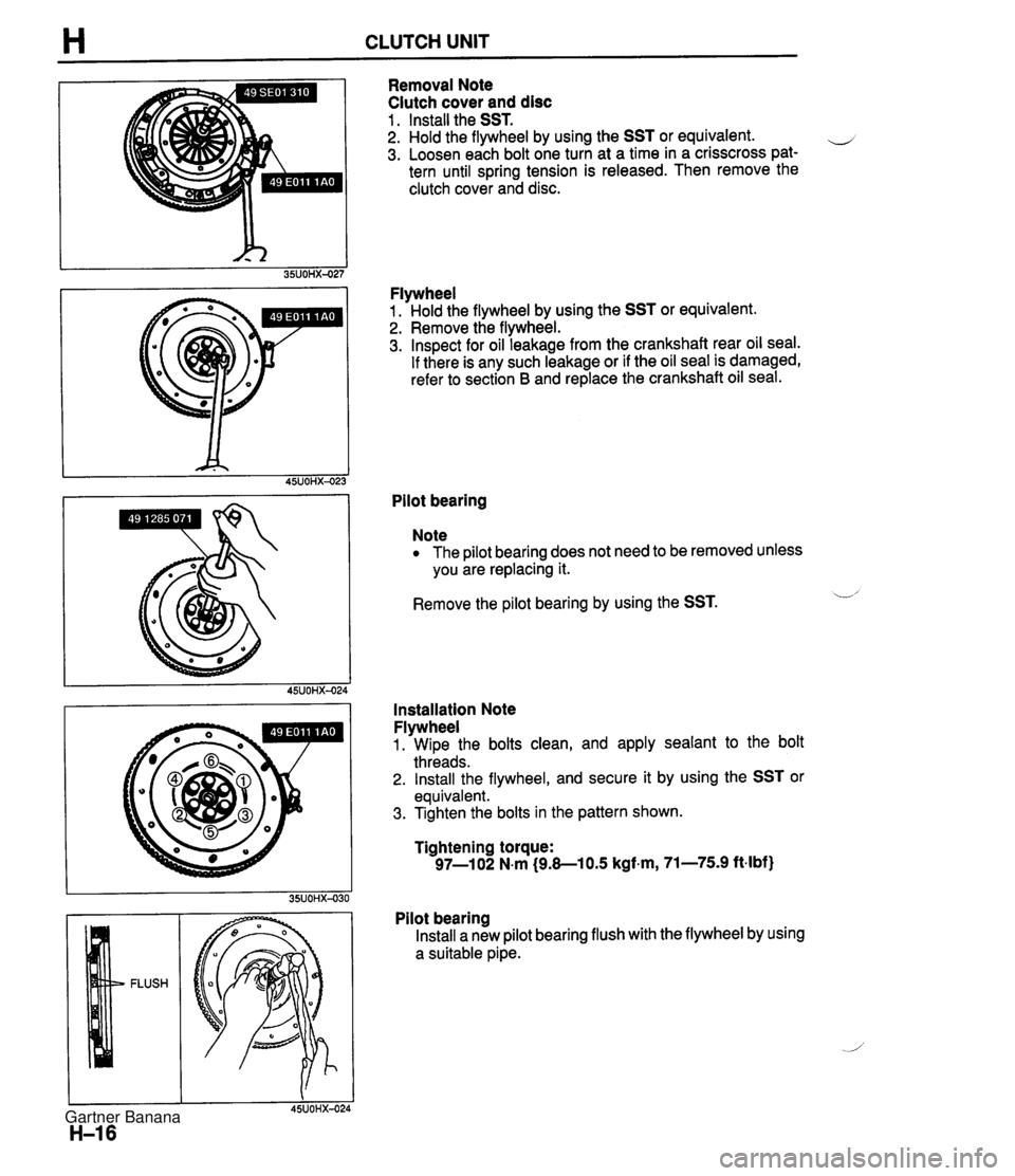
H CLUTCH UNIT Removal Note Clutch cover and disc 1 . Install the SST. 2. Hold the flywheel by using the SST or equivalent. e 3. Loosen each bolt one turn at a time in a crisscross pat- tern until spring tension is released. Then remove the clutch cover and disc. Flywheel 1. Hold the flywheel by using the SST or equivalent. 2. Remove the flywheel. 3. Inspect for oil leakage from the crankshaft rear oil seal. If there is any such leakage or if the oil seal is damaged, refer to section B and replace the crankshaft oil seal. Pilot bearing Note The pilot bearing does not need to be removed unless you are replacing it. Remove the pilot bearing by using the SST. L' Installation Note Flywheel 1. Wipe the bolts clean, and apply sealant to the bolt threads. 2. Install the flywheel, and secure it by using the SST or equivalent. 3. Tighten the bolts in the pattern shown. Tightening torque: 97-1 02 N.m (9.8-1 0.5 kgf.m, 71-75.9 ft-lbf) Pilot bearing Install a new pilot bearing flush with the flywheel by using a suitable pipe. Gartner Banana
Page 352 of 1708

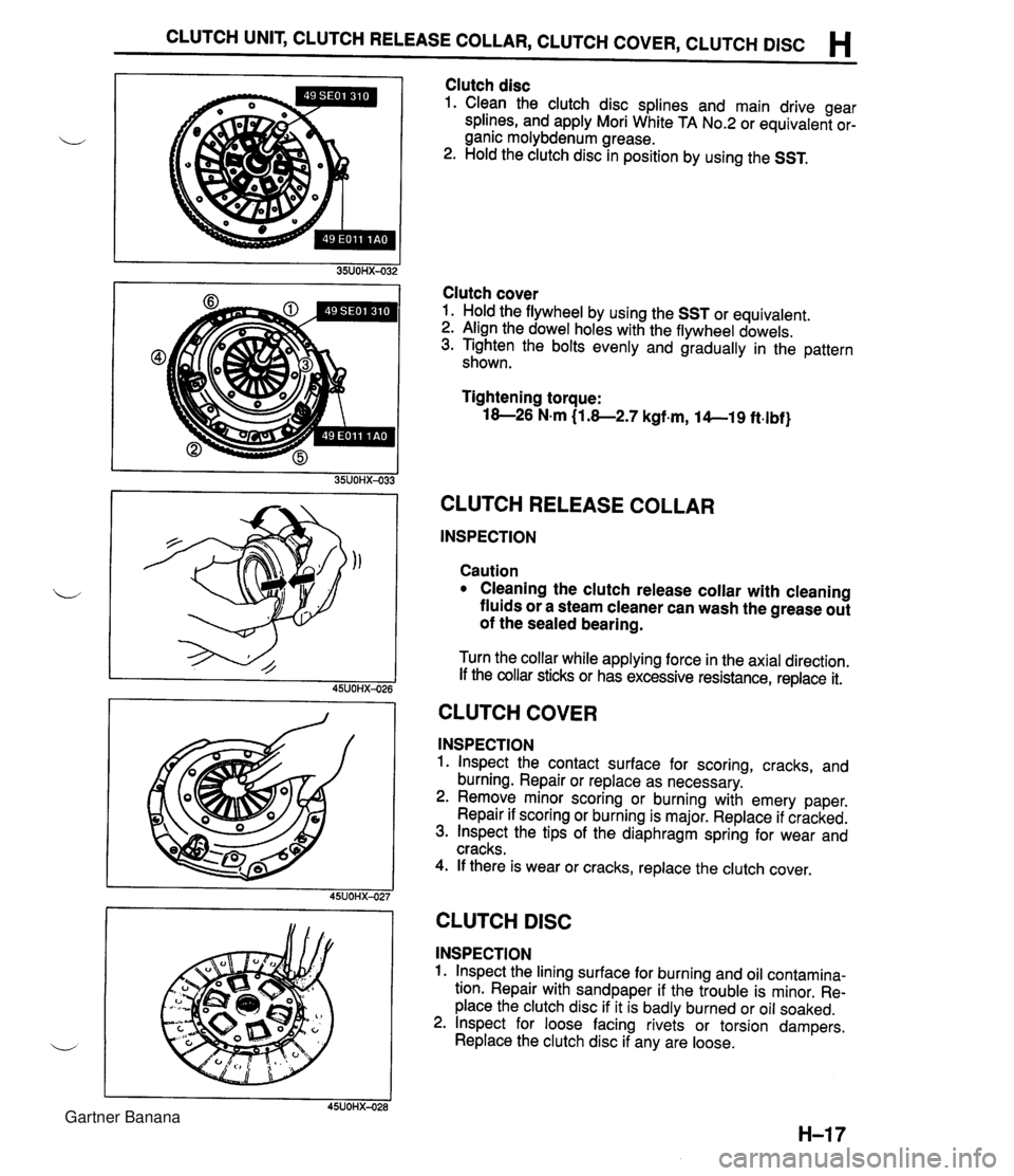
CLUTCH UNIT, CLUTCH RELEASE COLLAR, CLUTCH COVER, CLUTCH DlSC H Clutch disc 1. Clean the clutch disc splines and main drive gear splines, and apply Mori White TA No.2 or equivalent or- ganic molybdenum grease. 2. Hold the clutch disc in position by using the SST. Clutch cover 1. Hold the flywheel by using the SST or equivalent. 2. Align the dowel holes with the flywheel dowels. 3. Tighten the bolts evenly and gradually in the pattern shown. Tightening torque: 18-26 N.m (1.8-2.7 kgf.m, 14--19 ft.lbf} CLUTCH RELEASE COLLAR INSPECTION Caution Cleaning the clutch release collar with cleaning fluids or a steam cleaner can wash the grease out of the sealed bearing. Turn the collar while applying force in the axial direction. If the collar sticks or has excessive resistance, replace it. CLUTCH COVER INSPECTION 1. lnspect the contact surface for scoring, cracks, and burning. Repair or replace as necessary. 2. Remove minor scoring or burning with emery paper. Repair if scoring or burning is major. Replace if cracked. 3. lnspect the tips of the diaphragm spring for wear and cracks. 4. If there is wear or cracks, replace the clutch cover. I I 45UOHX-027 CLUTCH DlSC INSPECTION 1. lnspect the lining surface for burning and oil contamina- tion. Repair with sandpaper if the trouble is minor. Re- place the clutch disc if it is badly burned or oil soaked. 2. lnspect for loose facing rivets or torsion dampers. Replace the clutch disc if any are loose. Gartner Banana
Page 353 of 1708

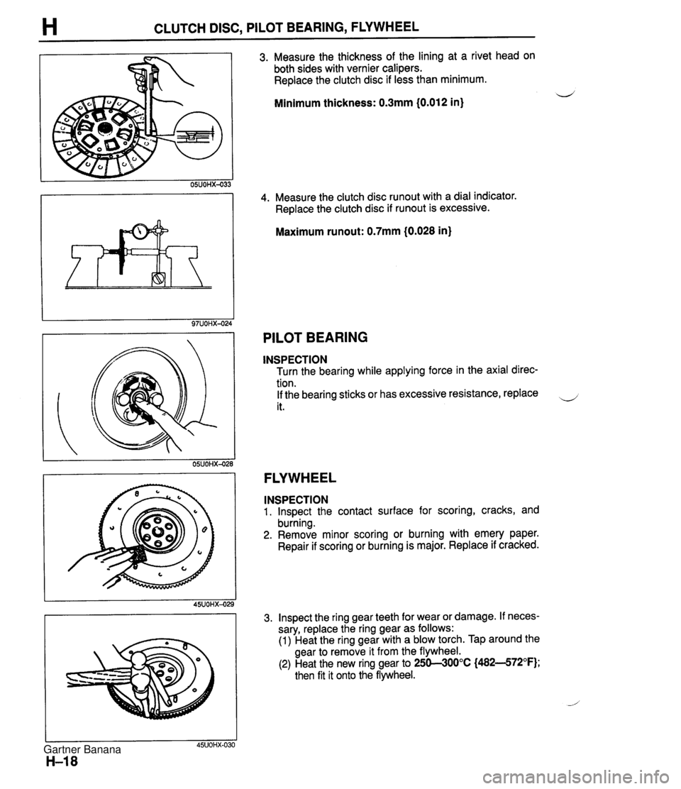
H CLUTCH DISC, PILOT BEARING, FLYWHEEL 3. Measure the thickness of the lining at a rivet head on both sides with vernier calipers. Replace the clutch disc if less than minimum. Minimum thickness: 0.3mm (0.012 in) 4. Measure the clutch disc runout with a dial indicator. Replace the clutch disc if runout is excessive. Maximum runout: 0.7mm (0.028 in) PILOT BEARING INSPECTION Turn the bearing while applying force in the axial direc- tion. If the bearing sticks or has excessive resistance, replace it. FLYWHEEL INSPECTION 1. lnspect the contact surface for scoring, cracks, and burning. 2. Remove minor scoring or burning with emery paper. Repair if scoring or burning is major. Replace if cracked. 3. lnspect the ring gear teeth for wear or damage. If neces- sary, replace the ring gear as follows: (1) Heat the ring gear with a blow torch. Tap around the gear to remove it from the flywheel. (2) Heat the new ring gear to 250--300°C (482--572°F); then fit it onto the flywheel. Gartner Banana
Page 354 of 1708
FLYWHEEL H 4. Measure the flywheel runout with a dial indicator. Replace the flywheel if runout is excessive. Maximum runout: 0.2mm (0.008 in) 9MUOHX-048 Gartner Banana
Page 409 of 1708
K TROUBLESHOOTING TROUBLESHOOTING GENERAL NOTES A problem with the EC-AT may be caused by the engine, the EC-AT powertrain, the hydraulic control LJ system, or the electronic control system. When troubleshooting, therefore, begin from these points, which can be inspected quickly and easily. The recommended troubleshooting sequence is described below. WHEEL CHOCK 63 TEMPERATURE w-7u'C (1461WF) Step 1 : On-board Diagnosis System Inspection Check for diagnostic trouble code(s) memorized in the powertrain control module (Transmission) with the Self- Diagnosis Checker. (Refer to page K-11 .) Note You can also check the flashing sequence of the hold indicator light for diagnostic trouble code(s). (Refer to page K-1 1 .) Step 2: Mechanical System Test Check the engine stall speed, time lag, and line pres- sure. (Refer to page K-22.) Step 3: Road Test Check the shift point, shift schedule, and shift shock. (Refer to page K-29.) Gartner Banana
Page 414 of 1708

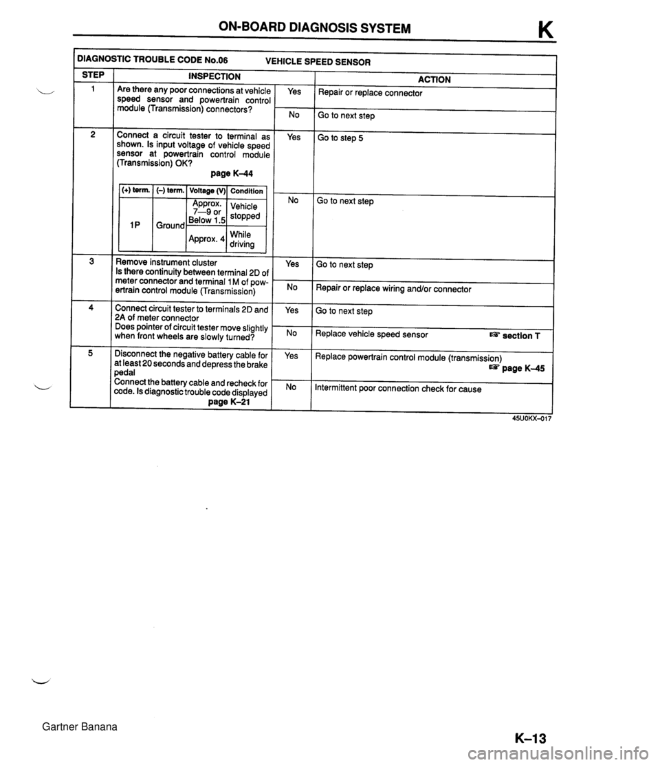
ON-BOARD DIAGNOSIS SYSTEM K )IAGNOSTIC TROUBLE CODE N0.06 VEHICLE SPEED SENSOR INSPECTION STEP ACTION Repair or replace connector Are there any poor connections at vehicle speed sensor and powertrain control module (Transmission) connectors? Yes Go to next step Connect a circuit tester to terminal as shown. Is input voltage of vehicle speed sensor at powertrain control module (Transmission) OK? page K-44 Yes Go to step 5 1 (+) term. I (-) term. ( Voltage (v)( Condition I Go to next step Below 1.5 While Remove instrument cluster Is there continuity between terminal 2D of meter connector and terminal 1 M of pow- ertrain control module (Transmission) Yes Go to next step Repair or replace wiring and/or connector Connect circuit tester to terminals 2D and 2A of meter connector Does pointer of circuit tester move slightly when front wheels are slowly turned? Yes Go to next step Replace vehicle speed sensor section T Disconnect the negative battery cable for at least 20 seconds and depress the brake pedal Connect the battery cable and recheck for code. Is diagnostic trouble code displayed Dane K-21 Yes Replace powertrain control module (transmission) page K-45 Intermittent poor connection check for cause Gartner Banana
Page 423 of 1708
K MECHANICAL SYSTEM TEST MECHANICAL SYSTEM TEST PREPARATION SST STALL TEST 49 0378 400A Gauge set, oil pressure 49 801 9 901 Gauge, oil pressure For oil pressure test For oil pressure test This test is performed to determine if there is slippage of the friction elements or malfunction of the hy- draulic components. Preparation 1. Check the engine coolant, engine oil, and ATF levels before testing. 2. Warm the engine thoroughly to raise the ATF temperature to operating level (50--80°C, 122-176°F). 3. Engage the parking brake and use wheel chocks at the front and rear of the wheels. ENGAGE PARKING BRAKE WARM UP ENGINE COOLANT LEVEL ENGINE OIL LEVEL TEMPERATURE 60-70°C (1 40-1 58°F) ATF LEVEL Gartner Banana
Page 436 of 1708
AUTOMATIC TRANSMISSION FLUID (ATF) K AUTOMATIC TRANSMISSION FLUID (ATF) ATF Inspection Level 1. Park the vehicle on level ground. 2. Apply the parking brake and position wheel chocks se- curely to prevent the vehicle from rolling. 3. Warm up the engine until the ATF reaches 60-70°C (1 40-1 58°F). 4. While depressing the brake pedal, shift the selector lever to each range (P-L), pausing momentarily in each range. 5. Shift back to P. Note In some cases it may be necessary to inspect the ATF in the cool range 15-25°C (59-77"F) before warm- ing up the engine. 6. Ensure that the ATF level is in the HOT (65°C) range. Add ATF to the specification, if necessary. ATF type: DexronQII or M-I11 Condition Determine whether the transmission should be disas- sembled by noting. 1. If the ATF is muddy or varnished. 2. If the ATF smells strange or unusual. Gartner Banana