1994 MAZDA MX-5 stop start
[x] Cancel search: stop startPage 685 of 1708

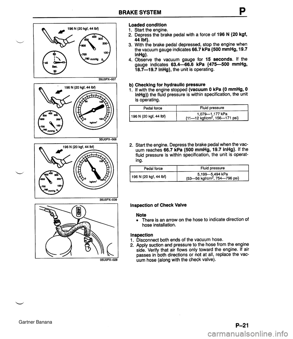
P BRAKE SYSTEM k FIRST PEDAL VACUUM GAUG DEPRESSION FORCE GAUGE POWER BRAKE UNIT Quick Inspection, On-vehicle Power brake unit function check (Simple method) ii Step 1 1. With the engine stopped, depress the pedal a few times. 2. With the pedal depressed, start the engine. 3. If immediately after the engine starts the pedal moves down slightly, the unit is operating. Step 2 1. Start the engine and let it run 1 or 2 minutes. 2. Stop the engine. 3. Depress the pedal with the usual force. 4. If the first pedal stroke is long and becomes shorter with subsequent strokes, the unit is operating. 5. If a problem is found, inspect for damage or improper connection of the check valve or vacuum hose. Repair if necessary, and inspect it once again. Step 3 1. Start the engine. 2. Depress the pedal with the usual force. 3. Stop the engine with the pedal depressed. 4. Hold the pedal down for about 30 seconds. 5. If the pedal height does not change, the unit is operating. ,, 6. If there is a problem, check for damage or improper con- nection of the check valve or vacuum hose. Repair if necessary, and check once again. If the nature of the problem is still not clear after following the 3 steps above, follow the more detailed check described in "Method using tester," below. (Method using tester) Connect the SST, vacuum gauge, and pedal depression force gauge as shown in the figure. After bleeding the air from the SST, conduct the test as described in the 3 steps below. Inspection using gauges Connect the SST gauges, a vacuum gauge (A), and a pedal depression gauge (B) as shown. Bleed the air from the SST gauges before performing the following tests. a) Checking for vacuum loss Unloaded condition 1. Start the engine. 2. Stop the engine when the vacuum gauge indicates 66.7 kPa (500 mmHg, 19.7 inHg). 3. Observe the vacuum gauge for 15 seconds. If the gauge indicates 63.4-66.6 kPa (475-500 mmHg, ,, 18.7-19.7 inHg), the unit is operating. Gartner Banana
Page 686 of 1708

BRAKE SYSTEM P (20 kgf, 44 Ibf) (20 kgf, 44 Ibf) Loaded condition 1. Start the engine. 2. Depress the brake pedal with a force of 196 N (20 kgf, 44 Ibf). 3. With the brake pedal depressed, stop the engine when the vacuum gauge indicates 66.7 kPa I500 mmHg, 19.7 inHg). 4. Observe the vacuum gauge for 15 seconds. If the gauge indicates 63.4-66.6 kPa (475--500 mmHg, 18.7-19.7 inHg), the unit is operating. b) Checking for hydraulic pressure 1. If with the engine stopped (vacuum 0 kPa (0 mmHg, 0 inHg}) the fluid pressure is within specification, the unit is operating. 1 Pedal force Fluid pressure 2. Start the engine. Depress the brake pedal when the vac- uum reaches 66.7 kPa (500 mmHg, 19.7 inHg). If the fluid pressure is within specification, the unit is operat- ing. 1 96 N {20 kgf, 44 Ibf) I Pedal force I Fluid pressure I 1,079-1,177 kPa {I 1-1 2 kgf/cm2, 156-1 71 psi) lnspection of Check Valve 196 N {20 kgf, 44 Ibf) Note There is an arrow on the hose to indicate direction of hose installation. 5,199--5,494 kPa {53-56 kgf/cm2, 754--796 psi} lnspection 1. Disconnect both ends of the vacuum hose. 2. Apply suction and pressure to the hose from the engine side. Verify that air flows only toward the engine. If air passes in both directions or not at all, replace the vac- uum hose (along with the check valve). Gartner Banana
Page 712 of 1708

ANTILOCK BRAKE SYSTEM (ABS) P N. SOLENOID TEST HAST HE WHEEL STOPPED SPINNING . AND LOCKED IN PLACE IF NO FAULTS TESlERn low THEN 1 PRESS: 0 -OR- b- I STAT TEST DYNM I I ~ESTGR WILL TESTER WILL RETURN TO SA RETURN TO 8A 41% EITHER SWITCU TO START THIS TEST (mww AWLVIM ~RM pmmmr TO MAKE CCMU IE DETECTED. I W A FAULT IS DETECTED. .AWAME TESTIRmLMIICLAYEITMR STEP. &N MEW: -on- mnw: 1 (Cont .) Gartner Banana
Page 960 of 1708

AUDIO Name ;can button 3epeat button rrack search button Press SCAN button and beginning of tunes are played one by one (10 seconds for each) Press button during playback and scanning starts from next tune Press button during scanning and tune being scanned is played Scanning is canceled automatically when all programs in disc have been scanned Illustration Press RPT button during a tune is playing to play it repeatedly Press again to cancel repeat operation and resume normal playback Operation Press button to search for beginning of next or current program 1. PressA(up) button for less than 0.5 second during disc play and be- ginning of next tune is selected and played Tunes are changed one by one with each press of button When pressed during play of last tune, first tune is replayed 2. PressV(down) button for less than 0.5 second during disc play and current tune is replayed from beginning Tunes are changed one by one with each press of button When pressed during play of first tune, last tune is replayed Press button to fast forwardheverse disc 1. Press and hold FF (up) button for more than 0.5 second and disc play position moved ahead at high speed while button pressed When last part of last tune is reached, first tune is selected and disc stops 2. Press and hold REV (down) button for opposite operation of FF button When first part of first tune reached, disc stops reversing and starts playing Clock The clock can be set while the radio or tape/CD player is ON. Illustration Clock button (clock display) HIM button (clock setup) Operation Press button to display present radio frequency or operation mode If power supply to unit is broken (burnt fuse or disconnected battery), clock setup will be canceled When clock button is pushed for 2 seconds, clock display flashes. At this point, press H button to advance hours and M button to advance minutes Press clock button again to return to normal display If clock button is pressed again while clock display is flashing and time has not been adjusted (that is, H and M buttons have not been pressed), min- utes will be set at : 00. If time before adjustment showed 30-59 minutes, time will be set at next hour For example, nn Gartner Banana
Page 963 of 1708

T AUDIO Compact disc (CD) player CD slot P Disc set light Repeat button Random-play button I Upldown button (rewindtfast forward lllustration r AUTO M SCAN J Operation Insert CD, player automatically pulls in CD and begins play Set light turns on when CD is inserted, turns off when CD is ejected Press RPT button while tune is playing to play it again after it finishes Press button again to cancel repeat operation and resume normal play Press RAN button to play tunes on disc in random order; RANDOM ap- pears on display Press again to cancel random operation and resume normal play Press SCAN button to play beginning of tunes one by one (10 seconds each) Press button during play to start scanning from next tune Press button during scanning to play current tune Scanning is canceled automatically when all programs in disc have been scanned Press button to stop play; press again to start To start CD while in radio or tape mode, press button with CD inserted in player Press button to eject CD 1. Press button for more than 1.5 seconds to rewind or fast forward; play will begin at point where button is released 2. Press button for 1.5 seconds or less to advance or reverse song selec- tion before or during play Press ( A ) button to advance to beginning of next song and begin Play Repeat procedure to advance one song at a time Press ( V) button once to return to beginning of current song Press button again to move to beginning of previous song 35UOTX-05: Gartner Banana
Page 1087 of 1708

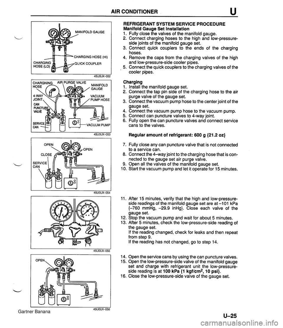
AIR CONDITIONER u NIFOLD GAUGE CHARGING HOSE (HI) QUICK COUPLER REFRIGERANT SYSTEM SERVICE PROCEDURE Manifold Gauge Set Installation 1. Fully close the valves of the manifold gauge. 2. Connect charging hoses to the high and low-pressure- side joints of the manifold gauge set. 3. Connect quick couplers to the ends of the charging hoses. 4. Remove the caps from the charging valves of the high and low-pressure-side cooler pipes. 5. Connect the quick couplers to the charging valves of the cooler pipes. Charging 1. Install the manifold gauge set. 2. Connect the tap pin side of the charging hose to the air purge valve of the gauge set. 3. Connect the vacuum pump hose to the center joint of the gauge set. 4. Connect the vacuum pump hose to the vacuum pump. 5. Connect can puncture valves to 4-way joint. 6. Fully open the can puncture valves and connect service cans to the valves. Regular amount of refrigerant: 600 g (21.2 oz) 7. Fully close any can puncture valve that is not connected to a service can. 8. Connect the 4-way joint to the charging hose that is con- nected to the gauge set air purge valve. 9. Open all the valves of the manifold gauge set. 10. Start the vacuum pump and let it operate for 15 minutes. 11'. After 15 minutes, verify that the high and low-pressure- side readings of the manifold gauge set are at -1 01 kPa {-760 mmHg, -29.9 inHg}. Close each valve of the gauge set. 12. Stop the vacuum pump and wait for about 5 minutes. 13. After 5 minutes, check the low-pressure-side reading of the gauge set. If the reading changed, check for leaks and then repeat from step 9. If the reading has not changed, go to step 14. 14. Open the service cans by using the can puncture valves. 15. Open the low-pressure-side valve of the manifold gauge set and charge with refrigerant unit the low-pressure- side reading is at 100 kPa (1 kgf/cm2, 10 psi). 16. Close the low-pressure-side valve of the gauge set. Gartner Banana
Page 1089 of 1708

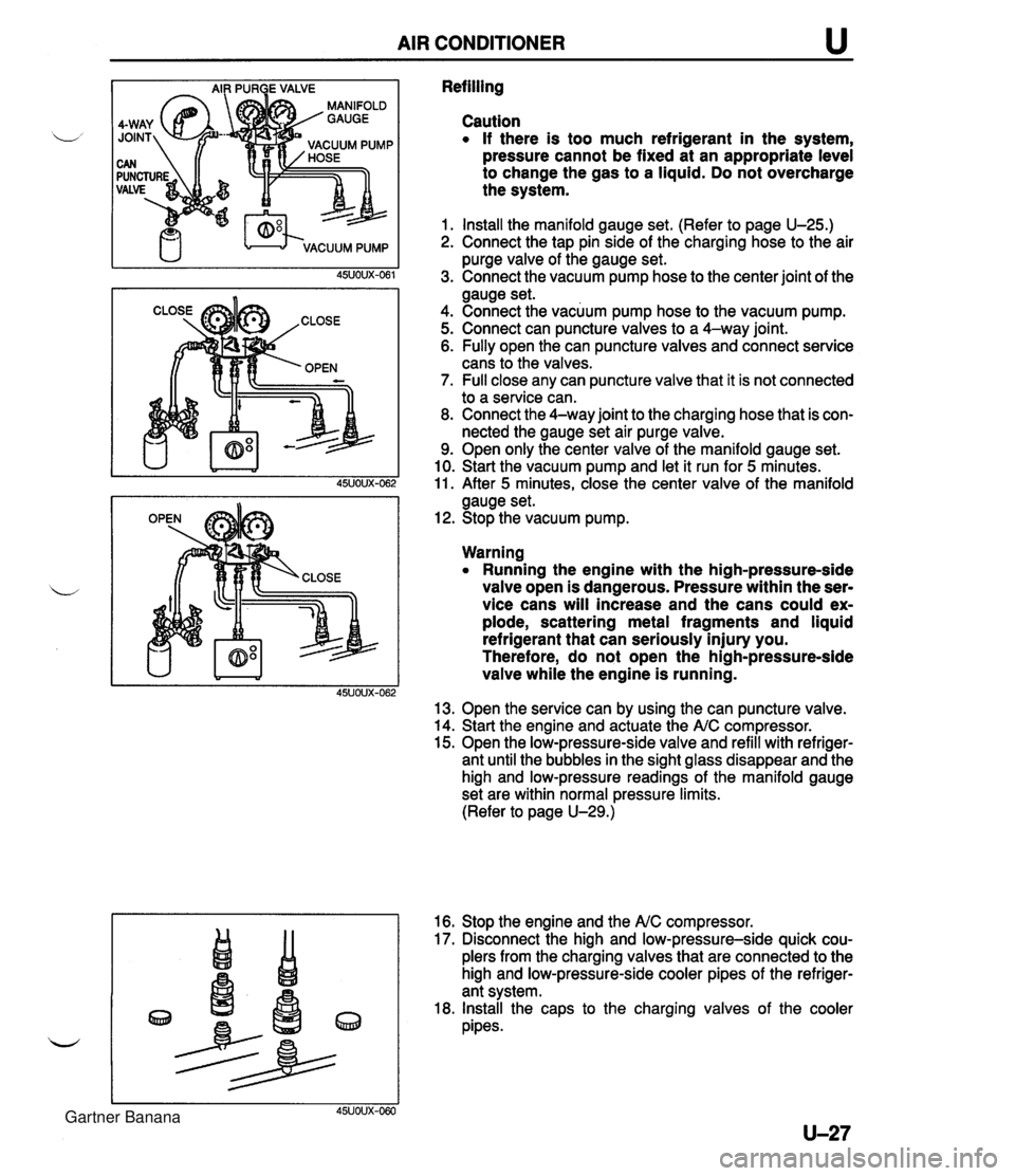
AIR CONDITIONER u Refilling Caution If there is too much refrigerant in the system, pressure cannot be fixed at an appropriate level to change the gas to a liquid. Do not overcharge the system. 1. Install the manifold gauge set. (Refer to page U-25.) 2. Connect the tap pin side of the charging hose to the air purge valve of the gauge set. 3. Connect the vacuum pump hose to the center joint of the gauge set. 4. Connect the vacuum pump hose to the vacuum pump. 5. Connect can puncture valves to a 4-way joint. 6. Fully open the can puncture valves and connect service cans to the valves. 7. Full close any can puncture valve that it is not connected to a service can. 8. Connect the 4-way joint to the charging hose that is con- nected the gauge set air purge valve. 9. Open only the center valve of the manifold gauge set. 10. Start the vacuum pump and let it run for 5 minutes. 11. After 5 minutes, close the center valve of the manifold gauge set. 12. Stop the vacuum pump. Warning Running the engine with the high-pressure-side valve open is dangerous. Pressure within the ser- vice cans will increase and the cans could ex- plode, scattering metal fragments and liquid refrigerant that can seriously injury you. Therefore, do not open the high-pressure-side valve while the engine is running. 13. Open the service can by using the can puncture valve. 14. Start the engine and actuate the A/C compressor. 15. Open the low-pressure-side valve and refill with refriger- ant until the bubbles in the sight glass disappear and the high and low-pressure readings of the manifold gauge set are within normal pressure limits. (Refer to page U-29.) 16. Stop the engine and the NC compressor. 17. Disconnect the high and low-pressure-side quick cou- plers from the charging valves that are connected to the high and low-pressure-side cooler pipes of the refriger- ant system. 18. Install the caps to the charging valves of the cooler pipes. 45UOUX-060 Gartner Banana
Page 1697 of 1708

ALPHABETICAL INDEX *a* ENGLISH S** - BELTtA1(L) ,FRT BELt'A1(R),FRT SEAT------ BOLT,JACK SET------------ BELTtB'(R),FRT SEAT------ BOLT,LAMP LID------------ BELTIB1,FRT SEAT--------- BELTlVl------------------ 1-05 2-KB BKACKETJCOUPLER-KNOCK SEN BHACKET,CRASH PAD-------- BRACK~T,E~G.K.PIPE------- BRACKET,FENDER----------- *********Y******* * * * A * * * **#*~******%***** ACTUATOR,A.C.C.---------- 2-Jl3 ACTUATOR, SHIFT LOCK---- -- 1-616 ADAPTERIDRIVE PLATE------ 1-J7 ADJUSTER NO .J-----.----- -- 2-M8 ADJUSTER N0.4------------ 2-M8 AGJUSTER,HYDRAULIC LASH-- 1-N3 ADJUSTER,NO.1------------ 2- J8 ADJUSTER,N0.2------------ ALTERNATOR--------------- 2-J8 1-C7 ANCHOR UNIT(L),BE?T------ 2-39 ANCHOR UNIT(R1,BELT------ 2-D9 ANTENNA,RADI3------------ 2-~141 ANTILOCK BRAKE----------- 1-N15 ARM NO.1, LINK------------ 2-H15 ARM N0.2,LINK------------ 2-115 ARM(L1,LOWER------------- 1-113 ARM(L),LOWER-REAR-------- 1-F12 ARM(L1,UPPER------------- 1 -H13 ARM(R),l.OWER------------- 1-H13 ARM(R),LOWER-REAR-------- 1-F121 ARM(R),UPPER------------- 1-H13 ARM,UPPFR-FRT------------ 1 -HI31 ARM.UPPER-REAR----------- 1-F121 - 1-~6 BEZEL(L1,HEAD LAMP------- 2-M3 BEZEL!"),HEAD LAMP------- 2 -M3 BLADE(d>,WIPER-FRONT----- 2-H15 BLADE WIPER-FRONT--------- 2-H15 BLOCK,CYLINDER----------- BLOCKIFUSE--------------- 1 -H3 2-614 BLOCK,MAIN FUSE---------- BLOWER UNIT-----.-------- 2-114 2-Fll BODY 8 PISTON(L),CALIPER- 1-F11 > -fit v BUSHlNG,RUBBER-LOWER ARM- A-LTAJ BODY & PISTON(R),CALIPER- 1-FS1 1-613 BODY(L),FRONT DOOR------- 2- J9 BODY(R),FRONT DOOR------- 2-J9 BODY,CONTROL VALVE-UP---- 1 -GB BODY,LOW-RADIO ANTENNA--- 2-El4 BODY,THROTTLE------------ 1 -K4 BODY.VALVE LWR----------- 1 -18 BRACKET,MEMBER----------- 2-J7 BRACKET.PARKING CABLE-FLO 2-K5 i-Miii SRACKET~STARTER----------- 1-~6 BRACKETISTOPPER-3kTTERY-- 1-i7 BRACKET,VANE PUMP-------- 1-C13 BRACKET, WASHER TANK ------ 2-C15 2-F15 BRACKET,WIRE CLIP-OXYGEN- 1-F3 BRACKET,WIRING----------- 2-H14 BREATHER---.-------------- 2-114 1-ti11 1 -L7 1-111 BRE/tTHER,AIR-T/MISSION--- 1-D6 BRKT(!i,BUMPER-RR SKIRT-- 2-L5 BdKT(L1,SEAT-F.FLOOR PAN- 2-L5 BRKT(L),TRK.BOARD-FENDER- 2-J5 BRKT(R),BUNPER-RR SKIRT-- 2-L5 BF!KT(R) ,SEAT-F. FLOOR PAN- 2-K5 BRKT,AIR CLNR-WHL APRON-- 2-C5 BRKT,BATT.CLANP-QTR PANEL 2-05 BRKT ,CAP-QUARTER PANEL--- 2- I5 BRKT,DIAGNOSlS UNIT------ 2-H13 BRKT,DIAGNOSIS/POWER UNIT 2-H13 BRKT,MOTOR-ANTENNA------- 2-El4 BRKTtA1,WASHER TANK-FRT-- 2-El5 BRUSH-.------------------- 1 -C7 1 -F7 BRUSH ,YOKE-- - - - - - --- - - - - -. 1-F7 BuLa--------------------- 1 -H7 2-C4 2-C7 2-D4 2-F.4 2-67 2-H4 2 -H7 2 - L 7 BULn 8 SOCKET------------ 2-L7 BUL0,MODE CONTROL-------- 2-El 1 BULB,RESISTOR------------ 2-C7 2-67 BULB'Bt,SWITCH-RR DEFOGER 2-El3 BUMPER, FRONT - --- - . -- -. .. - - BUMPER, REAR- - - - - - - - - - - - - - 2 - E3 2-H3 BUSH---------.----------- 1-1115 1-616 1 - r; 1 tl 1 - .I6 1 -Ll4 - .-.- - L A1 BRACKET------------------ 1 -LIB 1-K7 1-1.15 2-C15 2-G14 2-H141 2-L5 BRACKET NO 1,k.B.S.------ 1 -MI 5' BRACKET ~0.5,A.B.S.------ 1 -M! 5 BRACKET(L),CABLE--------- 1-GI1 BRACKET(L1,ENGINE-------- BRACKET(L),F. BUMPER SIDE 2-F3 BRACKET(L),FRONT-AUDIO--- BRACKETCL) ,HINGE-LAPP LID 2-M3 BRACKETfL),IHST.--------- 2-F5 BRACKET(L1,TUNER--------- BRACKET(L),RADTATOR------ 2-N4 BRACKET(L),STARILIZER---- 2-D5 2-N13 RRACKET(R),CABLE---------- 1 -Gll NRACKET(R),ENGINE-------- i l-cl41 BRACKET(P),FRONT-AUDIO--- BRACKET(R),HIHGE-LAMP LID 2-M3 IRAcKET(R),INsT.--------- 2-M131 2-F5 BRACKET(R1,RADIATOR------ 2-N4 I BRACVET(R),STARILIZER---- 2-C5 I bRACKET(R) ,TUNER--------- 2-N13 BRACKET(RR),AUDIO-------- 2-N131 BRACKET,ACCEL WIRE------- 1-04 BRACKET ,ACTUATOR--- - ----- 2-~131 BRACKET,ACTUATOR-P.C.C.-- 2-313 RRACKET,ACTUATUR-FRONT--- 2-J13 RRACKET,AIR CLEPAER------ 1-14 1 BRACKET,BATTERY CLAMP---- 1-17 BKACKET,BUHPER---- ------- 2-N4 I BRACKET,CAHISTER-- .--- .. - 1-F4 BRACKET,CLAMP------------ 2-1111 BRACKET ,CLIP ------ 2 - L 3 BRACKET,COMPRESSOR------- 1-65 1 BRACKE1,CONTROL UNIT- .--- 1-Cl5 2-C13' BRACKET,COUPLER----- ----- 1-1112' ... - - .- - --.A- €-001 BACK(L1,FRONT SEAT------- 2-C9 I BACK(R),FRONT SEAT----- -- 2-1 A BAG,TOOL----------------- 2-MB / 2-Dl6 BALL JOINT,LOWER--------- BALL, S'TEEL - - - - - - - - - - - - - - - 1-113 1-El4 1 -H7 BAUD--------------------- 1-Dl41 CAP SET,KESERVE TANK----- 1 -I 131 BOLT,AIR CLEANER--------- 1-14 BOLT,AIR C0K.------------ 2-Jll BOLT,ANCHOR END---------- 1.M7 BOLT,BAFFLE PLATE-------- 1 -K7 dOLT,BEARING CAP--------- 1 -H3 BOLT,CAMSHAFT CAP-------- 1-E3 BOLT,CARRIER------------- 1 -K11 ~OLT,CL&MP--------------. 1-14111 1-17 BOLT .COMPRESSOR---------- 2-1111 BOLT,COEPRESSOR-AIR CON.- 2-Kll BOLT,CONNECTOR----------- 1-~151 1-615 BEARlNG,BALL------------- 1-66 ! BFARING.BALL-ALT. FRONT- - 1 -C7 I BEARING~BALL-ALT. REAR--- 1-ci I REARING, BALL-COUNTER SHAF 1 -G6 I BEARING~BALL-FLY WHEEL--- BEARING,RALL-MAIN DRIVE G BEARING,BALL-MAI!i SHAFT-- BEARING,IIEEDLE----------- CA?,TOP LOCK---------.--- CAP,VANE PUMP TANK------- CARRIER,DlFFERENTIAL----- BOLT ]CONTROL VALVE------- 1-C8 I 1 -E8 1-KB I !!7LT,CROSS MEMBER-------- 2-C5 I BOL1,CYLINDER HEAD------- 1-E3 ' BOLT.UECK LOCK----------- 2-112' 1-LIZ; BEAR1NCi.WtiEEL--------- ---- 1-El11 BELT TIMING------ 1-NJ ! .. . CAT . AUNAOS - U3 Gartner Banana