Page 877 of 1708

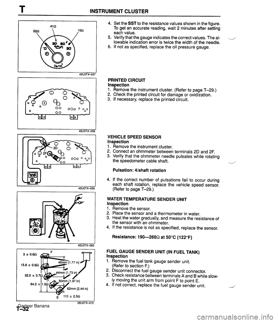
T INSTRUMENT CLUSTER 4. Set the SST to the resistance values shown in the figure. To get an accurate reading, wait 2 minutes after setting each value. 5. Verify that the gauge indicates the correct values. The al- \J lowable indication error is twice the width of the needle. 6. If not as specified, replace the oil pressure gauge. PRINTED CIRCUIT lnspection 1. Remove the instrument cluster. (Refer to page T-29.) 2. Check the printed circuit for damage or oxidization. 3. If necessary, replace the printed circuit. VEHICLE SPEED SENSOR lnspection 1. Remove the instrument cluster. 2. Connect an ohmmeter between terminals 2D and 2F. 3. Verify that the ohmmeter needle pulsates while rotating the speedometer cable shaft. ~ Pulsation: Ushaft rotation 4. If the correct number of pulsations fail to occur during each shaft rotation, replace the vehicle speed sensor. (Refer to page T-29.) WATER TEMPERATURE SENDER UNlT lnspection 1. Remove the sensor. 2. Place the sensor and a thermometer in water. 3. Heat the water gradually, and measure the resistance of the sensor with an ohmmeter. 4. If the resistance is not as specified, replace the sensor. Resistance: 190-260Q at 50°C (1 22°F) FUEL GAUGE SENDER UNlT (IN FUEL TANK) lnspection 1. Remove the fuel tank gauge sender unit. (Refer to section F.) 2. Disconnect the fuel gauge sender unit connector. 3. Check resistance between terminals A and B while slow- ly moving the unit arm from point F to point E. 4. If not correct, replace the fuel gauge sender unit. 2 Gartner Banana
Page 1094 of 1708

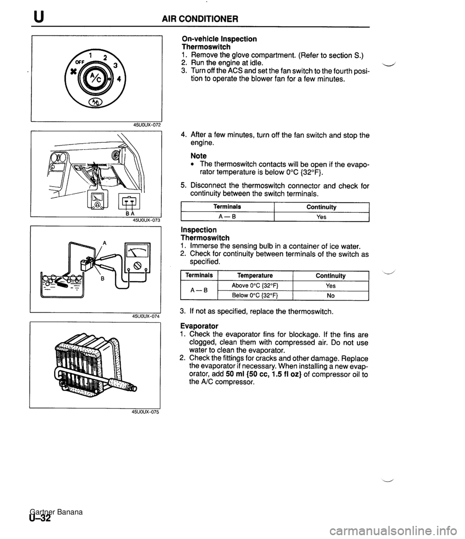
AIR CONDITIONER On-vehicle Inspection Thermoswitch 1. Remove the glove compartment. (Refer to section S.) 2. Run the engine at idle. u 3. Turn off the ACS and set the fan switch to the fourth posi- tion to operate the blower fan for a few minutes. 4. After a few minutes, turn off the fan switch and stop the engine. Note The thermoswitch contacts will be open if the evapo- rator temperature is below 0°C (32°F). 5. Disconnect the thermoswitch connector and check for continuity between the switch terminals. I Terminals I Continuity I I A-B I Yes I - -- Inspection Thermoswitch 1. Immerse the sensing bulb in a container of ice water. 2. Check for continuity between terminals of the switch as specified. 3. If not as specified, replace the thermoswitch. Continuity ( Terminals I Temperature A-B Evaporator 1. Check the evaporator fins for blockage. If the fins are clogged, clean them with compressed air. Do not use water to clean the evaporator. 2. Check the fittings for cracks and other damage. Replace the evaporator if necessary. When installing a new evap- orator, add 50 ml (50 cc, 1.5 fl oz) of compressor oil to the A/C compressor. d Above 0°C {32OFj Below 0°C (32°F) Yes No Gartner Banana
Page 1113 of 1708

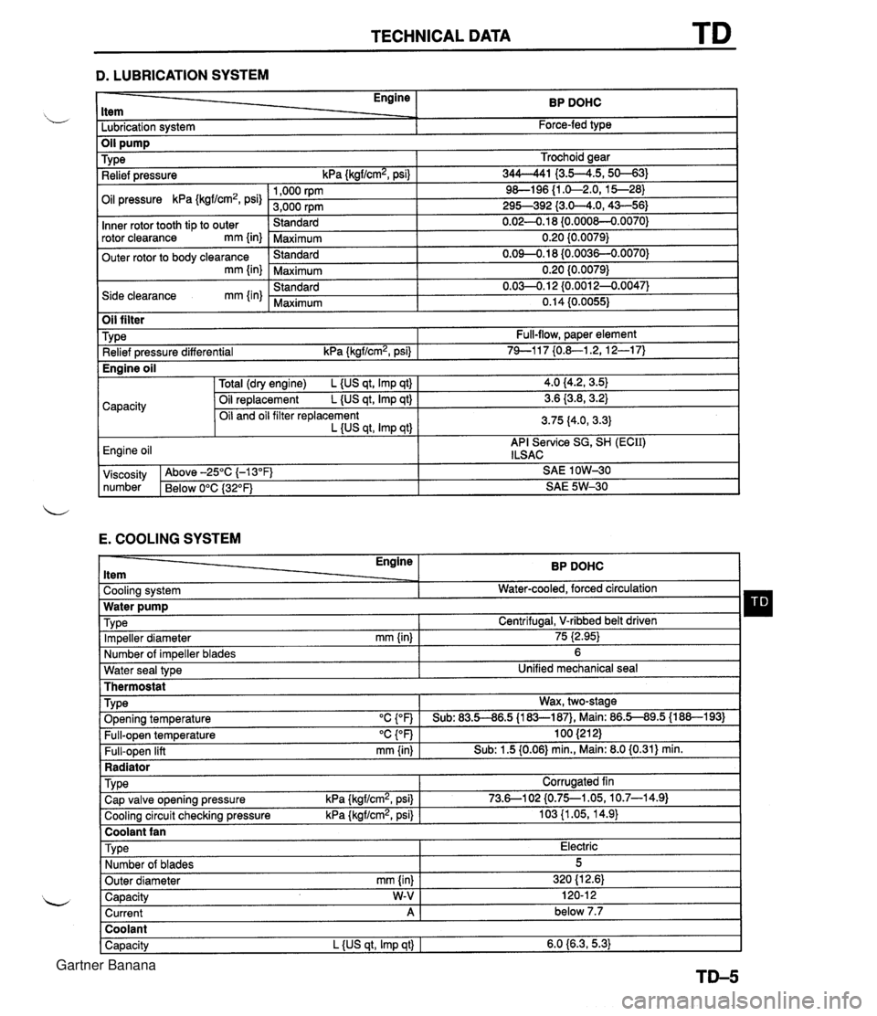
TECHNICAL DATA D. LUBRICATION SYSTEM - Engine ltem BP DOHC - -. Lubrication system Force-fed type E. COOLING SYSTEM Trochoid gear 344-41 I3.5--4.5,s-31 9&l96 {I .&2.0, 15--28) 295-392 {3.0-4.0,43-56) 0.02-0.1 8 {0.000&0.0070) 0.20 {0.0079) 0.09-0.18 (0.0036-0.0070) 0.20 {0.0079) 0.03-0.1 2 {0.0012-0.0047) 0.14 (0.0055) TY pe Relief pressure kPa {kgf/cm2, psi) Oil pressure kPa {kgf/cm2, psi) Inner rotor tooth tip to outer rotor clearance mm {in) Outer rotor to body clearance mm {in) Side clearance mm {in) Water seal type I Unified mechanical seal Thermostat 1,000 rpm 3,000 rpm Standard Maximum Standard Maximum Standard Maximum Oil filter Engine ltem - - Cooling system . . Impeller diameter mm {in) Number of impeller blades Type Relief pressure differential kPa {kgf/cm2, psi) BP DOHC Water-cooled, forced circulation - 75 i2.95) 6 Full-flow, paper element 74-1 17 {0.&1.2, 12-1 7) TY pe . ., . . . - Radiator I Water pump Wax, two-stage v. . . Full-open temperature "c {OF) Full-open lift mm {in) Engine oil TVD~ O~enina tem~erature "C con I Sub: 83.5-86.5 U83-187). Main: 86.5-89.5 (1 88-1 931 100 (21 2) Sub: 1.5 (0.06) min., Main: 8.0 (0.31) min. -. . - . . Cooling circuit checking pressure kPa {kgflcmz, psi) I 103 {I .05, 14.9) I Centrifugal, V-ribbed belt driven TY pe I Coolant fan I 4.0 (4.2, 3.5) 3.6 {3.8,3.2) 3.75 (4.0, 3.3) API Service SG, SH (ECII) ILSAC Capacity Corrugated fin viscosity Above -25°C (-1 3°F) SAE 1 OW-30 number Below 0°C {3Z°F) SAE 5W-30 Total (dry engine) L {US qt, Imp qt) Oil replacement L {US qt, Imp qt) Oil and oil filter replacement L {US qt, Imp qtl Cap valve o~enina pressure kPa {krrf/cm2, psi} 1 73.6--102 {0.75--1.05, 10.7-14.91 Capacity W-V I 120-1 2 Current A 1 below 7.7 Engine oil Type Number of blades Outer diameter mm {in) Coolant Capacity L {US qt, Imp qt) I 6.0 {6.3,5.3) Electric 5 320 (1 2.61 Gartner Banana
Page 1114 of 1708
![MAZDA MX-5 1994 Workshop Manual TD TECHNICAL DATA Idle speed rpm 1 800-900 (850 2 50) [MT], 750-850 (800 f 50) [ATJ lanition timina BTDC I 9"-11 (10 f 1") u F. FUEL AND EMISSION CONTROL SYSTEMS - Engine ltem Item 1 Throat diam MAZDA MX-5 1994 Workshop Manual TD TECHNICAL DATA Idle speed rpm 1 800-900 (850 2 50) [MT], 750-850 (800 f 50) [ATJ lanition timina BTDC I 9"-11 (10 f 1") u F. FUEL AND EMISSION CONTROL SYSTEMS - Engine ltem Item 1 Throat diam](/manual-img/28/57072/w960_57072-1113.png)
TD TECHNICAL DATA Idle speed rpm 1 800-900 (850 2 50) [MT]', 750-850 (800 f 50) [ATJ' lanition timina BTDC I 9"-11' (10' f 1")' u' F. FUEL AND EMISSION CONTROL SYSTEMS - Engine ltem Item 1 Throat diameter mm {in) 1 55 (2.2) 1 Antifreeze solution BP DOHC Specification 1 Throttle body Fuel pump TY pe I Impeller (in-tank) Coolant protection Above -1 6°C (3°F) Above -26°C (-15°F) Above -40°C {-40°n Tv~e -. Output pressure kPa (kgf/cm2, psi) I 294-437 {3.0--6.5,43--92) Fuel filter Specific gravity at 20°C {WF) 1.054 1.066 1.078 Volume percentage % Horizontal draft Water 65 55 45 -. . - Regulating pressure kPa {kgf/cm2, psi) I 280-289 I2.85--2.95, 40.141.9) Fuel iniector Coolant 35 45 55 TY pe IAC valve Solenoid resistance n 1 10.7-1 2.3 (at 20°C (68°F)) Low-pressure side TYP~ Type of drive Resistance n Purge solenoid valve Solenoid resistance n 1 23-27 (at 20°C (68°F)) I Nylon element Pressure regulator TY pe High-ohmic Voltage 13.8 (at 20°C (68"FI) Engine coolant temperature sensor 7 20°C {68"F) I 2.21 -2.69 Resistance kn I 80°C (1 76OF} I 0.287-0.349 High-pressure side Diaphragm i/ Crankshaft position sensor Air valve Openin~l temperature OC {OF) I Below 45 (1 131 Paper element Twe 1 Fuel tank I Hall effect . . . . . . . Capacity L {US gal, Imp gal) I 48 {12.7, 10.5) Air cleaner housing Element type Free play mm (in) I 1-3 {0.039--0.118) I Fuel Oil permeated Specification Accelerator cable Unleaded regular (RON 87 or higher) J +....with system selector (49 B019 9AO) test switch at SELF TEST Gartner Banana
Page 1323 of 1708
![MAZDA MX-5 1994 Workshop Manual UNDERCOATING, PVC PAINTING AND RUST PREVENTIVE WAX TREATMENT Air dry a minimum of 4-6 hours [20°C (68OF)l. L Heat dry a minimum of 30-40 minutes [60°C (140°F)]. Color coat i Apply coating afte MAZDA MX-5 1994 Workshop Manual UNDERCOATING, PVC PAINTING AND RUST PREVENTIVE WAX TREATMENT Air dry a minimum of 4-6 hours [20°C (68OF)l. L Heat dry a minimum of 30-40 minutes [60°C (140°F)]. Color coat i Apply coating afte](/manual-img/28/57072/w960_57072-1322.png)
UNDERCOATING, PVC PAINTING AND RUST PREVENTIVE WAX TREATMENT Air dry a minimum of 4-6 hours [20°C (68OF)l. L Heat dry a minimum of 30-40 minutes [60°C (140°F)]. Color coat i Apply coating after PVC paint film is thoroughly dry. Sanding is not necessary if all oil and grease were completely removed. Conditions such as air pressure, paint viscosity, etc. can be same as for ordinary body coating. -1 Done in same way as for ordinary body coating. Nozzle type A Nozzle type B RUST PREVENTIVE WAX TREATMENT WAX APPLICATION PROCEDURE Preparation of equipment 1. Prepare equipment suitable for the wax chosen. 2. Use the correct nozzle, spray pattern, and in- jection pressure based on instructions provided for the wax. 3. If necessary, clean the nozzle with thinner before beginning work. Preparation of vehicle (or parts) 1. Scrape mud, etc. off the wax application area. 2. Dry any water collected at the wax application area. 3. The temperature of the vehicle body should be kept at more than 10°C (50°F) during the opera- tion. 4. Close all windows of the vehicle. Caution When repairing a damaged part, complete painting first, then apply the wax. The reasons are: a) The wax is sometimes dissolved by heat [more than 120°C (248OF)I during the drying process, resulting in deteriorated anticor- rosion effects. b)lf the wax applied before painting is smeared over the paint application surface, poor painting will result because the wax repels the paint. Gartner Banana
Page:
< prev 1-8 9-16 17-24