Page 130 of 1708
OIL COOLER D OIL COOLER REMOVAL I INSTALLATION 1. Disconnect the negative battery cable. 2. Drain the engine oil and engine coolant. (Refer to page D-5, Section E.) 3. Remove in the order shown in the figure. 4. Install in the reverse order of removal. INSTALL OIL COOLER WITH IDENTIFICATION MARK (BLACK) FACING UP A OIL FILTER^ RUBBER I 3049 (3.0--4.0,22-28) REPLACE Nm {kgtm, ft4bf) 1. Oil filter 3. Oil cooler Replacement . . . . . . . . . . . . . . . Page D-6 4. O-ring 2. Water hose Steps After Installation 1. Connect the negative battery cable. 2. Fill with the specified amount and type of engine oil and engine coolant. (Refer to page D-5, Section E.) 3. Start the engine and check for leaks. 4. Check the oil level and add oil if necessary. 5. Recheck the engine coolant levels. Gartner Banana
Page 157 of 1708

F OUTLINE SPECIFICATIONS Item Specification I Throttle body Throat diameter mm {in) I 55 I2.2) Idle speed rpm Ignition timing BTDC 800-900 (850 -+ 50)[MIb, 750-850 (800 + 50)[ATJe 9"-11" (10" k 1 ")* ~ut~~~ressure kPa {kgf/cm2, psi) 1 46-57 14.9--6.7,6%95) Fuel filter Fuel pump TY pe -- m&e regulator Impeller (in-tank) Low-pressure side Hi~h-pressure side Nylon element Paper element Fuel injector TY pe I High-ohmic Type Regulating pressure kPa {kgf/cm2, psi) Diaphragm 26S314 (2.7--3.2,38--46) ldle Air Control Valve Solenoid resistance n 1 10.7-1 2.3 (at 20°C {M°F)) Type of drive Resistance R Voltage 12-1 6 (at 20°C {68"F)) I Solenoid resistance 1 23-27 (at 20°C (68"FJ) I -- brankshaft position sensor d Air valve Opening temperature I Resistance Below 40°C {I 04°F) TY pe Capacity L {US gal, Imp gal) I 48 {12.7, 10.5) Air cleaner housing Purae solenoid valve Hall effect Engine coolant temperature sensor Free play mm (in) I 1-3 {0.0394.118) Fuel Specification 1 Unleaded regular (RON 87 or higher) Element type I I -. I *... With System Selector (49 B019 9AO) test switch at SELF TEST. 35UOFX-004 Oil permeated Accelerator cable Gartner Banana
Page 158 of 1708

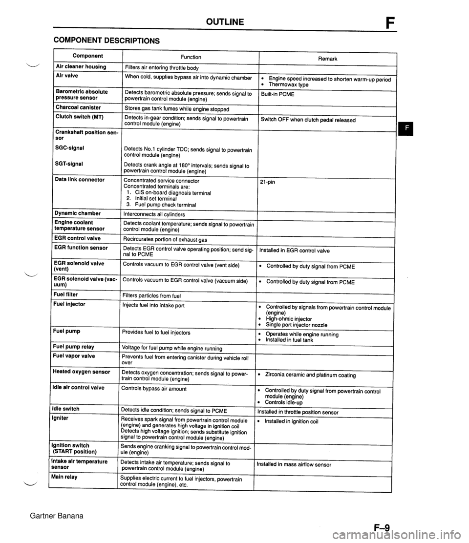
OUTLINE F COMPONENT DESCRIPTIONS Component Air cleaner housing Air valve Remark Function Filters air entering throttle body When cold, supplies bypass air into dynamicchamber w Engine speed increased to shorten warm-up period Thermowax type Barometric absolute pressure sensor Detects barometric absolute pressure; sends signal to powertrain control module (engine) 3uilt-in PCME Charcoal canister Clutch switch (MT) Stores gas tank fumes while engine stopped Detects in-gear condition: sends signal to powertrain control module (engine) --- ~witch OFF when clutch pedal released Crankshaft position sen- sor Detects No.1 cylinder TDC; sends signal to powertrain control module (engine) Detects crank angle at 180" intervals; sends signal to powertrain control module (engine) Data link connector Concentrated service connector Concentrated terminals are: 1. CIS on-board diagnosis terminal 2. Initial set terminal 3. Fuel pump check terminal Dynamic chamber Interconnects all cylinders Detects coolant temperature; sends signal to powertrain control module (engine) Recircurates oortion of exhaust aas Engine coolant temperature sensor EGR control valve lnstalled in EGR control valve EGR function sensor Detects EGR control valve operating position; send sig- nal to PCME EGR solenoid valve (vent) Controls vacuum to EGR control valve (vent side) Controlled by duty signal from PCME . - EGR solenoid valve (vac- Controls vacuum to EGR control valve (vacuum side) 0 Controlled by duty signal from PCME uum) Fuel filter Filters particles from fuel Injects fuel into intake port Fuel injector Controlled by signals from powertrain control module (engine) High-ohmic injector 0 Sinale port injector nozzle Fuel pump Provides fuel to fuel injectors 0 operates while engine running lnstalled in fuel tank Fuel pump relay Voltage for fuel pump while engine running Fuel vapor valve Prevents fuel from entering canister during vehicle roll over Heated oxygen sensor Detects oxygen concentration; sends signal to power- train control module (engine) 0 Zirconia ceramic and platinum coating ldle air control valve Controls bypass air amount Controlled by duty signal from powertrain control module (engine) Controls idle-up lnstalled in throttle position sensor lnstalled in ignition coil ldle switch Igniter Detects idle condition; sends signal to PCME Receives spark signal from powertrain control module (engine) and generates high voltage in ignition coil Detects high voltage ignition; sends substitute ignition signal to powertrain control module (engine) Ignition switch (START position) Sends engine cranking signal to powertrain control mod- ule (engine) Intake air temperature sensor Detects intake air temperature: sends signal to powertrain control module (engine) Installed in mass airflow sensor Main relay Supplies electric current to fuel injectors, powertrain control module (engine), etc. Gartner Banana
Page 225 of 1708

ENGINE TUNE-UP - TIMING LIGHT - 45UOFX422 GND Irnr Air Cleaner Element Inspection 1. Check the air cleaner element for excessive dirt and for oil and damage. Caution Cleaning the element with compressed air will re- duce the element's ability to filter the air. Don't use compressed air to clean the element. 2. Replace the element if necessary. ADJUSTMENT Preparation 1. Warm up the engine to normal operating temperature. 2. Turn all electric loads OFF. Headlight switch Blower switch Rear window defroster switch 3. Connect the SST to the data link connector. 4. Connect a timing light to the engine. 5. Connect a tachometer to the data link connector terminal IG- as shown. Ignition Timing 1. Perform Preparation. (Refer to above.) 2. Verify that the idle speed is within the specification; if not, adjust it. Idle speed 4 (Neutral): 800-900 (850 + 50) rpm [MT] (P range): 750-850 (800 & 50) rpm [AT] 3. Set switch A to position 1. 4. Set test switch to SELF TEST. 5. If the SST is not used, connect a jumper wire between the TEN terminal and the GND terminal of the data link connector. 6. Verify that the idle speed is within the specification. ldle speed (Ground the terminal TEN): 650-975 rpm 7. Verify that the timing mark (white) on the crankshaft pulley and the mark on the timing belt cover are aligned. lgnition timing: BTDC 9"-11" (10" & lo) Gartner Banana
Page 1113 of 1708

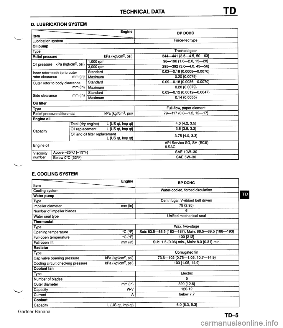
TECHNICAL DATA D. LUBRICATION SYSTEM - Engine ltem BP DOHC - -. Lubrication system Force-fed type E. COOLING SYSTEM Trochoid gear 344-41 I3.5--4.5,s-31 9&l96 {I .&2.0, 15--28) 295-392 {3.0-4.0,43-56) 0.02-0.1 8 {0.000&0.0070) 0.20 {0.0079) 0.09-0.18 (0.0036-0.0070) 0.20 {0.0079) 0.03-0.1 2 {0.0012-0.0047) 0.14 (0.0055) TY pe Relief pressure kPa {kgf/cm2, psi) Oil pressure kPa {kgf/cm2, psi) Inner rotor tooth tip to outer rotor clearance mm {in) Outer rotor to body clearance mm {in) Side clearance mm {in) Water seal type I Unified mechanical seal Thermostat 1,000 rpm 3,000 rpm Standard Maximum Standard Maximum Standard Maximum Oil filter Engine ltem - - Cooling system . . Impeller diameter mm {in) Number of impeller blades Type Relief pressure differential kPa {kgf/cm2, psi) BP DOHC Water-cooled, forced circulation - 75 i2.95) 6 Full-flow, paper element 74-1 17 {0.&1.2, 12-1 7) TY pe . ., . . . - Radiator I Water pump Wax, two-stage v. . . Full-open temperature "c {OF) Full-open lift mm {in) Engine oil TVD~ O~enina tem~erature "C con I Sub: 83.5-86.5 U83-187). Main: 86.5-89.5 (1 88-1 931 100 (21 2) Sub: 1.5 (0.06) min., Main: 8.0 (0.31) min. -. . - . . Cooling circuit checking pressure kPa {kgflcmz, psi) I 103 {I .05, 14.9) I Centrifugal, V-ribbed belt driven TY pe I Coolant fan I 4.0 (4.2, 3.5) 3.6 {3.8,3.2) 3.75 (4.0, 3.3) API Service SG, SH (ECII) ILSAC Capacity Corrugated fin viscosity Above -25°C (-1 3°F) SAE 1 OW-30 number Below 0°C {3Z°F) SAE 5W-30 Total (dry engine) L {US qt, Imp qt) Oil replacement L {US qt, Imp qt) Oil and oil filter replacement L {US qt, Imp qtl Cap valve o~enina pressure kPa {krrf/cm2, psi} 1 73.6--102 {0.75--1.05, 10.7-14.91 Capacity W-V I 120-1 2 Current A 1 below 7.7 Engine oil Type Number of blades Outer diameter mm {in) Coolant Capacity L {US qt, Imp qt) I 6.0 {6.3,5.3) Electric 5 320 (1 2.61 Gartner Banana
Page 1114 of 1708
![MAZDA MX-5 1994 Workshop Manual TD TECHNICAL DATA Idle speed rpm 1 800-900 (850 2 50) [MT], 750-850 (800 f 50) [ATJ lanition timina BTDC I 9"-11 (10 f 1") u F. FUEL AND EMISSION CONTROL SYSTEMS - Engine ltem Item 1 Throat diam MAZDA MX-5 1994 Workshop Manual TD TECHNICAL DATA Idle speed rpm 1 800-900 (850 2 50) [MT], 750-850 (800 f 50) [ATJ lanition timina BTDC I 9"-11 (10 f 1") u F. FUEL AND EMISSION CONTROL SYSTEMS - Engine ltem Item 1 Throat diam](/manual-img/28/57072/w960_57072-1113.png)
TD TECHNICAL DATA Idle speed rpm 1 800-900 (850 2 50) [MT]', 750-850 (800 f 50) [ATJ' lanition timina BTDC I 9"-11' (10' f 1")' u' F. FUEL AND EMISSION CONTROL SYSTEMS - Engine ltem Item 1 Throat diameter mm {in) 1 55 (2.2) 1 Antifreeze solution BP DOHC Specification 1 Throttle body Fuel pump TY pe I Impeller (in-tank) Coolant protection Above -1 6°C (3°F) Above -26°C (-15°F) Above -40°C {-40°n Tv~e -. Output pressure kPa (kgf/cm2, psi) I 294-437 {3.0--6.5,43--92) Fuel filter Specific gravity at 20°C {WF) 1.054 1.066 1.078 Volume percentage % Horizontal draft Water 65 55 45 -. . - Regulating pressure kPa {kgf/cm2, psi) I 280-289 I2.85--2.95, 40.141.9) Fuel iniector Coolant 35 45 55 TY pe IAC valve Solenoid resistance n 1 10.7-1 2.3 (at 20°C (68°F)) Low-pressure side TYP~ Type of drive Resistance n Purge solenoid valve Solenoid resistance n 1 23-27 (at 20°C (68°F)) I Nylon element Pressure regulator TY pe High-ohmic Voltage 13.8 (at 20°C (68"FI) Engine coolant temperature sensor 7 20°C {68"F) I 2.21 -2.69 Resistance kn I 80°C (1 76OF} I 0.287-0.349 High-pressure side Diaphragm i/ Crankshaft position sensor Air valve Openin~l temperature OC {OF) I Below 45 (1 131 Paper element Twe 1 Fuel tank I Hall effect . . . . . . . Capacity L {US gal, Imp gal) I 48 {12.7, 10.5) Air cleaner housing Element type Free play mm (in) I 1-3 {0.039--0.118) I Fuel Oil permeated Specification Accelerator cable Unleaded regular (RON 87 or higher) J +....with system selector (49 B019 9AO) test switch at SELF TEST Gartner Banana
Page 1386 of 1708
I 1400 -1 OIL BUMP 6 FILTER 5EAL,OIL WN ASBESTOS I I SPRI tlG PRESSURE UOUER,OIL YUHP SCKLWIUIL PUMP COVEk GEAR, lCHEW CiEAR,OUTER GASKET. UI L STHAINCR r I HOW ASYESTOS I Gartner Banana
Page 1387 of 1708
1400 -2 * OIL PUMP 8 FILTER ;ASK&'' ,OIL STRAINER 4OSE , WATER-OIL COOL Z IN, :LAMP ,WATER HOSE :ARTRIDOC,OIL FILTE !OXYP ROKI Gartner Banana