1994 MAZDA MX-5 check engine light
[x] Cancel search: check engine lightPage 225 of 1708

ENGINE TUNE-UP - TIMING LIGHT - 45UOFX422 GND Irnr Air Cleaner Element Inspection 1. Check the air cleaner element for excessive dirt and for oil and damage. Caution Cleaning the element with compressed air will re- duce the element's ability to filter the air. Don't use compressed air to clean the element. 2. Replace the element if necessary. ADJUSTMENT Preparation 1. Warm up the engine to normal operating temperature. 2. Turn all electric loads OFF. Headlight switch Blower switch Rear window defroster switch 3. Connect the SST to the data link connector. 4. Connect a timing light to the engine. 5. Connect a tachometer to the data link connector terminal IG- as shown. Ignition Timing 1. Perform Preparation. (Refer to above.) 2. Verify that the idle speed is within the specification; if not, adjust it. Idle speed 4 (Neutral): 800-900 (850 + 50) rpm [MT] (P range): 750-850 (800 & 50) rpm [AT] 3. Set switch A to position 1. 4. Set test switch to SELF TEST. 5. If the SST is not used, connect a jumper wire between the TEN terminal and the GND terminal of the data link connector. 6. Verify that the idle speed is within the specification. ldle speed (Ground the terminal TEN): 650-975 rpm 7. Verify that the timing mark (white) on the crankshaft pulley and the mark on the timing belt cover are aligned. lgnition timing: BTDC 9"-11" (10" & lo) Gartner Banana
Page 244 of 1708

ON-BOARD DIAGNOSIS SYSTEM SWITCH MONITOR FUNCTION Inspection Procedure POWERTRAIN CONTROL MODULE (ENGINE) NEUTRAL SWITCH CLUTCH SWITCH 1 STOPLIGHT SWITCH HEADLIGHT SWITCH REAR WINDOW DEFROSTER SWITCH PARKINEUTRAL SWITCH IDLE SWITCH (IN THROTTLE POSITION SENSOR) BLOWER SWITCH AIR CONDITIONING SENSOR I ' SYSTEM MONITOR LAMP (SELF-DIAGNOSIS 1 Clutch switch (MT) 1 Pedal released I Pedal depressed I In gear I Switch Self-Diagnosis Checker (Monitor lamp) I Liaht ON Liaht OFF . . I I I - I Idle switch (in throttle position sensor) I Pedal depressed I Pedal released 1 Remark ParWneutral switch (AT) I L, S, D and R range I N and P range I I I Stoplight switch (MT) Pedal depressed I Pedal released - I Neutral I Clutch pedal released Neutral switch (MT) - In gear I I Blower switch Headlight switch OFF Blower motor position: "medium" "high" or "super hiah" position I I ON 1. Connect the SST to the data link connector as shown. 2. Turn the ignition switch ON. Check if the monitor lamp il- luminates when each switch is made to function as de- scribed below. If any switch remains activated, the monitor lamp will be illuminated. 3. Connect the SST to the data link connector as shown. 4. Turn the ignition switch to ON (engine off). Check if the monitor lamp illuminates when each switch is adjusted as described above. 45UOFX-173 OFF 1 Air conditioning sensor Rear window defroster switch - ON ON OFF OFF Fan speed control: Low position - Gartner Banana
Page 245 of 1708

F ON-BOARD DIAGNOSIS SYSTEM Procedure - Set conditions to deactivate each switch a All accessories OFF a Transmission in neutral a All pedals released Verify that monitor lamp does not illuminate Neutral and Clutch switches (MT) Parklneutral switch (AT) Depress clutch pedal Verify that monitor lamp does not illuminate Return transmission to neutral NO PC: a Neutral or clutch switch malfunction (Refer to F-146) a Open circuit in related wire harness a Powertrain control module (engine) terminal 1V malfunction (Refer to page F-146) - Shift transmission into gear Verify that monitor lamp illuminates with clutch pedal is re- leased PC: a Clutch switch malfunction (Refer to page F-157) 35UOFX-046 I ParWneutral switch OK Shift into P or N range Check each switch and related wire harness a Clutch and Neutral switch :Refer to page F-I57 a Idle switch (in throttle position sensor) :Refer to page F-154 a Stoplight switch :Refer to Section T Headlight switch :Refer to Section T 1 Check each switch as described I I NO - ldle switch (in throttle position sensor) a Blower switch :Refer to Section T a Air conditioning sensor :Refer to Section U a Rear window defroster switch :Refer to Section T a ParWneutral switch :Refer to Section K YES PC: a ParWneutral switch malfunction (Refer to Section K) a Open or short circuit in related wire harness a PCME terminal 1 V voltage incorrect (Refer to page F-I 46) PCME malfunction - Shift transmission into L, S, D, or P range Check that monitor lamp illuminates 35UOFX-06 NO + YES I 1 I ldle switch OK I L I PC: Throttle position sensor malfunction (Refer to page F-144) a Short circuit in wire harness from throttle position sensor to PCME a PCME terminal 1 N voltage incorrect (Refer to page F-145) a PCME malfunction - Depress accelerator pedal and check that monitor lamp illu- minates f NO --c YES PC: a Throttle position sensor malfunction (Refer to page F-144) Open circuit in wire harness from throttle position sensor to PCME PCME terminal 2M voltage incorrect (Refer to page F-146) Release acceleration pedal and check that monitor lamp does not illuminate 2 YES I I Gartner Banana
Page 294 of 1708

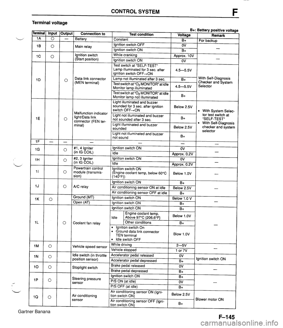
CONTROL SYSTEM F Terminal voltage B+: Battery positive voltage Test condition I Voltage I Remark - - - - - - - - - - - - - - - - - - Connection to Battery Constant Ignition switch OFF Main relay - B+ OV lgnition switch (Start position) For backup - Ignition switch ON While cranking Lamp illuminated for 3 sec. after 1 4.5-5.5V ianition switch OFF+ON 1 B+ Approx. 1 OV Ignition switch ON - - OV Data link connector (MEN terminal) Test switch at "SELF-TEST" .. Lamp not illuminated after 3 sec. Test switch at "02 MONITOR" at idle Monitor lam illuminated & 4.5-5.5v . . I Malfunction indicator IighVData link connector (FEN ter- minal) With Self-Diagnosis Checker and System Selector Test switch at "02 MONITOR" at idle Monitor lamp not illuminated Light illuminated and buzzer sounded for 3 sec. after ignition switch OFF-ON B+ tor tesiswitch at "SELF-TEST" With Self-Diagnosis checker and system selector Below 2.5V 1 Light illuminated and buzzer sounded 1 Below 2.5V I With System Selec- Light not illuminated and buzzer not sounded after 3 sec. I Light not illuminated and buzzer 1 n. 1 B+ not sound I D+ 1 - #I, 4 lgniter (in IG COIL) #2,3 Igniter (in IG COIL) Powertrain control module (transmis- sion) - Ignition switch ON Idle Ignition switch ON Idle lgnition switch ON (Engine coolant temp, below 60°C {I 40°F)) Ignition switch ON AtC relay Air conditioning sensor ON at idle Air conditioning sensor OFF at idle Ground (MT) - OV Approx. 0.2V OV Approx. 0.2V Below 1 .OV B+ Below 2.5V B+ - - - - , * Open (AT) - Ignition switch ON ( Below 1 .O V I Engine coolant temp. I Below .OV I ldle Above 97°C (206.6OF1 Ignition switch ON I I B+ Ignition switch ON Coolant fan relay B+ . - Other conditions lgnition switch On dround data link connector TEN terminal I Blow 1.0" I B+ Vehicle speed sensor ldle switch OFF While driving Vehicle sto~wed ldle switch (in throttle position sensor) 2-5V 1 or 7V . , Accelerator pedal released Accelerator ~edal de~ressed - Stoplight switch OV B+ Brake pedal released Brake ~edal deoressed lgnition switch ON Steering pressure sensor OV B+ I I - Ignition switch ON B+ - PIS ON (at idle) PIS OFF (at idle) Air conditioning sensor Air conditioning sensor ON (Igni- tion switch ON) Air conditioning sensor OFF (Igni- tion switch ON) OV B+ - Below 2.5V B+ Blower motor ON Gartner Banana
Page 314 of 1708

CHARGING SYSTEM G TROUBLESHOOTING Check 1 Check if battery p Check battery (Refer to page G-8) J Check 2 I. Turn ignition switch ON Check wire harness 2. Check if voltage exists at each terminal of alternator Check 3 YES 1. Start engine Check alternator (Refer to page G-10) 2. Check if alternator warning light goes off I YES Check if drive belt t Adjust or replace drive belt (Refer to page G-14) 1 YES I Check for dark current (Refer to page G-3) I Check 1 BATTERY r"; Check 3 I ALTERNATOR WARNING LIGHT Check 2 B+: Battery positive voltage I I I B 1 Approx. 12V 1 Approx. 12V I B+ ON ON (Idle) L S 45UOGX-006 OV Approx. 12V Approx. 1V Approx. 12V B+ B+ Gartner Banana
Page 324 of 1708

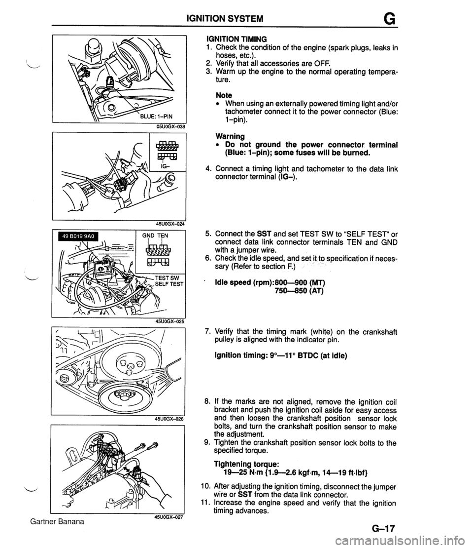
IGNITION SYSTEM G GND TEN I I I IGNITION TIMING 1. Check the condition of the engine (spark plugs, leaks in hoses, etc.). 2. Verify that all accessories are OFF. 3. Warm up the engine to the normal operating tempera- ture. Note When using an externally powered timing light and/or tachometer connect it to the power connector (Blue: l-pin). Warning Do not ground the power connector. terminal (Blue: l-pin); some fuses will be burned. 4. Connect a timing light and tachometer to the data link connector terminal (IG-). 5. Connect the SST and set TEST SW to "SELF TEST" or connect data link connector terminals TEN and GND with a jumper wire. 6. Check the idle speed, and set it to specification if neces- sary (Refer to section F.) ' Idle speed (rpm):800-900 (MT) 75-50 (AT) 7. Verify that the timing mark (white) on the crankshaft pulley is aligned with the indicator pin. Ignition timing: 9"-11" BTDC (at idle) 8. If the marks are not aligned, remove the ignition coil bracket and push the ignition coil aside for easy access and then loosen the crankshaft position sensor lock bolts, and turn the crankshaft position sensor to make the adjustment. 9. Tighten the crankshaft position sensor lock bolts to the specified torque. Tightening torque: 19-25 N-m (1 3-2.6 kgf~m, l4--19 ft.lbf) 10. After adjusting the ignition timing, disconnect the jumper wire or SST from the data link connector. 11. Increase the engine speed and verify that the ignition timing advances. Gartner Banana
Page 325 of 1708

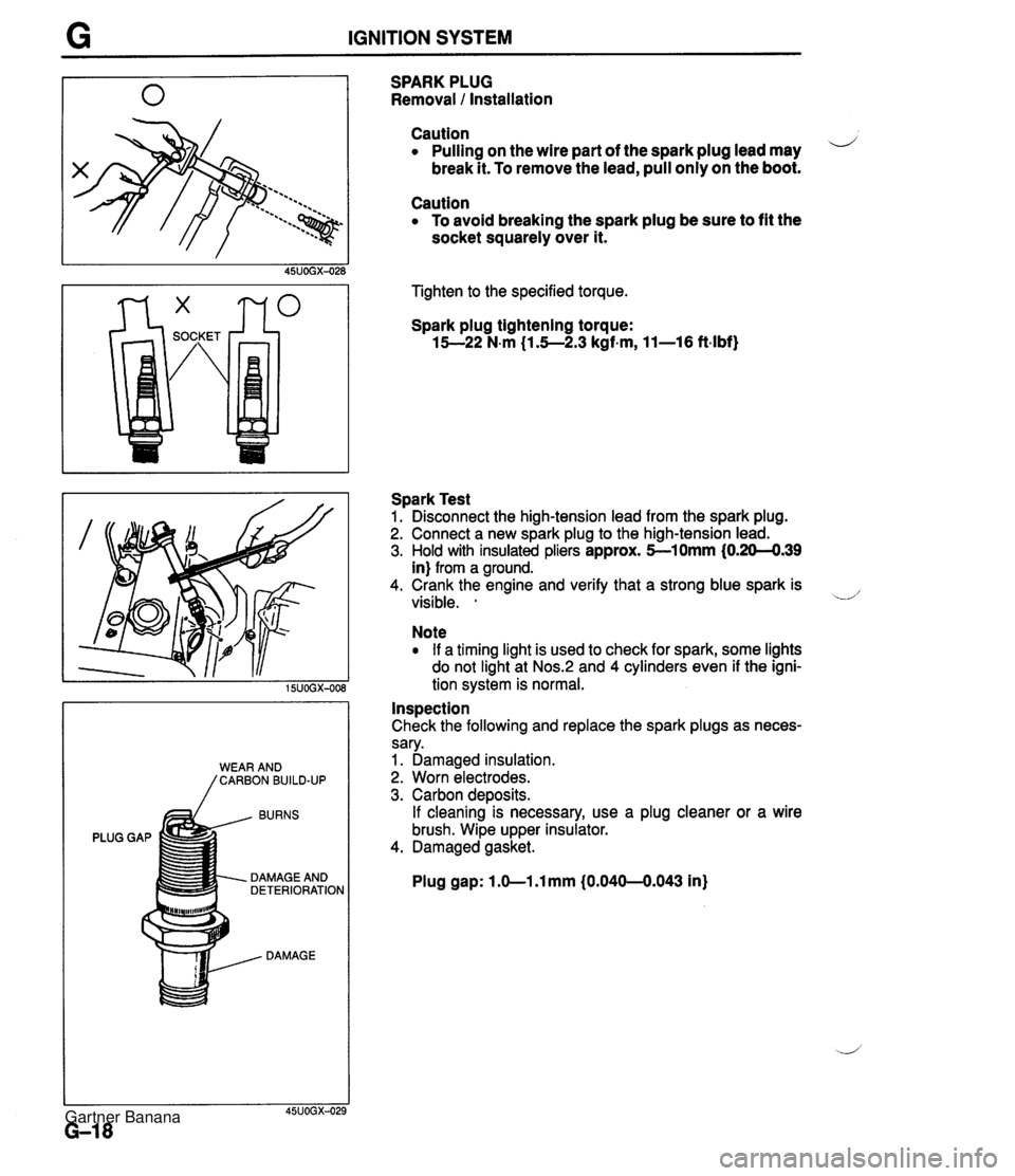
G IGNITION SYSTEM BURNS PLUG GAP DAMAGE AND DETERIORATION DAMAGE SPARK PLUG Removal 1 Installation Caution Pulling on the wire part of the spark plug lead may i/ break it. To remove the lead, pull only on the boot. Caution To avoid breaking the spark plug be sure to fit the socket squarely over it. Tighten to the specified torque. Spark plug tightening torque: 15--22 N-m (1.5--2.3 kgf-m, 11-16 ft-lbf) Spark Test 1. Disconnect the high-tension lead from the spark plug. 2. Connect a new spark plug to the high-tension lead. 3. Hold with insulated pliers approx. 5-10mm (0.20-4.39 in) from a ground. 4. Crank the engine and verify that a strong blue spark is visible. . -.d' Note If a timing light is used to check for spark, some lights do not light at Nos.:! and 4 cylinders even if the igni- tion system is normal. Inspection Check the following and replace the spark plugs as neces- sary. 1. Damaged insulation. 2. Worn electrodes. 3. Carbon deposits. If cleaning is necessary, use a plug cleaner or a wire brush. Wipe upper insulator. 4. Damaged gasket. Plug gap: 1 .O-1 .l mm (0.040-0.043 in) Gartner Banana
Page 409 of 1708

K TROUBLESHOOTING TROUBLESHOOTING GENERAL NOTES A problem with the EC-AT may be caused by the engine, the EC-AT powertrain, the hydraulic control LJ system, or the electronic control system. When troubleshooting, therefore, begin from these points, which can be inspected quickly and easily. The recommended troubleshooting sequence is described below. WHEEL CHOCK 63 TEMPERATURE w-7u'C (1461WF) Step 1 : On-board Diagnosis System Inspection Check for diagnostic trouble code(s) memorized in the powertrain control module (Transmission) with the Self- Diagnosis Checker. (Refer to page K-11 .) Note You can also check the flashing sequence of the hold indicator light for diagnostic trouble code(s). (Refer to page K-1 1 .) Step 2: Mechanical System Test Check the engine stall speed, time lag, and line pres- sure. (Refer to page K-22.) Step 3: Road Test Check the shift point, shift schedule, and shift shock. (Refer to page K-29.) Gartner Banana