Page 316 of 1708

CHARGING SYSTEM G Battery discharge test capable of reading 0.01V Quick charge for 30 min- utes and recheck voltage elo ow 12.4V Above 12.4V I Replace battery el c Apply test load (see test load chart) to the battery using a battery load tester Record battery positive voltage at the end of 15 seconds; is voltage more than specifica- tion? I Measure open circuit voltage of battery 1 Replace battery I I Below 12.4V Abov'e 12.4V Test load I Battew I Load (A1 I Battery posltive voltage with load I Charge battery ( I Battery OK I Terminal and cable 1. Clean and tighten the battery terminals and cables. 2. Coat the terminals with arease. 3. Inspect for corroded or 6ayed battery cables. 4. Check the rubber protector on the positive terminal for proper coverage. Recharging Warning Before performing maintenance or recharging the battery, turn off all accessories and stop the engine. The negative battery cable must be removed first and installed last. Battery S46A24L(S) Caution Do not remove vent caps. Follow carefully the instructions of the battery charger to prevent overcharging. u Do not recharging over 30 minutes to prevent damage the battery. Slow charge (A) Under 3 - -- Quick charge (A) Max. 20 Gartner Banana
Page 317 of 1708

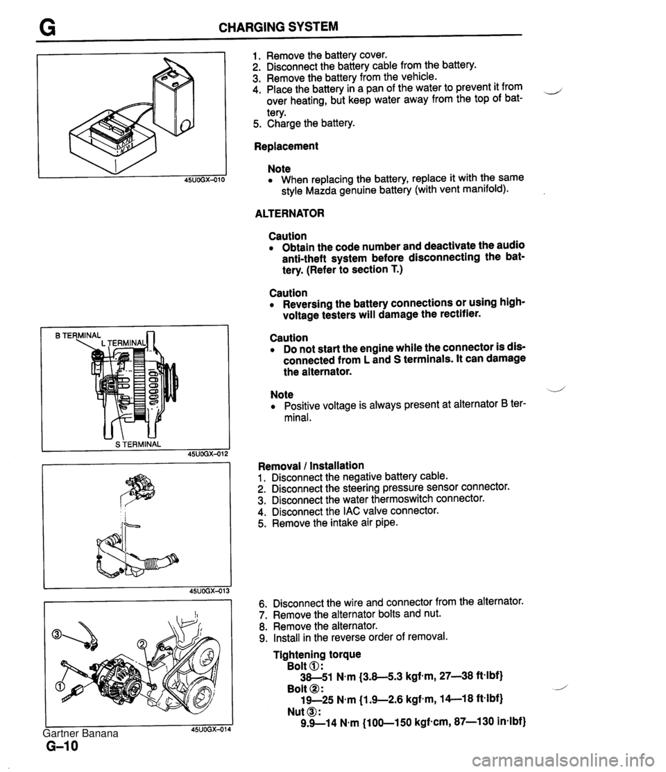
CHARGING SYSTEM B TE S TERMINAL 1. Remove the battery cover. 2. Disconnect the battery cable from the battery. 3. Remove the battery from the vehicle. 4. Place the battery in a pan of the water to prevent it from ,-, over heating, but keep water away from the top of bat- tery. 5. Charge the battery. Replacement Note When replacing the battery, replace it with the same style Mazda genuine battery (with vent manifold). ALTERNATOR Caution Obtain the code number and deactivate the audio anti-theft system before disconnecting the bat- tery. (Refer to section T.) Caution Reversing the battery connections or using high- voltage testers will damage the rectifier. Caution Do not start the engine while the connector is dis- connected from L and S terminals. It can damage the alternator. Note .--,' Positive voltage is always present at alternator B ter- minal. Removal l Installation 1. Disconnect the negative battery cable. 2. Disconnect the steering pressure sensor connector. 3. Disconnect the water thermoswitch connector. 4. Disconnect the IAC valve connector. 5. Remove the intake air pipe. 6. Disconnect the wire and connector from the alternator. 7. Remove the alternator bolts and nut. 8. Remove the alternator. 9. Install in the reverse order of removal. Tightening torque Bolt 0: 38-51 N.m (3.8-5.3 kgf-m, 27-38 ftelbf) Bolt @ : 19-25 N.m j1.9-2.6 kgfem, 14--18 ft-lbf) Nut @I: 9.9--14 N.m (100-150 kgf-cm, 87-1 30 in-lbf) Gartner Banana
Page 329 of 1708
G STARTING SYSTEM Check 1 Check 3 Check 2 STARTER Caution Obtain the code number and deactivate the audio anti-theft system before disconnecting the bat- tery. (Refer to section T.) Removal / Installation 1. Disconnect the negative battery cable. 2. Disconnect the wiring from the starter. 3. Remove the starter bracket. (MT only) 4. Raise the front of the vehicle and support it with safety stands. 5. Remove the bolts and the starter. 6. Install in the reverse order of removal. Tightening torque Nut O: 10-11 N.m (100-120 kgfam, 87-100 in4bf) Bolt, Nut O: 38-51 N.m (3.8-53 kgf-m, 28-38 ft4bf) Bolt 0: 16-22 N.m (1.6-2.3 kgf.m, 12-16 ft-lbf) Bolt 0: 38-51 N.m (3.8-5.3 kgf-m, 28-38 ft-lbf) Gartner Banana
Page 330 of 1708

STARTING SYSTEM I 05-2.0mm {0.020-0.079 in) ( 45UOGX-038 BATTERY B+ Performance Inspection Pull-out test Verify that the pinion is pulled out with battery positive voltage connected to the S terminal and the starter body grounded. Pinion gap check 1. Measure the pinion gap while the pinion is pulled out. Specification: 0.5--2.0mm (0.020-0.079 in) 2. Adjust the pinion gap with an adjustment washer (between drive housing front cover and magnetic switch) if it is not within specification. Return test 1. Disconnect the motor wire from the M terminal. 2. Connect battery positive voltage to the M terminal and ground to the body. 3. Pull out the overrunning clutch with a screwdriver. Verify that it returns to its original position when released. No-load test 1. After adjusting the pinion gap, form a test circuit with a voltmeter and an ammeter. Note Use heavy gauge wires and tighten each terminal fully. 2. Close switch K to run the starter. 3. Check for the following: Starter type 0.95 -- kear shaft soeed rom I Min. 6.600 1 Min. 3.000 1 1.4 Voltage V Current A 4. If not as specified, check for the cause by referring to Inspection. I 11.5 Max. 60 11 Max. 90 Gartner Banana
Page 335 of 1708
STARTING SYSTEM LIMIT 1 I 45UOGX-043 STARTER INTERLOCK SWITCH (MT) Brush If the brushes are worn beyond the wear limit or if the wear is near the limit, replace the brushes. CONTACT PLATES IGNITION SWITCH mm {in} IG1 ROD Standard Wear limit INTERLOCK SWITCH 62-7 - STARTER MT 17 (0.67) 11.5 (0.45) The clutch pedal must be depressed during starting for battery power to be supplied to the starter. AT 17.5 (0.69) 12.0 (0.47) Inspection 1. Disconnect the interlock switch connector. 2. Check continuity of the switch with an ohmmeter. Pedal Depressed Released Continuity Yes No 1 3. If not as specified, replace the interlock switch. Gartner Banana
Page 364 of 1708
J TRANSMISSION REMOVAL 1. Obtain the code number and deactivate the audio antitheft system before disconnecting the battery. (Refer to section T.) 2. is connect the negative battery cable. 3. On level grand, jack up the vehicle and support it evenly on safety stands. 4. Drain the transmission oil into a suitable container. 5. Remove in the order shown in the figure, referring to Removal Note. I. Shift lever knob ?. Rear console 9. Clutch release cylinder 10. Starter I 1 3. Shift lever 11. speedometer cable 4. Undercover 12. Power plant frame (PPF) 5. Performance rod Removal Note ............... page J-1 1 6. Differential mounting pipe 13. Transmission 7. Exhaust pipe J Removal Note ............... page J-12 8. Propeller shaft Service ...................... section L Gartner Banana
Page 414 of 1708

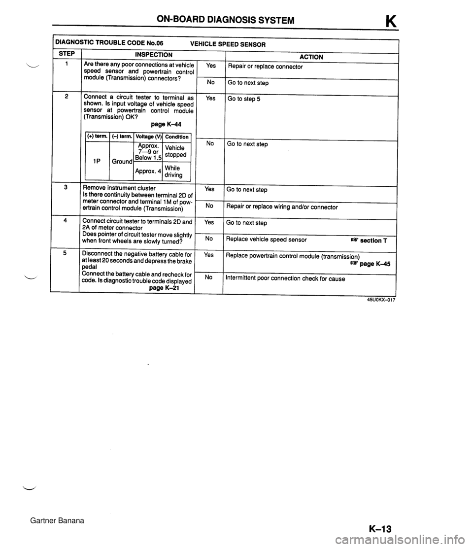
ON-BOARD DIAGNOSIS SYSTEM K )IAGNOSTIC TROUBLE CODE N0.06 VEHICLE SPEED SENSOR INSPECTION STEP ACTION Repair or replace connector Are there any poor connections at vehicle speed sensor and powertrain control module (Transmission) connectors? Yes Go to next step Connect a circuit tester to terminal as shown. Is input voltage of vehicle speed sensor at powertrain control module (Transmission) OK? page K-44 Yes Go to step 5 1 (+) term. I (-) term. ( Voltage (v)( Condition I Go to next step Below 1.5 While Remove instrument cluster Is there continuity between terminal 2D of meter connector and terminal 1 M of pow- ertrain control module (Transmission) Yes Go to next step Repair or replace wiring and/or connector Connect circuit tester to terminals 2D and 2A of meter connector Does pointer of circuit tester move slightly when front wheels are slowly turned? Yes Go to next step Replace vehicle speed sensor section T Disconnect the negative battery cable for at least 20 seconds and depress the brake pedal Connect the battery cable and recheck for code. Is diagnostic trouble code displayed Dane K-21 Yes Replace powertrain control module (transmission) page K-45 Intermittent poor connection check for cause Gartner Banana
Page 415 of 1708

K ON-BOARD DIAGNOSIS SYSTEM - -- )IAGNOSTIC TROUBLE CODE N0.12 THROTTLE POSITION SENSOR ACTION I STEP INSPECTION Are there any poor connections at throttle position sensor and powertrain control module (transmission) connector or termi- nal? Yes Repair or replace connector I Go to next step Go to step 5 Connect a circuit tester to terminal as shown Is input voltage of throttle position sensor (TVO) at powertrain control module (transmission) OK? page K-45 1 (+) term. I (-) term. I Voltage (v)/ Condition 1 Yes No lgnition Go to next step ' 2T Ground valve Approx. closed I 0.8--4.3 position to wide open 1 throttle Go to next step Connect a circuit tester to terminals as shown Is input voltage of throttle position sensor (VREF) at powertrain control module (transmission) OK? page K-44 (+) term. (-) term. Voltage (V) Condition Approx. lgnition 4.55 ;p" 2A Ground Ignition 0 switch OFF Yes Check voltage at terminal 21 of powertrain control module (En- gine) Voltage: 4.5--5.5V (Ignition switch ON) If OK, go to next step If not OK, repair wiring andlor connector Check wiring and connectors form Powertrain control module (transmission) to throttle position sensor If OK, go to next step If not OK, repair wiring andlor connector Is throttle position sensor OK? Section F Yes No Yes Adjust or replace throttle position sensor t@? section F I Replace powertrain control module (transmission) t@? page K-45 is connect the negative battery cable for at least 20 seconds and depress the brake pedal Connect the battery cable and recheck for diagnostic trouble code Is diagnostic trouble code displayed? Daae K-21 Intermittent poor connection Check for cause Gartner Banana