Page 1047 of 1770
Fig. 2 Coolant FlowÐYJ Models with 2.5L EngineÐTypical
7 - 2 COOLING SYSTEMJ
Page 1048 of 1770
Fig. 4 Coolant FlowÐYJ Models with 4.0L
EngineÐTypical
JCOOLING SYSTEM 7 - 3
Page 1061 of 1770
Fig. 17 Draining CoolantÐ4.0L Engine
7 - 16 COOLING SYSTEMJ
Page 1130 of 1770
Fig. 12 Coolant Temperature SensorÐTypical
Fig. 13 Air Temperature Sensor LocationÐ4.0L
Engine
Fig. 14 Air Temperature Sensor LocationÐ2.5L
Engine
JIGNITION SYSTEMS 8D - 5
Page 1147 of 1770
Fig. 8 Coolant Temperature SensorÐTypical
8D - 22 IGNITION SYSTEMSJ
Page 1576 of 1770

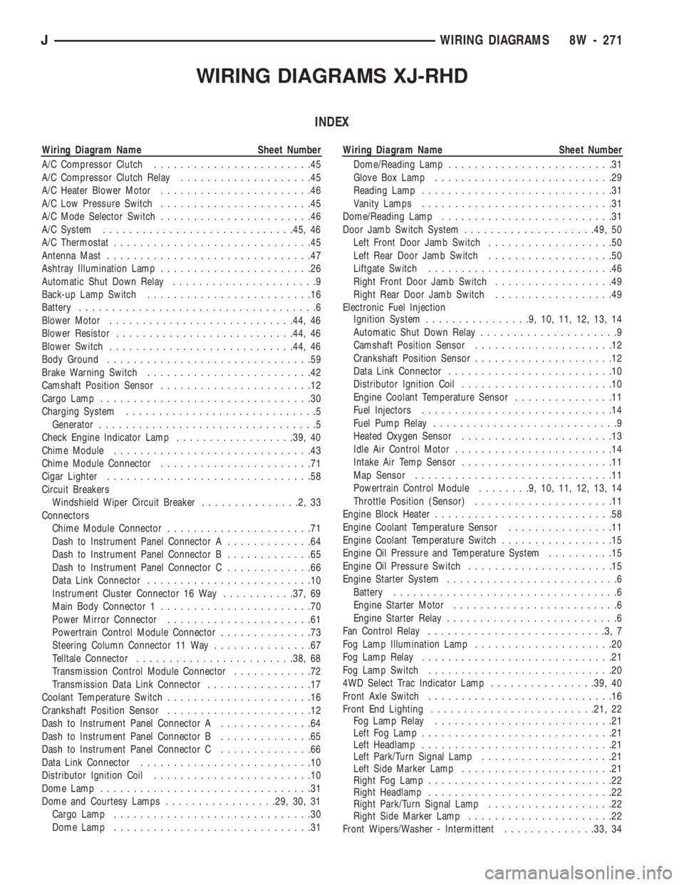
Wiring Diagram Name Sheet Number
A/C Compressor Clutch........................45
A/C Compressor Clutch Relay....................45
A/C Heater Blower Motor.......................46
A/C Low Pressure Switch.......................45
A/C Mode Selector Switch.......................46
A/C System.............................45, 46
A/C Thermostat..............................45
Antenna Mast...............................47
Ashtray Illumination Lamp.......................26
Automatic Shut Down Relay......................9
Back-up Lamp Switch.........................16
Battery....................................6
Blower Motor............................44, 46
Blower Resistor...........................44, 46
Blower Switch............................44, 46
Body Ground...............................59
Brake Warning Switch.........................42
Camshaft Position Sensor.......................12
Cargo Lamp................................30
Charging System.............................5
Generator.................................5
Check Engine Indicator Lamp..................39, 40
Chime Module..............................43
Chime Module Connector.......................71
Cigar Lighter...............................58
Circuit Breakers
Windshield Wiper Circuit Breaker...............2,33
Connectors
Chime Module Connector......................71
Dash to Instrument Panel Connector A.............64
Dash to Instrument Panel Connector B.............65
Dash to Instrument Panel Connector C.............66
Data Link Connector.........................10
Instrument Cluster Connector 16 Way...........37, 69
Main Body Connector 1.......................70
Power Mirror Connector......................61
Powertrain Control Module Connector..............73
Steering Column Connector 11 Way...............67
Telltale Connector........................38, 68
Transmission Control Module Connector............72
Transmission Data Link Connector................17
Coolant Temperature Switch......................16
Crankshaft Position Sensor......................12
Dash to Instrument Panel Connector A..............64
Dash to Instrument Panel Connector B..............65
Dash to Instrument Panel Connector C..............66
Data Link Connector..........................10
Distributor Ignition Coil........................10
Dome Lamp................................31
Dome and Courtesy Lamps.................29, 30, 31
Cargo Lamp..............................30
Dome Lamp..............................31
Page 1667 of 1770
Fig. 15 Upper Radiator Hose, Coolant Recovery
Hose & Fan Shroud
9 - 14 2.5L ENGINEJ
Page 1711 of 1770
Fig. 19 Upper Radiator Hose, Coolant Recovery
Hose, Fan Shroud & Power Steering Pump
9 - 58 4.0L ENGINEJ